Integral Audio Soundstage Series User manual

SKILL LEVEL REQUIRED APPLIES TO
INSTALLATION DIFFICULTY
INSTALLATION TIME
3 OUT OF 5
DO-IT-YOURSELF
4 HOURS
2012-2018 F30 SEDAN W/ HK
2012-2018 F80 M3 W/ HK
BEFORE YOU BEGIN .......................................................................................................................... 2
WHAT’S IN THE BOX - SOUNDSTAGE.................................................................................................. 3
WHAT’S IN THE BOX - SUBWOOFER................................................................................................... 4
TOOLS YOU WILL NEED...................................................................................................................... 5
INSTALLATION:
A. Prep Vehicle ........................................................................................................................ 6
B. Amplifier & Signal Wiring.................................................................................................... 9
C. Soundstage ....................................................................................................................... 13
D. Subwoofer ......................................................................................................................... 20
E. Settings ............................................................................................................................ 25
NOTES & TIPS.................................................................................................................................. 28
TROUBLESHOOTING......................................................................................................................... 28
INSTALLATION GUIDE
SOUNDSTAGE + SUBWOOFER SYSTEM
FOR 2012-2018 BMW 3-SERIES & M3 (F30 & F80) ver. 7/2019

BEFORE YOU BEGIN
2
•Read this Guide completely BEFORE you begin.
•Disconnect the battery negative terminal while working on the vehicle.
IMPORTANT

WHAT’S IN THE BOX
3
SOUNDSTAGE
I. SOUNDSTAGE™ SPEAKER PACKAGE
1. IASS-T 1” Silk Dome Tweeter (Pair)
2. IASS-10M 4” Midrange (Pair)
3. IASS-8SA 8” Shallow Woofer(Pair)
II. SOUNDSTAGE™ CROSSOVER NETWORKS WITH VEHICLE-
SPECIFIC TUNING & EQUALIZATION
4. Midrange-Tweeter Network (Pair) [F3X.MT-XO]
III. INTEGRAL AUDIO 850.5 AMPLIFIER BY ARC AUDIO
IV. INTEGRAL AUDIO SOUNDSTAGE DSP PROCESSOR
V. SIGNAL & SPEAKER WIRING HARNESSES
5. SMARTConnect™ Signal Wiring Harness [F30.WH.SIG]
6. Midrange-Tweeter Connection Harness (Pair)
7. Underseat Woofer Pigtail (Pair)
VI. SOUNDSTAGE HARDWARE
8. Midrange Mounting Adapter & Hardware (Pair)
9. Underseat Woofer Mounting Adapter & Hardware (Pair)
10. Midrange-Tweeter Crossover Mounting Hardware (Pair)
VII. AMPLIFIER INSTALLATION & WIRING
11. Amplfier Power Wiring Harness [F3X.WH.PWR]
12. Gear Rack & Hardware
13. Gear Rack Cover
VIII. INTEGRAL AUDIO PHANTOM™ SUBWOOFER
14. Phantom™ Subwoofer Enclosure [F30.SUB10]
15. Integral Audio Soundstage Series 10” Subwoofer [IA26W4558T03]
IX. SUBWOOFER HARDWARE
16. Subwoofer Mounting Bracket & Hardware
17. Subwoofer Support Bracket & Hardware
18. Neutrik Quick-connect Subwoofer Terminal & Wiring
19. Subwoofer Cover Grille
X. DSP REMOTE CONTROL (OPTIONAL)
20. DSP Remote Level & Preset Control
21. 3M VHB Double-Sided Mounting Tape (3in)
Continued on the next page . . .

TOOLS YOU WILL NEED
4Images Not to Scale
I. TOOLS YOU WILL NEED:
1. Wrenches or Socket Driver & Sockets:
• 8mm
• 10mm deep socket
• Nutdriver or Extension
2. Torx Bits:
• T10
• T20
• T25
• T40
• T50
3. Screwdrivers:
• Regular Slotted &Phillips
4. Plastic Panel Removal Tool(s)
5. 1/8” Allen (Hex) Wrench
6. Drill & 1/2” drill bit [DSP REMOTE ONLY]
7. Electrician’s Wire Fish [DSP REMOTE ONLY
8. Magnetic Parts Tray [Optional]
6
8
5
4
2
7
1
9

A.
PREP VEHICLE
5
1. REMOVE BATTERY COVER
Remove battery cover by turning the locking knob and lifting out
the cover.
2. DISCONNECT BATTERY NEGATIVE TERMINAL
Disconnect battery negative terminal with 10mm deep socket.
3. REMOVE TRUNK FLOOR PANEL
Remove the trunk oor panel.
4. REMOVE TRUNK CENTER BIN (STEP 1)
Locate the center pin of the expansion clip at the forward passen-
ger side corner of the liner.
5. REMOVE TRUNK CENTER BIN (STEP 2)
With a plastic panel removal tool, pry out center pin of the expan-
sion clip. Pry out clip base. Remove bin liner.

A.
PREP VEHICLE
6
6. REMOVE TRUNK REAR SILL
Remove the trunk rear sill by removing the (4) center pin expan-
sion clips along the inner side. Lift the lower front edge of the sill
forward to clear the D-rings, then give a rm lift up to release the
friction clips holding the upper portion.
7. FOLD DOWN DRIVER SIDE REAR SEAT
Pull the rear seat release located in the trunk, fold down the driv-
er-side rear seat.
8. REMOVE DRIVER-SIDE REAR QUARTER PANEL TRIM (STEP 1)
Locate the luggage D-ring tie down at the forward driver-side of
the trunk. Pry off the black plastic cover. Remove the Torx T-40
screw. Lift out the D-ring assembly.
9. REMOVE DRIVER-SIDE REAR QUARTER PANEL TRIM (STEP 2)
There are (3) center-pin expansion clips that fasten the rear quar-
ter panel trim to the car - locate & remove the one in the upper
part of the rear cubby area.
10. REMOVE DRIVER-SIDE REAR QUARTER PANEL TRIM (STEP 3)
Then locate & remove the one on the side, under the parcel shelf
area. This one is attached to a plastic bracket. Remove the ex-
pansion clip on the upper portion of the bracket, and leave the
bracket attached to the quarter-panel trim.

A.
PREP VEHICLE
7
11. REMOVE DRIVER-SIDE REAR QUARTER PANEL TRIM (STEP 4)
Then locate & remove the one on the forward edge of the panel,
by the rear seat back.
12. REMOVE DRIVER-SIDE REAR QUARTER PANEL TRIM (STEP 5)
Now remove the trim panel. Start at the forward edge. Lift clear/
free the forward edge from behind the trim at the sides of the
rear seat backs and pull the panel out 4-6 inches.
DO NOT COMPLETELY REMOVE YET.
13. REMOVE DRIVER-SIDE REAR QUARTER PANEL TRIM (STEP 6)
Free panel edge along area (1). Then carefully open the split in
the panel at area (2) by pulling the split directly apart (i.e. not
sideways) and free the panel from around the trunk support arm.
DO NOT COMPLETELY REMOVE YET.
14. REMOVE DRIVER-SIDE REAR QUARTER PANEL TRIM (STEP 7)
Disconnect the plug on the back of the 12V power outlet, then
remove the panel from the vehicle.
15. REMOVE PLASTIC COVER
Remove the nut fastening the plastic cover over the amp with a
10mm socket. Remove the cover.

B.
AMPLIFIER & SIGNAL WIRING
8
16. REMOVE THE FACTORY AMPLIFIER & BRACKET
Using a 10mm socket, remove the nut fastening the factory am-
plier bracket to the vehicle. Slide the amplier bracket forward
to clear the mushroom studs and remove the amp and bracket.
This step is optional, but makes accessing the connectors easier
and is recommended.
17. DISCONNECT FACTORY AMPLIFIER POWER CONNECTOR
Press down on the locking tab and remove the amp power con-
nector (1).
18. DISCONNECT FACTORY AMP 20-PIN SIGNAL CONNECTOR
Slide the locking outer housing to release and remove the 20-pin
signal connector.
19. CONNECT THE SIGNAL WIRING HARNESS
Connect the 20-pin “T” portion of the signal wiring harness
between the amplier and the 20-pin factory signal connector
removed in the last step.
20. LOCATE THE ASD MODULE AND UNPLUG
The ASD module is located behind the HK amplier. Press down
on the locking tab, open the locking lever, and unplug the harness
from the module.

9
21. SWAP ASD WIRING HARNESS HOUSING (PART 1)
Remove the inner connectors from the gray housing by prying
open the latch where indicated (each side) and sliding the inner
connectors out.
22. SWAP ASD WIRING HARNESS HOUSING (PART 2)
Insert the gray and black inner connectors from the last step into
the black outer housing included in the Soundstage kit. The inner
connectors are keyed and will only insert one way into the outer
housing.
23. PLUG ASD WIRING INTO SIGNAL HARNESS
Connect the ASD wiring with the new black housing to the black
housing (1) shown.
24. ROUTE SIGNAL WIRING INTO CENTER TRUNK COMPARTMENT
Route the Signal Wiring Harness along the bottom of the factory
amplier compartment to the rear of the compartment, then up
over the beam running lengthwise, then to the center trunk com-
partment. Shown with panels reinstalled for clarity as to nished
routing. The dotted red line is the harness behind the panels.
25. HARDWARE SELECTION
Locate the Power Wiring Harness [F3X.WH.PWR].
REMOVE THE FUSE FROM THE FUSE HOLDER, IF INSTALLED.
[Old version of harness shown]
B.
AMPLIFIER & SIGNAL WIRING

10
26. ATTACH POSITIVE TERMINAL TO BATTERY
Locate the terminal attachment point shown. Remove the nut
with a 10mm socket and attach the positive wire terminal to the
battery terminal.
27. ATTACH NEGATIVE TERMINAL TO VEHICLE GROUND
Locate the vehicle ground point shown. Attach the negative ter-
minal.
28. ROUTE POWER WIRING INTO CENTER TRUNK COMPARTMENT
Route power wiring harness into the center trunk compartment.
29. HARDWARE SELECTION
Locate the (4) Amp Rack Mounting Points and Flange Nuts
30. ATTACH AMP RACK MOUNTING HARDWARE
Attach the (4) mounting feet to the amp rack with the ange nuts.
Do not remove the liner from the adhesive yet.
B.
AMPLIFIER & SIGNAL WIRING

11
31. PLACE GEAR RACK INTO TRUNK CENTER COMPARTMENT
Place the gear rack into the trunk center compartment
32. REMOVE AMPLIFIER COVER
Remove the (4) hex screws and lift the cover off the amplier.
33. PLACE DSP AND AMPLIFIER ON GEAR RACK
Place the DSP and the Amplier on the gear rack. Do not fasten
them yet
34. DSP CONNECTIONS
Connect the 4-pin DSP power connector (1) and 24-pin DSP input/
output connector (2).
35. AMPLIFIER CONNECTIONS
(1) Connect the power wiring and remote turn-on wires (carefully
note + and - for power - red = positive).
(2) Connect the input RCAs according to the labels (1 & 2 wires to
input 1 & 2, etc).
(3) Connect the output connectors according to labels.
B.
AMPLIFIER & SIGNAL WIRING

C.
SOUNDSTAGE
12
36. ATTACH DSP AND AMPLFIER TO GEAR RACK
Line the DSP and amplier up over the correct holes in the gear
rack. Using the (8) #6 x 1/4” screws, attach the DSP and the ampli-
er to the gear rack
Replace the amplier cover.
37. GEAR RACK COVER PANEL
Place the gear rack cover panel on top of the gear rack. To re-
move, simply press down on the left side to raise the right edge
up.
38. REMOVE UNDER-SEAT WOOFER (STEP 1)
Slide the passenger-side front seat all the way back Use a Torx
T-50 to remove the two bolts holding the front of the seat brack-
ets.
39. REMOVE UNDER-SEAT WOOFER (STEP 2)
Now slide the seat all the way forward. Remove the two bolts
holding the rear of the seat.
40. REMOVE UNDER-SEAT WOOFER (STEP 3)
Release the seat-back to the full forward position. You can now
lean the seat all the way back and it will stay in that position, giv-
ing you access to the underseat area. You may have to move the
seat a little forward or backward to get it to stay. You do not need
to disconnect the airbag connecter (we advise against it), but just
be aware that it is there and take care with it.

C.
SOUNDSTAGE
13
41. REMOVE UNDER-SEAT WOOFER (STEP 4)
Remove the four Torx T-20 screws holding the USW cover and
remove the cover.
42. REMOVE UNDER-SEAT WOOFER (STEP 5)
Remove the Door Sill cover trim (1) by rmly pulling up to release
the four clips located underneath (2).
43. REMOVE UNDER-SEAT WOOFER (STEP 6)
Some or all of the plastic clips (1) may still be stuck to the vehicle,
remove them and put them back on the Door Sill cover trim. A
panel removal pry tool (2) works well.
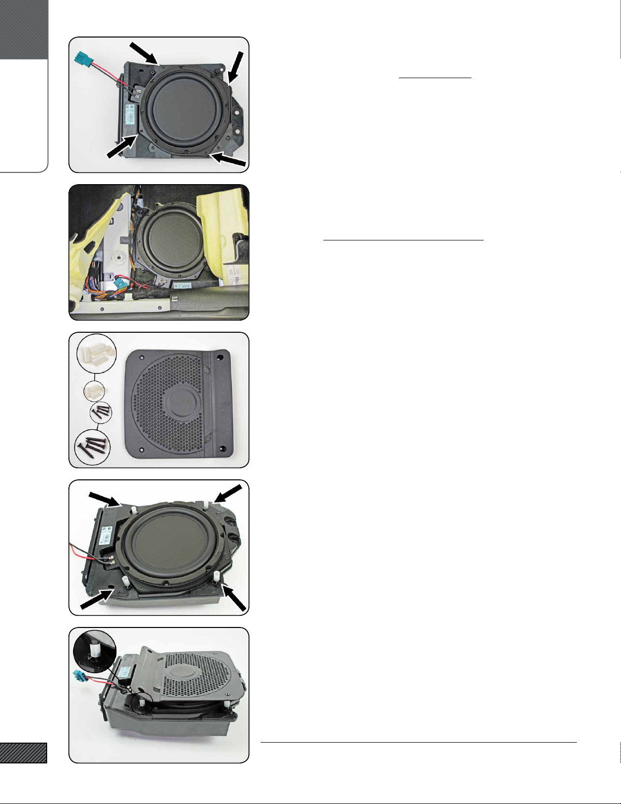
44. REMOVE UNDER-SEAT WOOFER (STEP 7)
Pull up the carpet to access the USW enclosure. Use a 10mm
socket to remove the two nuts (1). Detach the wire bundle clip
attached to the top corner of the USW enclosure (2).
Remove the enclosure by lifting up the inner edge rst, then lift-
ing up and towards the middle of the vehicle. Unplug the wiring/
connector by depressing the locking tab in the connector. Remove
the USW enclosure from the vehicle.
45. REMOVE UNDER-SEAT WOOFER (STEP 8)
Place the USW enclosure on a workbench or other solid work sur-
face. Remove the four Torx T-10 screws (1). Starting at the stron-
gest point (2) carefully pry the woofer from the enclosure.
REPEAT THE PREVIOUS 8 STEPS FOR THE DRIVER SIDE
C.
SOUNDSTAGE
14
46. INSTALL THE IASS-8S WOOFERS IN THE USW ENCLOSURE
Use the four #6 x 1.25” Pan Head Screws to mount the woofer to
the enclosure (these are the longer, thinner screws with a round-
ed head - don’t confuse them with the cover screws which are a
little thicker and shorter and have a at head).
47. RE-INSTALL THE USW ENCLOSURE
Re-install the enclosure in the vehicle. It may take a little wig-
gling to get the open end (the side towards the door sill) to slide
into its slot. Make sure all wiring is run clear. Replace the two
nuts removed previously and tighten with a 10mm socket.
Connect the USW plug to the factory connector. Replace the car-
pet.
48. HARDWARE SELECTION
Select the remaining items from the Underseat Woofer Hardware
Kit: the eight Nylon Spacers and the eight #8 x 1” Flat Head Screws.
49. INSTALL THE USW COVER GRILLE (STEP 1)
Place the spacers over the screw bosses as shown.
(enclosure shown removed for clarity)
50. INSTALL THE USW COVER GRILLE (STEP 2)
The raised “feet” on the cover grille t over the spacers and
should lock into place. Attach the cover with the four #8 x 1” at
head screws. Put the seat back in place, but do not re-bolt it yet!
(enlclosure shown removed for clarity)
REPEAT THE PREVIOUS 8 STEPS FOR THE OTHER SIDE

C.
SOUNDSTAGAE
15
51. REMOVE THE DRIVERS SIDE DOOR TRIM (STEP 3)
Remove the door handle trim cover (1). Look for the small open-
ing indicated by the arrow and start there. Work your way
around the edge and remove the trim.
52. REMOVE THE DRIVERS SIDE DOOR TRIM (STEP 4)
Remove the two Torx T-25 screws shown at the arrows. You will
likely need a nut driver or socket extension to reach them.
53. REMOVE THE DRIVERS SIDE DOOR TRIM (STEP 5)
Remove the Door Trim Panel. Start where the arrow is pointing.
Insert your plastic panel removal tool between the door trim and
the door sheet metal. Pry up until the clips release and you can
get your ngers behind the panel. Pull rmly. Work your way
around the bottom of the door rst., then up to the top. Be care-
ful of the door lock indicator - lift the trim panel up and over the
lock indicator.
54. REMOVE THE DRIVERS SIDE DOOR TRIM (STEP 6)
You do not need to remove the door panel trim completely, but
you can if you want. You can leave it attached and prop up the
bottom, or you can disconnect the door handle release and the
remaining wiring and remove the panel completely.
55. REMOVE THE FACTORY MIDRANGE DRIVER
Remove the three Torx T-20 screws indicated. Unplug and remove
the midrange driver.
Retain the Torx T-20 screws, you will use them to mount the new
midrange.

C.
SOUNDSTAGE
16
56. LOOSEN UPPER DOOR TRIM
Loosen the “mirror sail” portion of the upper door trim. Pull out
on the trim at the bottom of the mirror sail to release the forward
edge, then out and around to release the rear edge (by the win-
dow). You do not need to remove the trim completely, just loosen
it enough to gain access to the tweeter behind.
57. REMOVE FACTORY TWEETER
Remove the foam insert. Remove the factory tweeter by releasing
the three plastic catches indicated by the arrows.
58. TWEETER LOGO BADGES (STEP 1)
Remove the tweeter grille by prying up the tabs and lifting the
grill out.
59. TWEETER LOGO BADGES (STEP 2)
Remove the hk badges by prying up the locking metal tabs. Afx
the Integral Audio tweeter badges and replace the tweeter grille.
60. INSTALL IASS-T1C TWEETER
Install the IASS-T1C tweeter into the housing, it will snap right in.

C.
SOUNDSTAGE
17
61. ROUTE TWEETER PIGTAIL AND REPLACE TRIM PANEL
Replace the foam insert and route the tweeter pigtail wiring thru
the foam channel.
Replace/re-install the trim panel.
62. INSTALL MIDRANGE DRIVER AND ROUTE MIDRANGE PIGTAIL
Peel back the corner of the foam door liner and route the mid-
range pigtail wiring thru this opening. Install the midrange driv-
er using the factory torx screws removed earlier.
Carefully pull out any slack in the midrange pigtail wiring.
63. CONNECT MIDRANGE/TWEETER WIRING HARNESS
Connect the three branches of the midrange/tweeter wiring har-
ness.
Run the wiring clear of the midrange driver and clear of door pan-
el mounting points. It can be helpful to tuck the tweeter wiring
into the adhesive of the foam door liner.
64. MOUNT MIDRANGE/TWEETER CROSSOVER (STEP 1)
Route the midrange/tweeter harness to the lower rear of the door
panel. Connect to the midrange/tweeter crossover and do a test
t of the crossover (1). The crossover should t completely within
the door panel on as at a section as possible.
65. MOUNT MIDRANGE/TWEETER CROSSOVER (STEP 2)
Remove the backing from the VHB adhesive tape and rmly press
the crossover and mounting plate onto the door panel for approx-
imately 30 seconds, ensuring a good bond. The adhesive is very
aggressive and will continue to increase strength over a 48 hour
period.

C.
SOUNDSTAGE
18
66. REPLACE DOOR PANEL
Insert door lock indicator (1) thru hole. Then align the ve clips
along the top of the panel (2). Wiggle the panel slightly to be sure
all clips are aligned. Give a rm strike over each clip to lock in
place. Repeat for the remaining door clips. TIP: a bit of masking
tape on the panel in the location of the clips can help locate them.
Do not nish re-installing the panel until after testing!
REPEAT PREVIOUS STEPS FOR THE PASSENGER SIDE
67. SUBWOOFER INSTALLATION
Locate the IASW264558T03 Subwoofer, Subwoofer Enclosure, Sub-
woofer Hardware Kit, and Speaker Grille.
68. MOUNT THE SUBWOOFER IN THE ENCLOSURE
Connect the Subwoofer Internal Wiring Harness [F30.WH.SUB-INT]
to the Neutrik terminal in the enclosure. Note polarity markings
on the Neutrik terminal! Connect the other end to the subwoofer.
Mount the subwoofer to the enclosure using the eight #10-24 x
1” Button Head Cap Screws and tighten with a 1/8” Allen wrench.
Insstall the speaker grille.
69. SUBWOOFER SUPPORT BRACKET
Install the Subwoofer Support Bracket [F30.SUB.HNG.BRKT] (2).
The upper end mounts on the course-threaded shown at (3). The
bracket has three holes for t adjustment, start with the center
hole. Fasten with the Flange Nut from the Hardware Kit.
The lower end of the Subwoofer Support Bracket will be secured
underneath the hole shown at (4) in the next step.
NOTE: different version of Soundstage amp shown
70. SUBWOOFER MOUNTING BRACKET
Slide the two Clip On Nuts (1) over the holes in the uprights in the
Subwoofer Mounting Bracket. Slide the clips on over the outer edge.
The holes in the clips should align with the holes in the bracket.
Use the 1/4” Serrated Flange Bolts and Nuts to fasten the bracket
through the holes (2). Be sure to fasten the Subwoofer Support
Bracket underneath the hole on the right.
The lower mounting bracket holes are slotted to allow for side-to-
side adjustment if needed. Start with them centered.

D.
SUBWOOFER
19
71. REMOVE 12V PLUG & PLASTIC COVER PANEL
Remove the 12V plug from the trunk trim panel removed earlier.
Slide/press to one side to release the locking tabs and remove.
Remove the plastic cover panel (2).
72. REMOVE NETTING & BRACKET
Remove the cubby cargo netting & bracket. Use a small screw-
driver to pry open the teeth on the locking push-nuts (1) on both
sides. Remove the bracket. Remove the plastic base clips (2) by
unscrewing the top from the base.
73. REMOVE PLASTIC COVER PANEL
Remove the plastic cover panel (2) by freeing the plastic locking
tabs underneath.
74. SUBWOOFER WIRING (NEUTRIK PLUG)
Place the rear quarter panel trim back in the vehicle. Insert the
subwoofer wiring through the opening where the 12V plug was
removed.
75. REPLACE TRUNK TRIM PANEL
Replace the rear quarter panel trim. Start by insterting the for-
ward edge behind the trim at the side of the rear seat backs (1).
Carefully open the slit in the panel (2) and place around the trunk
lid support. Replace the rubber seal (3) over the edge of the panel.

D.
SUBWOOFER
20
76. CONNECT SUBWOOFER
Connect the Neutrik plug to the subwoofer. Slide the subwoofer
into the compartment. Do not attach the mounting screws yet.
77. FASTEN SUBWOOFER
Once you’ve completed settings and conrmed everything is oper-
ating correctly, fasten the subwoofer. The CAD image at left has
some transparancy so you can see how the bolts attach (1). Use
the two #10-24 x 2.5” Socket Head Cap Bolts and Black Flat Washers.
Make sure the enclosure is fully seated into the compartment.
Press the bolts through the carpet and into the hole until they
make contact with the bracket. Start the threads by hand!
You only need to snug the bolts down, DO NOT OVERTIGHTEN!
78. SUBWOOFER LOGO BADGE
Afx the Rectangular Domed Logo Badge to the subwoofer grille (3)
as shown.
79. SETTINGS
In the vehicle audio settings, center fade and balance, zero out all
bass/treble and equalization, and turn off Logic 7.
80. SET BASS & TREBLE TO FLAT
From the music control section in the headunit, select TONE ->
BASS. Set the bass level to at (centered dial). Repeat for TREBLE.
These are cricial! Center the BALANCE and FADER
Select TONE -> VOLUME SETTINGS -> GONG. Set the gong vol-
ume to the lowest level. You can adjust this back up to preference
later.
SETTINGS
This manual suits for next models
11
Other Integral Audio Car Stereo System manuals


Popular Car Stereo System manuals by other brands

Sony
Sony CDX-C90 - Fm/am Compact Disc Player Installation and connections

JVC
JVC KD-DV4206 Installation & connection manual

Rockford Fosgate
Rockford Fosgate RFX9020M Installation & operating guide

Philips
Philips CEM2100/00 quick start guide

Alpine
Alpine Jaguar 6W83-18C808-AB Service manual

Teac
Teac TE-900 installation manual

Kenwood
Kenwood KDC-MP628 Service manual

Becker
Becker Traffic Pro 7945 installation guide

JVC
JVC KD-DV7404 Installation and connection manual

JEHNERT SOUND DESIGN
JEHNERT SOUND DESIGN 75075 installation instructions

Blaupunkt
Blaupunkt Colorado DJ50 operating instructions

Sony
Sony XR-C8100R Installation/connections


