Integral Audio SoundstageDSP User manual

SKILL LEVEL REQUIRED APPLIES TO
INSTALLATION DIFFICULTY
INSTALLATION TIME
3 OUT OF 5
DO-IT-YOURSELF
3-4 HOURS
2014+ F22 COUPE [HIFI & HK]
2015+ F23 CONVERTIBLE [HIFI &
HK]
2016+ M2 [HIFI & HK]
BEFORE YOU BEGIN .......................................................................................................................... 2
WHAT’S IN THE BOX........................................................................................................................... 3
TOOLS YOU WILL NEED...................................................................................................................... 5
INSTALLATION: .................................................................................................................................. 6
NOTES & TIPS.................................................................................................................................. 28
TROUBLESHOOTING......................................................................................................................... 28
INSTALLATION GUIDE
SoundstageDSPTM for BMW 2-Series
FOR 2014+ BMW 2-SERIES & M2 [ver. 11/20]

BEFORE YOU BEGIN
2
•Read this Guide completely BEFORE you begin.
•Disconnect the battery negative terminal while working on the vehicle.
•This guide covers several different vehicle models and options. Some
steps only apply to certain installations or vehicles. Step images are
labeled with a black bar across the top:
-[HARMAN/KARDON ONLY] step applies only if your vehicle is factory-equipped with the
harman/kardon audio system
-[HIFI ONLY] step applies only if your vehicle is factory-equipped with the HIFI audio sys-
tem (OPTION CODE $676)
-[ASD ONLY] step applies only if you the vehicle is equiped with Active Sound Design.
-If there is no label, the step applies to ALL installations
-Because each kit may apply to more than one vehicle, your kit may include extra items.
IMPORTANT

WHAT’S IN THE BOX
3
SOUNDSTAGE
I. SOUNDSTAGE™ SPEAKER PACKAGE
1. IASS-T 1” Silk Dome Tweeter (Pair)
2. IASS-100M 4” Midrange (Pair)
3. IASS-8SA 8” Shallow Woofer(Pair)
II. SOUNDSTAGE™ CROSSOVER NETWORKS WITH VEHICLE-
SPECIFIC TUNING & EQUALIZATION
4. Midrange-Tweeter Network (Pair) [F87.MT-XO]
III. INTEGRAL AUDIO AMPLIFIER (BY ARC AUDIO)
5. PS8-50 DSP Amplifier by ARC Audio
6. BMW OEM-style Mounting Bracket
IV. SIGNAL & SPEAKER & POWER WIRING HARNESSES
7. SMARTConnect™ Signal Wiring Harness [F87.WH.SIG]
8. Midrange-Tweeter Connection Harness (Pair)
9. Underseat Woofer Pigtail (Pair)
10. Amplfier Power Wiring Harness [F87.WH.PWR]
11. ASD-Defeat Harness
V. SOUNDSTAGE HARDWARE
12. Midrange Mounting Adapter & Hardware (Pair)
13. Underseat Woofer Mounting Adapter & Hardware (Pair)
14. Midrange-Tweeter Crossover Mounting Foam (Pair)
Continued on the next page . . .

TOOLS YOU WILL NEED
4Images Not to Scale
I. TOOLS YOU WILL NEED:
1. Wrenches or Socket Driver & Sockets:
• 8mm
• 10mm deep socket
• Nutdriver or Extension
2. Torx Bits:
• T10
• T20
• T25
• T40
• T50
3. Screwdrivers:
• Regular Slotted &Phillips
4. Plastic Panel Removal Tool(s) [INCLUDED]
5. Magnetic Parts Tray [Optional]
6. Multimeter [Testing/Troubleshooting only]

A.
INSTALLATION
5
1. REMOVE TRUNK FLOOR PANEL
Remove the trunk oor panel.
2. DISCONNECT BATTERY NEGATIVE TERMINAL
Disconnect battery negative terminal (1) with 10mm deep socket.
3. REMOVE TRUNK REAR SILL
Remove the trunk rear sill by removing the (4) center pin expan-
sion clips along the inner side. Release the clips by prying out the
center pin with a panel removal tool or screwdriver, then remove
the outer portion of the clip.
Lift the lower front edge of the sill forward to clear the D-rings,
then give a rm lift up to release the friction clips holding the
upper portion.
4. FOLD DOWN DRIVER SIDE REAR SEAT
Pull the rear seat release located in the trunk, fold down the driv-
er-side rear seat.
5. REMOVE DRIVER-SIDE REAR QUARTER PANEL TRIM (STEP 1)
Locate the luggage D-ring tie down at the forward driver-side of
the trunk. Pry off the black plastic cover. Remove the Torx T-40
screw. Lift out the D-ring assembly.

A.
INSTALLATION
6
6. REMOVE DRIVER-SIDE REAR QUARTER PANEL TRIM (STEP 2)
Remove the three center-pin expansion clips (1) that fasten the
rear quarter panel trim to the car. Remove the trim panel - start
at the rear and pull up and out. Carefully unplug the 12V recepta-
cle (2) before removing.
7. REMOVE THE FACTORY AMPLIFIER & BRACKET
Remove the bracket containing the factory amplier and ASD
module. Using a 10mm socket, remove the nut (1) fastening the
bracket to the vehicle. Slide the bracket forward to clear the
mushroom studs and remove the amp and bracket.
8. DISCONNECT FACTORY AMPLIFIER HARNESS
Disconnect the factory wiring harness from the amplier by
pressing in the locking tab (1) and sliding the locking lever (2) to
the left as viewed in the image.
9. DISCONNECT THE ASD MODULE WIRING
The ASD module is located behind the factory amplier. Press
down on the locking tab, open the locking lever, and unplug the
harness from the module.
10. REMOVE THE FACTORY AMPLIFIER FROM THE BRACKET
Using an 8mm socket, remove the bolt that fastens the factory
amplier to the bracket. Slide the amplier off the bracket (you
may need to gently use a screwdriver to free the amp from the
bracket).

A.
INSTALLATION
7
11. MOUNT NEW AMP TO ADAPTER PLATE & BRACKET
Mount the ARC Audio PS8-50 amp to the adapter plate using the 4
4mm machine screws and acorn nuts. Insert the screws from the
bottom of the plate, attach the acorn nuts on the top.
Slide the amplier and plate on the factory bracket and fasten
with the original machine screw (1). Orient the amplifer so that
the wiring connections are towards the OUTSIDE of the vehicle.
12. SWAP ASD WIRING HARNESS HOUSING (PART 1)
Due to the keying of the connectors (the series of notches and
ridges), the OUTER clamshell housings of the connectors on
the factory ASD harness and the ASD-Defeat harness must be
swapped.
Remove the inner connectors from the gray factory ASD housing
by prying open the latch where indicated (each side) and sliding
the inner connectors out.
13. SWAP ASD WIRING HARNESS HOUSING (PART 2)
Insert the gray and black inner connectors from the last step into
the black outer housing on the ASD Defeat Harness. The inner
connectors are keyed and will only insert one way into the outer
housing.
14. CONNECT THE ASD-DEFEAT HARNESS
This is what the nal assembly should look like - the original gray
clamshell housing on the ASD factory harness should now be on
the end of the ASD Defeat Harness. Connect the ASD-Bypass Har-
ness to the ASD Module, and the factory ASD harness to the other
end of the ASD Defeat Harness.
[NOTE: ASD Module shown disconnected for clarity]
15. CONNECT SIGNAL WIRING HARNESS
Connect the 3 branches of the Signal Harness to the ARC PS8-50
as shown.

A.
INSTALLATION
8
16. ATTACH POSITIVE TERMINAL TO BATTERY
Locate the terminal attachment point shown. If the terminal is
covered with a red plastic cap, remove it. Remove the nut with
a 10mm socket and attach the positive wire ring terminal of the
Power Wiring Harness to the battery terminal.
17. ATTACH NEGATIVE TERMINAL TO VEHICLE GROUND
Locate the vehicle ground point shown. Loosen and remove the
nut with a 13mm socket. Place the negative terminal on top of
the battery ground terminal and re-fasten
18. CONNECT POWER WIRING HARNESS
REMOVE THE FUSE FROM THE FUSE HOLDER, IF INSTALLED.
Connect the positive and negative to the amplier. BE SURE TO
OBSERVE THE CORRECT POLARITY!
19. ROUTE POWER WIRING INTO CENTER TRUNK COMPARTMENT
Route power wiring harness along the edge of where the trunk
oor panel sits and into the amplier compartment
20.RE-MOUNT AMPLIFIER BRACKET & CONNECT SIGNAL HARNESS
Mount the amplier bracket back in it’s original position. Connect
the Signal Wiring Harness to the factory wiring harness (1).
Proceed to the next section. Do not re-install the trim/interior
panels until after you’ve conrmed operation.

9
21. REMOVE UNDER-SEAT WOOFER (STEP 1)
Slide the passenger-side front seat all the way back Use a Torx
T-50 to remove the two bolts holding the front of the seat brack-
ets.
22. REMOVE UNDER-SEAT WOOFER (STEP 2)
Now slide the seat all the way forward. Remove the two bolts
holding the rear of the seat.
23. REMOVE UNDER-SEAT WOOFER (STEP 3)
Release the seat-back to the full forward position. You can now
lean the seat all the way back and it will stay in that position, giv-
ing you access to the underseat area. You may have to move the
seat a little forward or backward to get it to stay. You do not need
to disconnect the airbag connecter (we advise against it), but just
be aware that it is there and take care with it.
24. REMOVE UNDER-SEAT WOOFER (STEP 4)
Remove the four Torx T-20 screws holding the USW cover and
remove the cover.
25. REMOVE UNDER-SEAT WOOFER (STEP 5)
Remove the Door Sill cover trim (1) by rmly pulling up to release
the four clips located underneath (2).
A.
INSTALLATION

10
26. REMOVE UNDER-SEAT WOOFER (STEP 6)
Some or all of the plastic clips (1) may still be stuck to the vehicle,
remove them and put them back on the Door Sill cover trim. A
panel removal pry tool (2) works well.
27. REMOVE UNDER-SEAT WOOFER (STEP 7)
Pull up the carpet to access the USW enclosure. Use a 10mm
socket to remove the two nuts (1). Detach the wire bundle clip
attached to the top corner of the USW enclosure (2).
Remove the enclosure by lifting up the inner edge rst, then lift-
ing up and towards the middle of the vehicle. Unplug the wiring/
connector by depressing the locking tab in the connector. Remove
the USW enclosure from the vehicle.
28. REMOVE UNDER-SEAT WOOFER (STEP 8)
Place the USW enclosure on a workbench or other solid work sur-
face. Remove the four Torx T-10 screws (1). Starting at the stron-
gest point (2) carefully pry the woofer from the enclosure.
REPEAT THE PREVIOUS 8 STEPS FOR THE DRIVER SIDE
29. INSTALL THE IASS-8S WOOFERS IN THE USW ENCLOSURE
Use the four #6 x 1.25” Pan Head Screws to mount the woofer to
the enclosure (these are the longer, thinner screws with a round-
ed head - don’t confuse them with the cover screws which are a
little thicker and shorter and have a at head).
30. RE-INSTALL THE USW ENCLOSURE
Re-install the enclosure in the vehicle. It may take a little wig-
gling to get the open end (the side towards the door sill) to slide
into its slot. Make sure all wiring is run clear. Replace the two
nuts removed previously and tighten with a 10mm socket.
Connect the USW plug to the factory connector (see Next Step if
connector does not t). Replace the carpet.
A.
INSTALLATION

11
31. MODIFY UNDERSEAT WOOFER CONNECTOR [SOME VEHICLES]
Some versions of the F2X have a different keying on the OEM un-
derseat woofer plug. If your vehicle has this keying simply cut the
keying tab off the top of the connector using knippers, scissors,
hot knife, etc.
32. HARDWARE SELECTION
Select the remaining items from the Underseat Woofer Hardware
Kit: the eight Nylon Spacers and the eight #8 x 1” Flat Head Screws.
33. INSTALL THE USW COVER GRILLE (STEP 1)
Place the spacers over the screw bosses as shown.
(enclosure shown removed for clarity)
34.INSTALL THE USW COVER GRILLE (STEP 2)
The raised “feet” on the cover grille t over the spacers and
should lock into place. Attach the cover with the four #8 x 1” at
head screws. Put the seat back in place, but do not re-bolt it yet!
(enlclosure shown removed for clarity)
REPEAT THE PREVIOUS 8 STEPS FOR THE OTHER SIDE
35. REMOVE DOOR HANDLE TRIM
Remove the door handle trim cover (1). Look for the small open-
ing indicated by the arrow. Insert a plastic panel removal tool
and pry loose by working your way around the edge.
A.
INSTALLATION

A.
INSTALLATION
12
36. REMOVE SCREWS
Remove the two screws.
37. RELEASE AND REMOVE INNER HANDLE RELEASE TRIM
Pull the door release lever out and hold. Use a at screwdriver
or other small tool to press in and release the clip shown at the
arrow. The handle trim will release. Remove.
38. REMOVE SCREW
Remove the Torx screw.
39. REMOVE LOWER DOOR SCREWS
Remove the Torx screws.
40.REMOVE THE DOOR TRIM PANEL
Remove the Door Trim Panel. Start where the arrow is pointing.
Insert your plastic panel removal tool between the door trim and
the door sheet metal. Pry up until the clips release and you can
get your ngers behind the panel. Pull rmly and quickly. Work
your way around the bottom of the door rst., then up to the top.
Be careful of the door lock indicator - lift the trim panel up and
over the lock indicator.

A.
INSTALLATION
13
41. REMOVE THE DOOR TRIM PANEL
You do not need to remove the door panel trim completely, but
you can if you want. You can leave it attached and prop up the
bottom, or you can disconnect the door handle release and the
remaining wiring and remove the panel completely. To remove
partially, disconnect the door interior light wiring (1). To fully re-
move, disconnect the window/mirror control (2), the puddle light
wiring (3), and the door handle release (4).
42. REMOVE THE FACTORY MIDRANGE DRIVER
Remove the three Torx T-20 screws indicated. Unplug and remove
the midrange driver.
Retain the Torx T-20 screws, you will use them to mount the new
midrange.
43.INSTALL NEW MIDRANGE DRIVER
Carefully pull back the foam sheet shown at location (1) and pull
the midrange wiring pigtail thru from behind. Mount the mid-
range driver using the the original Torx T-20 screws. Carefully
take up any slack in the midrange wiring pigtail before pressing
the foam sheet back down.
44.REMOVE MIRROR SAIL TRIM
Remove the “mirror sail” trim by pressing in while sliding the
panel upwards.
Harman/Kardon ONLY: unplug the tweeter wiring and remove
the panel.
HIFI ONLY: your kit includes pre-assembled mirror sail trim with
tweeters and logos, skip the next steps.
45.REMOVE FACTORY TWEETER
Remove the foam insert. Remove the factory tweeter by releasing
the three plastic catches indicated by the arrows.
[HARMAN/KARDON O N LY ]
A.
INSTALLATION
14
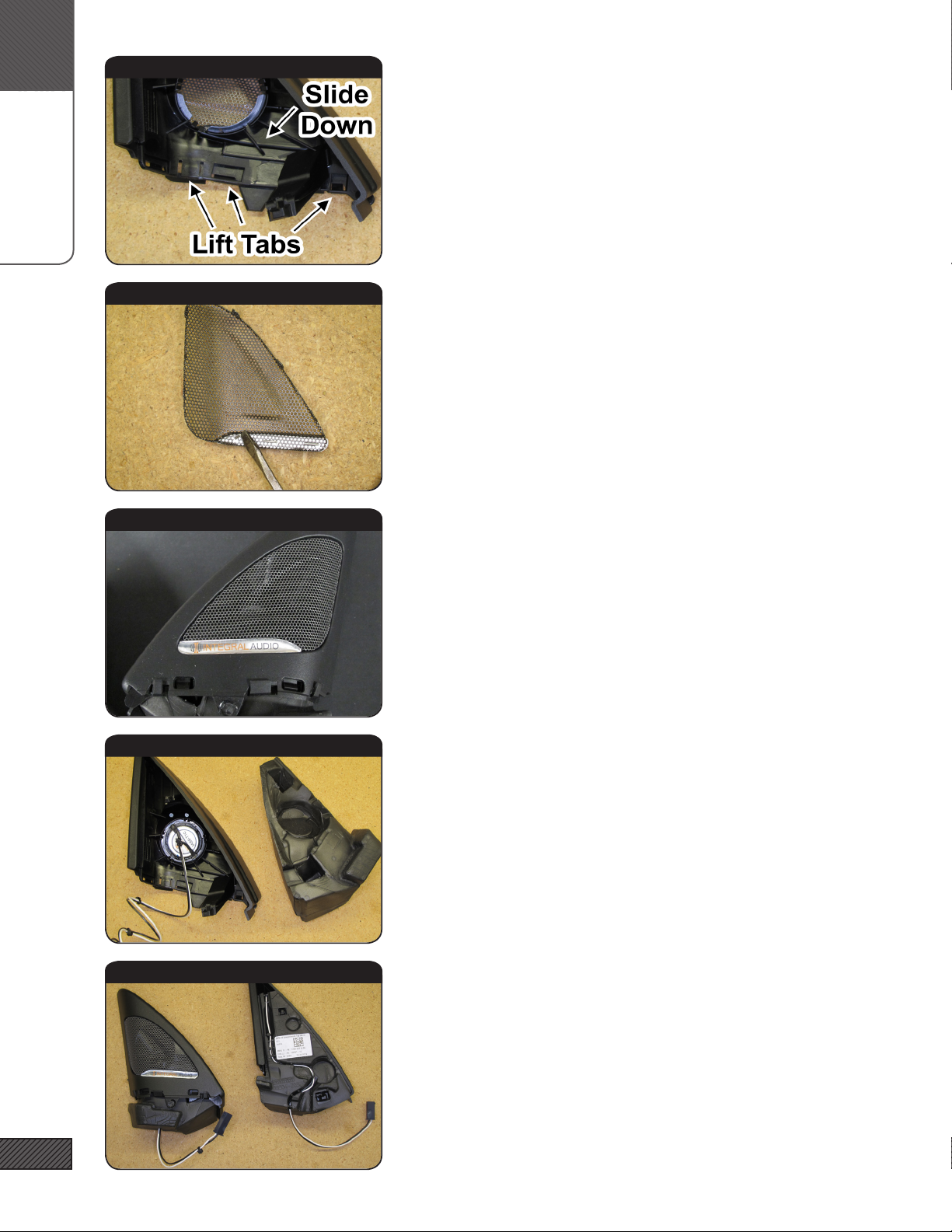
46. TWEETER LOGO BADGES (STEP 1)
Remove the inner portion of the trim panel by lifting the tabs
indicated and sliding the inner portion down and off
47. TWEETER LOGO BADGES (STEP 2)
Remove the hk badges by prying up the locking metal tabs (grille
shown removed for clarity - grille does not remove on all models)
48. TWEETER LOGO BADGES (STEP 3)
Afx the Integral Audio tweeter badges and replace the tweeter
grille (if removed). Replace the inner portion of the mirror sail
trim.
49. INSTALL IASS-T1C TWEETER
Press the IASS-T1C tweeter into the housing, it will snap right in.
50. INSTALL IASS-T1C TWEETER (STEP 2)
Re-insert the foam backing piece. Route the tweeter wiring pig-
tail around and into the channel in the foam.
[HARMAN/KARDON O N LY ]
[HARMAN/KARDON O N LY ]
[HARMAN/KARDON O N LY ]
[HARMAN/KARDON O N LY ]
[HARMAN/KARDON O N LY ]

A.
INSTALLATION
15
51. REPLACE MIROR SAIL TRIM
Replace the mirror sail trim. Be sure the tweeter pigtail wiring
runs clear at the bottom.
52. MOUNT MIDRANGE/TWEETER CROSSOVER (STEP 1)
The midrange/tweeter crossover mounting is extremely simple - it
is wrapped in water-jet cut foam and is a pressure t into the door
panel. The foam wraps around the crossover with the “T” shaped
section covering the vertical inductor. The foam on the side that
inserts into the door rst (1) should rest on top of the other foam.
The pressure from being inserted into the compartment then
holds the foam and crossover in place.
53. MOUNT MIDRANGE/TWEETER CROSSOVER (STEP 2)
Identify the location for the crossover (see next step). Simply
press t the wrapped crossover into the location.
We’ve developed many different types of crossover mounting for
the doors over the years, this is what we’ve found to be the most
secure, reliable, and the simplest/easiest as well!
54.MOUNT CROSSOVER/CONNECT WIRING HARNESS
The location for the crossover is shown at (1).
Run the wiring harness along the bottom of the door and up to
the factory connection point. Be sure all wiring is clear of the
midrange driver and clear of door panel mounting points. Con-
nect the midrange, tweeter, and factory connectors to the harness
55. REPLACE DOOR PANEL
Insert door lock indicator (1) thru hole. Then align the ve clips
along the top of the panel (2). Wiggle the panel slightly to be sure
all clips are aligned. Give a rm strike over each clip to lock in
place. Repeat for the remaining door clips. TIP: a bit of masking
tape on the panel in the location of the clips can help locate them.
Do not nish re-installing the panel until after testing!
REPEAT PREVIOUS STEPS FOR THE PASSENGER SIDE

A.
INSTALLATION
16
56. SETTINGS
In the vehicle audio settings, center fade and balance, set all bass/
treble and equalization to neutral (no boost or cuts), and turn off
L o g i c 7.
57. SET BASS & TREBLE TO FLAT
From the music control section in the headunit, select TONE ->
BASS. Set the bass level to at (centered dial). Repeat for TREBLE.
These are cricial! Center the BALANCE and FADER
Select TONE -> VOLUME SETTINGS -> GONG. Set the gong vol-
ume to the lowest level. You can adjust this back up to preference
later.
58.SET AUX INPUT LEVELS
If you use any device (mp3 player, sat radio receiver, etc) that uses
a headphone out jack as input to the AUX IN, set the volume on
that device to approx. 80-90% of full volume. Adjust the AUX IN
level setting in the headunit to around 60-80% of full volume.
From the music control section in the headunit, select TONE ->
VOLUME SETTINGS -> AUX INPUT LEVEL and set the level.
59. CONFIRM SPEAKER CONNECTIONS & SETTINGS
In the headunit, turn the Balance control to fade full Left. Start-
ing with a 20Hz tone, play each higher frequency up to about
4kHz. You should hear only the subwoofer rst, then at ~50Hz
you’ll transition to the underseat woofer, at ~150Hz to the mid-
range, and the tweeter at ~2.5kHz. You should hear each speaker
on the left, in the correct order. You may get some sound from
the right, but it should be low level. Fade Balance full Right and
repeat the process. When complete, center Balance & Fade.
60. ROCK. AND ROLL.
Reinstall any remaining trim panels, seats, etc, in the reverse
order they were removed.
That’s it! You should be ready to rock and roll. If you aren’t
seriously impressed by the sound, something is wrong. Trust us
on this. It should be clean, clear, and balanced. If it isn’t, revisit
the steps above or reach out to us for support at 646-926-0011 or
email us at support@integralaudio.com.
SETTINGS
Verify that each speaker is
playing correctly.

A.
INSTALLATION
17

NOTES
18
NOTES
• AMPLIFIER TURN-ON: You will notice that the amplier turns on before the head unit, and remains on
after the head unit is off. This is normal. The sound output system needs to be energized to play your
door chimes, parking distance control sounds, bluetooth, etc. The amp will turn on from the moment
the doors are unlocked or opened, and remain on from between 30 seconds and as much as 20 minutes
after the car is locked. Again, this is perfectly normal. The idle current on the ARC amp is virtually
zero and will not cause any issues with battery drain.
• SIGNAL SOURCE QUALITY: A poor quality signal will always sound poor no matter how good an audio
system is. If you are using MP3s or home-burned CDs it is critical that you understand the limitations
and impacts of digital compression methods. MP3s at less than 256kbps will have noticeable loss of
quality. Satellite radio is also compressed and will have similar quality issues. Non-commercially ob-
tained music (especially downloaded via P2P le-sharing) recordings are often re-mixed by third parties
and will have been compressed in an unknown and uncontrolled manner. If you want good quality
sound, use only commercially obtained CDs or MP3s compressed at 256kbps or 320kbps.
• FACTORY RADIO SETTINGS: Please note that the settings (Bass, Treble, Fade, Balance, AUX input level,
etc.) are stored to each Key FOB & are specic to the Source (Radio, CD, AUX) for many vehicles. You
will need to edit and save the settings for each source and each FOB to have consistent sound.
• PLEASE LISTEN RESPONSIBLY: Your new Integral Audio system is capable of delivering Sound Pressure
Levels that can damage your hearing. It also delivers very clean, low-distortion sound reproduction.
Because distortion sounds bad to your ears, and low-distortion sounds good, you are much more likely
to listen at high levels with your new system. Please exercise caution - we want you to enjoy a lifetime
of great sound!
Having Trouble? The best thing to do is contact us at support@integralaudio.
com or give us a call at (646) 926-0011. We’ll get you fixed up ASAP!
TROUBLESHOOTING
Other Integral Audio Car Stereo System manuals


