Integral Audio IASS-T User manual

SKILL LEVEL REQUIRED APPLIES TO
INSTALLATION DIFFICULTY
INSTALLATION TIME
3 OUT OF 5
DO-IT-YOURSELF
6-8 HOURS
2007+ R55 STANDARD 6 SPEAKER
2007+ R55 HIFI/HK
OVERVIEW ........................................................................................................................................ 2
BEFORE YOU BEGIN .......................................................................................................................... 2
WHAT’S IN THE BOX - SOUNDSTAGE.................................................................................................. 3
WHAT’S IN THE BOX - SUBWOOFER................................................................................................... 4
TOOLS YOU WILL NEED...................................................................................................................... 5
INSTALLATION:
A. Prep Vehicle ........................................................................................................................ 6
B. Power & Ground Wiring........................................................................................................ 7
C. Signal Wiring....................................................................................................................... 8
D. Amplifier Installation & Speaker wiring............................................................................... 9
E. Soundstage speaker installation....................................................................................... 11
F. Install the Subwoofer [sub only]........................................................................................ 14
G. Testing & Recommended Initial Settings .......................................................................... 16
TIPS & TUNING................................................................................................................................ 18
TROUBLESHOOTING......................................................................................................................... 18
INSTALLATION GUIDE
SOUNDSTAGE + SUBWOOFER SYSTEM
MINI COOPER CLUBMAN (R55) ver. 5/2017

BEFORE YOU BEGIN
2
•Read this Guide completely BEFORE you begin.
•Disconnect the battery negative terminal while working on the vehicle.
•DO NOT PLACE THE KEY FOB in the vehicle with the battery connected and
the seat airbag wiring disconnected. Doing so will set off the airbag light,
and must be reset by your dealer.
•ALWAYS check behind panels and components before drilling, cutting,
or screwing into any part of a vehicle.
•This guide covers several different vehicle models and options. Some
steps only apply to certain installations. Steps images are labeled with
a black bar across the top:
-[6SPK ONLY] apply only to vehicles equipped with the standard 6 speaker audio system.
-[HIFI/HK ONLY] apply only to vehicles equipped with the upgraded 10 speaker HIFI and
Harmon Kardon audio system. If the vehicle has tweeters in the A-pillar (near the bottom
outer corners of the windshield), you have the HIFI or HK systems.
-[SUB ONLY] apply only if you are installing the Integral Audio Subwoofer System
-If there is no label, the step applies to ALL installations
-Because each kit applies to more than one vehicle, your kit may include extra items.
IMPORTANT

WHAT’S IN THE BOX
3
SOUNDSTAGE
I. SOUNDSTAGE SPEAKER PACKAGE
1. IASS-T 1” Silk Dome Tweeter (Pair)
2. IASS-4 4” Midrange (Pair)
3. IASS-6 6” Midwoofer (Pair)
II. SOUNDSTAGE CROSSOVER NETWORKS WITH VEHICLE-SPECIFIC
TUNING & EQUALIZATION
4. MCSS630MW Mid-Woofer Network (Pair)
5. MCSS630T Tweeter Network (Pair)
III. ARC AUDIO KS MINI AMPLIFIER (2CH W/SOUNDSTAGE, 4CH W/
SOUNDSTAGE + SUBWOOFER)
IV. SIGNAL & SPEAKER WIRING HARNESSES
6. Signal Wiring Harness (MCWH-SIG-R)
7. Mid-Woofer Connection Harness (Pair)
8. Tweeter Pigtail (Pair)
V. SOUNDSTAGE HARDWARE
9. Midrange Mounting Adapter (Pair)
10. Midwoofer Mounting Adapter (Pair)
11. #8 x 1/2” Midwoofer Mounting Screws (12)
12. #6 x 3/8” Midrange Mounting Screws (12)
13. Integral Audio Logo Badge (Pair)
VI. AMPLIFIER INSTALLATION & WIRING
14. Amplfier Power Wiring Harness (complete)
15. Threadlock Wire Splice Connectors (4) [HIFI/HK ONLY]
16. Threadlock Wire Tap (1)
17. Cable Ties (10)
18. 3M Electrical Tape
VII. AMPLIFIER MOUNTING (UNDERSEAT AMP MOUNT)
19. Amplifier Mounting Bracket
20. #6 x 3/8” Pan Head Screw (4)
VIII. MULTIFUNCTION BOX COVER (UNDERSEAT COVER) [OPTIONAL}
IX. FACTORY A-PILLAR TRIM W/TWEETER MOUNTS [OPTIONAL]
Continued on the next page . . .

WHAT’S IN THE BOX
4
SUBWOOFER
X. MC800S SUBWOOFER ENCLOSURE
XI. INTEGRAL AUDIO ALCHEMY 10” SUBWOOFER
XII. SPARE TIRE WELL COVER PANEL
XIII. SUBWOOFER HARDWARE
21. Neutrik Speak-On Terminal & Gasket
22. ¼” x 1” Hex Head Bolt
23. #10 x 1” Black Pan Head Screw (8)
24. #10 x ¾” Pan Head Screw (8)
25. #4 x ½” Black Flathead Screw (2)
26. Threaded Insert (3)
27. Threaded Insert Installation Wrench
28. Subwoofer Mounting Bracket (2)
29. Rosette Thumbscrew (2)
30. Connection Harness (Sub to Neutrik)
XIV. REMOTE LEVEL CONTROL
31. Integral Audio Remote Level Control
32. 3M VHB Double-Sided Mounting Tape (3in)
SeSelect Hardware for Identification:
22 24
26
2012112523
16
27
15

TOOLS YOU WILL NEED
5IMAGES NOT TO SCALE
I. PLASTIC PANEL REMOVAL TOOLS
II. TORX BITS:
1. T25
2. T30
3. T40
4. T50
III. DRILL
IV. DRILL BIT:
5. 7/16” [MUST be correct size!]
V. WRENCHES OR SOCKETS:
6. 7/16”
7. 8mm
8. 10mm
9. 10mm Deep [optional}
10. 19mm
VI. ELECTRICIAN’S WIRE FISH
VII. SCISSORS
VIII. UTILITY KNIFE
IX. PLIERS
X. DIGITAL MULTIMETER
XI. TEST TONE CD (availble for download at
www.integralaudio.com/other_files/test_cd/)
XII. CENTER PUNCH [SUB ONLY]
XIII. STIFF PUTTY KNIFE OR 5-IN-1 [SUB ONLY]
XIV. WIRE STRIPPER [HIFI/HK ONLY]
XV. PICK & HOOK SET [OPTIONAL]
XVI. MAGNETIC PARTS TRAY [OPTIONAL]

A.
PREP VEHICLE
6
1. REMOVE PASSENGER SEAT
Slide the seat forward. Using a Torx T-40, remove the two screws
holding the rear of the seat (1). Slide the seat backward and re-
peat for the two front screws.
2. REMOVE PASSENGER SEAT (PART 2)
Tilt the seat back. Disconnect the airbag wiring under the seat by
pulling the black slide catch on the side of the yellow plug. Dis-
connect the seat heater wiring if equipped. DO NOT put the key
FOB in the ignition while this plug is disconnected. Remove the
seat from the vehicle.
3. REMOVE PASSENGER SEAT (PART 3)
If present, remove the plastic panel under the seat.
4. REMOVE DRIVER SEAT
Repeat the previous steps to remove the Driver seat.
[This step is not absolutely necessary, but it does make later steps
easier and is recommended.]
5. REMOVE LEFT DOOR SILL TRIM (PART 1)
Using a Torx T-50 bit, remove the seat belt screw (1) where it
passes through the rear of the door sill trim.
SEE PREVIOUS
IMAGES

B.
POWER & GROUND WIRING
7
6. REMOVE LEFT DOOR SILL TRIM (PART 2)
Remove metal seat belt bushing (1) if not removed in the previous
step. Pull Rear Side Trim Panel (4) in, releasing clip (3) and freeing
tab of Door Sill (2) located behind Side Panel (4).
7. REMOVE LEFT DOOR SILL TRIM (PART 3)
[Seat shown removed for clarity]
Remove the door seal over the entire length of the right door sill
by lifting it up and off. Pull up/loosen the rubber door seal gas-
ket along the length of the door. Pull Door Sill Panel (2) inward,
releasing clips (3). This requires a rm pull at each of the clip
locations. Remove the small trim piece (1) by pulling it toward
the rear of the vehicle, releasing spring clip.
8. REMOVE THE RIGHT DOOR SILL TRIM
Repeat the previous three steps for the Right Side of the vehicle.
9. RELEASE FRONT OF THE REAR SEAT BOTTOM
Pull up rmly on the front of the edge of the rear seat bottom to
release. This will allow you access underneath the carpet in later
steps.
10. POWER & GROUND WIRING (OVERVIEW)
The 12V+ wire runs directly from the battery to the new amplier
that installs under the passenger seat. An inline fuse is installed
at the battery.
The Ground wire runs from the amplier to one of the factory-
installed common ground points along the door sill
SEE PREVIOUS
IMAGES

B.
POWER & GROUND WIRING
8
11. REMOVE RIGHT COWL PANEL
Open the Bonnet (aka the hood!). Remove the black plastic Cowl
covering the battery by releasing nuts (2) and (3) with a 10mm
socket. Loosen & remove cowl.
NOTE: When replacing the cowl, be sure the seal (1) is seated
properly and that the secondary tab of the cowl (4) is inserted into
the plastic channel (5) that attaches to the bottom of the wind-
shield.
12. REMOVE THRU-WALL COVER
Remove the battery.
Locate the thru-wall bushing behind the battery. Using a at
screwdriver, release the indicated retaining tabs then remove the
plastic thru-wall cover to expose the thru-wall opening.
13. POWER WIRE
Locate the Power Wire (with fuse holder) in the amp wiring kit.
REMOVE THE FUSE IF INSTALLED IN THE HOLDER! Feed the Red
Power Wire through the spare wiring nipple and into the cabin.
From inside the vehicle, locate the wire coming in. Feed the wire
around the fuse box and along the Right Door Sill.
Remove the auxiliary nut on the battery post with a 19mm socket
and attach the ring terminal on the end of the power wire.
14. GROUND WIRE
Locate the Common Ground point under the Right Door Sill. Re-
move the nut with a 10mm socket. Attach the ring terminal of
the Black Ground Wire to the Common Ground point.
NOTE: On some vehicles the common ground is located a bit
further forward. Enough ground wire is included to reach either
location.
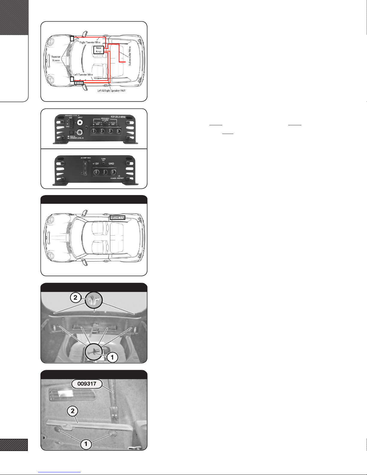
15. SIGNAL WIRING HARNESS (OVERVIEW)
The signal wiring harness contains all wiring for low and high
level signals, remote volume, and remote turn on. Items are:
(1) X9331 T-harness; (2) Remote turn-on wire; (3) Subwoofer
remote volume control; (4) Left Tweeter speaker wire; (5) Right
Tweeter speaker wire; (6) Subwoofer speaker wire; (7) RCA &
Speaker wire connections to ARC Amplier; (8) Inline labels for
HIFI/HK systems

C.
SIGNAL WIRING
9
16. SIGNAL WIRING (OVERVIEW)
The factory audio signal is obtained from the X9331 connector in
the driver-side footwell, described below. The X9331 T-harness
portion of the signal wiring harness plugs into each side of the
factory connector, and sends the signal to and from the new ARC
amplier in the rear. The ‘remote volume’ branch of the harness
is routed to the center console.
17. ACCESS X9331 & X15 CONNECTORS
Locate these connectors in the left footwell, above the dead pedal.
The X9331 is behind and attached to the larger X15. Remove
both by twisting counter-clockwise ¼ turn and pulling outwards.
Separate the X9331 from the X15 by releasing the locking tabs on
the connector joining them.
18. CONNECT X9331 T-HARNESS
Unplug the X9331 connector and connect the T-Harness. The RCA
Jacks are the OUTPUT from the factory stereo - in later steps they
will be connected to the INPUT on the remote level control [sub
only] and the amplier. Red = Right Channel, White = Left Chan-
nel. Both reds and both whites carry the same signal and are
interchangable. The stripped wire ends are SPEAKER INPUT and
will be connected to the amplier OUTPUT. The left channel is
labeled.
19. REMOTE LEVEL CONTROL
[SUB ONLY]
[NOTE: IF YOU PLAN TO INSTALL THE SUBWOOFER LATER, GO
AHEAD AND RUN THIS CABLE NOW]
Locate the Remote Volume control cable. Pull rmly on the top
of the plastic panel under the steering wheel to release the top
edge of the panel. Feed the Remote Volume cable along and un-
der the knee bolster.
20. REMOVE FOOTWELL PANEL
[SUB ONLY]
Remove the panel next to gas pedal by releasing the Torx T-25
screws (some vehicles have phillips head screws) and pulling the
panel out and towards the rear of the vehicle.
[SUB O N LY ]
[SUB O N LY ]

C.
SIGNAL WIRING
10
21. ROUTE REMOTE LEVEL CONTROL
[SUB ONLY]
Run the Remote Level Control cable above the metal shown and
then thru the gap under the bottom edge of the center console.
. REMOTE LEVEL CONTROL
[SUB ONLY]
Assemble the Remote Level Control by inserting shaft-rst into
the housing and fastening with the washers and nut. Slide the
knob over the shaft.
Attach the 3M VHB double-sided adhesive (this is the green 3in
length) to the top of the Remote Level Control housing. Trim ex-
tra length from the VHB, if necessary. Wipe the surface with one
of the Alcohol Prep Pads before applying.
22. MOUNT REMOTE LEVEL CONTROL
[SUB ONLY]
Connect the cable to the Remote Level Control. Mount the Re-
mote Level Control below the toggle switches. Wipe the surface
with the Alcohol Prep Pad before applying.
Do a dry-run to check the placement and be sure you know
exactly where you’d like the control. You will nd that you can
place it more toward the front of the recess for easier access, or
toward the rear for a more hidden look.
23. CUT & RELEASE MID/MIDWOOFER SPEAKER WIRES
[HIFI/HK ONLY] [HIFI/HK ONLY] [HIFI/HK ONLY] [HIFI/HK ONLY]
For HIFI/HK equipped vehicles ONLY!
Cut the Mid/Woofer Speaker wires at the X9331 T-Harness.
Remove the wires from the rest of the harness bundle UP TO
WITHIN 8 FEET OF THE RCAS at the other end of the harness.
These wires will be used later to connect to the factory wiring
downstream of the HIFI/HK amplier.
24. REMOTE TURN-ON WIRE
Identify the solid black wire coming out of pin 1 of the X15 con-
nector (from previous step). Locate the 18AWG White Remote
turn-on Lead wire in the signal harness. Unscrew both ends
of the Threadlock wiretap (the tap has a hole in only one end)
Slip the “U”-shaped bottom around the signal wire to be tapped.
Carefully thread the body of the tap onto this and tighten rmly.
Be sure not to cross-thread the tap.
[SUB O N LY ]
[SUB O N LY ]
[SUB O N LY ]
[HIFI/HK O N LY ]

C.
SIGNAL WIRING
11
25. RUN SIGNAL WIRING TO AMP
Beginning in the left (driver’s) side footwell, run the amplier
end of the signal wiring bundle along the door sill, and under
the carpet in the rear seat footwell area.power/ground wires. Be
sure the wiring is clear of all pinch points, including the Seat Belt
screw.
AVOID PLACING SIGNAL WIRING DIRECTLY ADJACENT TO OR
TOUCHING OTHER WIRING BUNDLES!
26. AMPLIFIER MOUNTING (OVERVIEW)
The amplier mounts in the compartment under the passenger
seat. If your vehicle does not have a compartment with cover un-
der the seat, one has been included in your kit. You will cut the
carpet, remove the foam block inside, and then mount the amp.
27. TRIM CARPET FOR COMPARTMENT COVER
[FOR VEHICLES WITH CARPET UNDER SEAT]
Lay the Multifunction Box Cover on the area underseat. Mark
where the carpet needs to be cut with tape. Cut carpet and foam
backing with a utility knife. Cut CAREFULLY - there are wires
along the front edge of the compartment. The carpet should be
cut SMALLER than the cover or there will be exposed area. If in
doubt, remove the drivers seat and compare to the factory cut.
Notch the carpet in the mounting screw areas.
28. REMOVE THE PLASTIC TUB
[FOR VEHICLES WITH EXISTING PLASTIC COVER]
Remove the plastic tub liner from the compartment. Detach any
equipment mounted to it.
DO NOT remove or remount the DSC module (see image)
29. ATTACH AMPLIFIER MOUNTING PLATE
Cut strips of the 3M Double-Sided Foam Mounting tape and afx
one side to the back of the amp mounting plate and any original
equipment from the underseat compartment. Arrange all compo-
nents so that they t. Clean all components and the sheet metal
with an Alcohol Prep Pad prior to attaching the Foam Mounting
Tape.
D.
SOUNDSTAGE
12
30. SPEAKER WIRING (OVERVIEW)
The front channels of the ARC amplier drive the front tweeter
and midrange/midwoofer in parallel. The rear channels drive
the subwoofer. The factory HU/Amp continues to drive the rear
ll speakers. In Standard 6 speaker vehicles, the signal wiring
harness feeds the door midrange and midwoofer via the X9331 T-
harness. In HiFi/HK equipped vehicles, a separate connection is
made to the factory wiring downstream of the HiFi/HK amplier.
There are separate wires for the tweeters in all vehicles.
31. AMPLIFIER TO SPEAKER OUTPUT CONNECTIONS
Connect BOTH the Left Tweeter wire AND the Left Midrange/
Midwoofer wires to the Left channel of the ARC ampler. Repeat
for the right channel. YOU WILL HAVE TWO WIRES IN EACH OF
THE HOLES.
[SUB ONLY] Connect the Subwoofer wire to the rear channels in
the “bridged” conguration as shown on amp. YOU WILL HAVE
ONE WIRE IN EACH OF THE OUTER HOLES.
NOTE: 2ch amp shown. The 4ch has 2 rows of speaker outputs.
32. HIFI/HK SPEAKER WIRE CONNECTIONS
[HIFI/HK ONLY]
The midrange/midwoofer wires on the HIFI/HK do not pass thru
the X9331 and must be tied in at the factory amplier located in
the passenger side quarter panel.
The next steps will guide you thru accessing the HIFI/HK ampli-
er and making the proper connections.
33. REMOVE REAR SILL TRIM
[HIFI/HK ONLY]
Pry out the center pin of expansion rivets (1). Remove the rear
sill trim by lifting up, releasing clips (2).
34. REMOVE RIGHT WHEEL ARCH TRIM (PART 1)
[HIFI/HK ONLY]
Pry off cover guide (2) with a prybar or BMW tool 009317. Unclip
covers (1) and remove screws underneath.
[HIFI/HK O N LY ]
[HIFI/HK O N LY ]
[HIFI/HK O N LY ]

D.
SOUNDSTAGE
13
35. REMOVE LEFT WHEEL ARCH TRIM (PART 2)
[HIFI/HK ONLY]
Release expansion rivets (1) by prying out center pin. The trim
panel (2) should open enough to access the amplier.
*Left side is pictured, procedure for right side is the same.
36. ACCESS FACTORY AMP & WIRE LOOM
[HIFI/HK ONLY]
Remove screw (1) with a 10mm socket. Slide amp (2) towards the
rear to release. Unplug amplier connector to access wire loom.
Cut wrapping as needed to access wiring. Do not forget to recon-
nect the factory amplier after making the speaker connections.
37. HIFI/HK SPEAKER WIRE CONNECTIONS
[HIFI/HK ONLY]
Refer to the chart below. Cut, strip, and connect the wire to the
side coming from the car (NOT the factory amp!).Check pin as-
signments (see following steps) to conrm correct wires - some
vehicles have duplicate color pairs!!
38. HOW TO CONNECT THREADLOCKS
[HIFI/HK ONLY] The Threadlocks will be used in the next steps
for HIFI/HK equipped vehicles. They work like this: Strip 3/8” of
insulation from the wire to be connected. Unscrew one end of
the Threadlock and insert the wire through the end, then tighten.
There should be no exposed wire and the wire should be secured
thightly in the connector. These form a mechanical connection
that is easily reversible and more reliable than a soldered con-
nection.
[HIFI/HK O N LY ]
[HIFI/HK O N LY ]
[HIFI/HK O N LY ]
HIFI/HK SPEAKER OUTPUT CONNECTIONS
SIGNAL WIRE COLOR PIN CONNECT TO AMP
Front Left ++ Blue w/White Stripe 33 Front Left ++
Front Left -- Blue w/Brown Strip 34 Front Left --
Front Right ++ Blue w/Black Stripe 11 Front Right ++
Front Right -- Bue w/Brown Stripe 12 Front Right --
[HIFI/HK O N LY ]

D.
SOUNDSTAGE
14
39. HOW TO CHECK HIFI/HK PIN NUMBERS
[HIFI/HK ONLY]
Unplug the factory ampler connector by releasing the locking
lever. Gently pry the black plastic housing out to release the
locking tab.
Slide the inner connectors out of the housing. You will see the
pin numbers marked on the housing. Verify with the chart above
40. AMPLIFIER POWER & SIGNAL CONNECTIONS
Connect the Power, Ground, and Remote Turn-on Lead wires to
the amplier.
Connect the RCA Interconnects. Set the INPUT selector on the
amp to “RCA” (2ch amp) or “LOW” (4ch amp)
Attach the amplier to the mounting plate using the #6 x 3/8”
screws.
[SUB ONLY] Connect the RCA’s labeled “SUB” to the Rear Inputs of
the amplier.
41. REMOVE DOOR HANDLE TRIM RING
Pull pin (1). Leave trim ring (2) in place, it will come off when you
remove the door panel.
42. REMOVE PUDDLE LIGHT
Pry out Puddle Light (1) from bottom of door. Disconnect and set
aside.
43. REMOVE DOOR PANEL
Remove door panel (1) by pulling rmly inward to release clips
(2). Begin at the bottom rear corner and work your way around.
Use a plastic panel removal tool to help you get started. The Door
Handle Trim Ring will come off with the panel. Set aside with
the pin removed earlier - it will snap on after you replace the door
panel. Be aware of the door lock indicator on the top/rear when
removing the door panel - lift the panel up and over to clear the
indicator!
[HIFI/HK O N LY ]

D.
SOUNDSTAGE
15
44. REMOVE MIRROR CONTROL
Carefully pry the Mirror Control (2) up at the bottom rear. Once it
releases wiggle it up and out. Unplug connectors (1) and set aside.
45. MIDRANGE COVER
Pull rmly up and in on the Midrange Cover (1) while pressing
inward at the locations of the tabs (2). It is better to pull rmly
than to try to pry at the tab locations. Give it a rm pull, it will
pop free!
46. REMOVE DOOR SPEAKERS
Remove the woofer mounting screws (1) with a Torx T-25. Unplug
the speaker connector (2). Repeat for the door midrange.
Keep the Torx screws - they will be used to mount the new speak-
er adapters.
47. REMOVE ARMREST COVER & TRIM
Remove Armrest Cover (1) by levering up the edges of the trim in
the directions indicated by the arrows.
Remove the trim cover (2) by releasing the two Torx-25 screws at
either end.
48. MIDRANGE/MIDWOOFER (OVERVIEW)
The Midrange/Midwoofer crossover network (1) installs in the cav-
ity behind the door armrest cover. The wiring harness connects
to the factory midrange connector (blue). The wiring harness is
routed behind the armrest trim and through the hole at the back
of the midrange cover to the factory connector and the midrange
driver. The wire for the woofer continues behind the midrange,
down and through the rubber grommet and on to the back of the
midwoofer.

D.
SOUNDSTAGAE
16
49. COVER CROSSOVERS WITH FOAM PADDING
The crossovers get wrapped in foam padding, secured by zipties.
The square pieces of foam are for the midrange/midwoofer cross-
over, the narrow rectangular pieces are for the tweeter crossovers
50. COVER CROSSOVERS WITH FOAM PADDING
Place each crossover component-side down. You want the seam
of the foam to be on the smooth printed circuit board side of the
crossover. Make sure the terminal connections for the wiring
harness are on the open end.
51. COVER CROSSOVERS WITH FOAM PADDING
Wrap the foam around each crossover and secure with (3) zip-
ties for the midrange/midwoofer crossover, and (2) zipties for the
tweeter crossover
52. MIDRANGE/MIDWOOFER WIRE HARNESS
The wiring harness for the speaker and crossover connections to
the door speakers has been pre-fabricated. Connector (1) will plug
directly into the factory midrange connector. The 18” branch (3)
connects to the midrange driver. The 36” branch (4) connects to
the woofer. The stripped ends (2) connect to the crossover in the
armrest.
53. ROUTE & CONNECT WIRE HARNESS
Route all wires through the opening (1) at the rear of the mid-
range cavity. Connect the blue connector to the factory midrange
connector. Leave the midrange wire in the midrange cavity. Con-
tinue running the woofer wire behind the midrange cavity, then
out and down to the rubber grommet (2). Using a utility knife, cut
a small slit in the grommet and run the woofer wire through and
into the door cavity. Be certain all wires are clear of any moving
parts or obstructions!

D.
SOUNDSTAGE
17
54. CROSSOVER CONNECTIONS
Connect the stripped wires ends to the crossover board. The
branch from the blue connector connects to the “IN”. The mid-
range branch connects to “M”, and the woofer branch connects to
“W”. Red is + and Black is - for all three.
Place the Crossover in the armrest cavity. The armrest cover will
hold it in place. IMPORTANT: on some 2013+ models, there may
be a plastic screw boss in the way. This screw boss can be cut
away if it interferes with crossover placement.
55. MOUNT MIDRANGE & MIDWOOFER
Mount the Woofer Adapter to the door with the factory Torx
screws removed earlier. Connect the woofer wiring, making sure
the connectors lock to the speaker tabs. Use wire ties to ensure
that the woofer wiring is clear of the window mechanism! Mount
the woofer with the #8 x 1/2” black oxide screws.
Repeat the process for the Midrange, using the #6 x 3/8” screws.
56. TWEETER INSTALLATION (OVERVIEW)
The Soundstage Tweeters install directly into the factory tweeter
mounts on the A-Pillar trim (the trim at either side of the wind-
shield). The tweeter crossover networks install in a small com-
partment on either side of the dashboard. The crossover input
connects to the tweeter wire from the amp and the 18” tweeter
pigtail connects to crossover to the tweeter.
[6SPK ONLY] The new A-pillar trim is included
57. REMOVE A-PILLAR TRIM
Carefully lever/pry out screw cap cover (1). Remove the T-20 Torx
screw underneath. Loosen the door seal (4) to gain access to the
edge of the trim piece (3). Pull inward to release clips (2). Discon-
nect the tweeter wire and remove the the trim piece.
[6SPK ONLY] You will not be reusing this trim piece
[HIFI/HK ONLY] You WILL be reusing this trim piece.
58. REMOVE EXISTING TWEETER
[HIFI/HK ONLY]
Release tabs (1) and remove tweeter (2). Unclip capacitor and wire
(3) and remove.
[HIFI/HK O N LY ]

E.
SUBWOOFER
18
59. REMOVE/REPLACE TWEETER BADGES
[2010+ HK ONLY]
Remove the “Harmon/Kardon” tweeter badge by prying up gently
with a at screwdriver. You need to insert the blade into the thin
gap between the badge and the backing plate, not between the
backing plate and the grill material. Replace with the adhesive
Integral Audio badge by removing the backing and afxing in the
recess in the tweeter grille.
60. INSTALL TWEETER
Press the new tweeter squarely and rmly into the housing until
it locks into place. The “I” logo should be vertical.
NOTE: On some cars the tweeter mount may be warped, making
a very tight t. If you can’t get all the tweeter latches to lock, use
a small dab of cyanoacrylate (superglue) at the tab location.
61. OPEN DASHBOARD SIDE COMPARTMENT
Using a panel removal tool, lever open the plastic cover on the
side of the dashboard. Run the tweeter wire coming from the
amp up the side of the door jam and into this compartment.
62. INSTALL & CONNECT TWEETER CROSSOVER
Connect the tweeter wire from the amp to the “IN” terminals on
the tweeter crossover. Connect the 18” Tweeter Pigtail to the “T”
outputs. Route the pigtail up to the base of the A-pillar for con-
nection to the tweeter. Place tweeter crossover (1) into compart-
ment.
63. REPLACE A-PILLAR
Connect the tweeter wire pigtail to the tweeter (4).Replace the
A-pillar trim (1). Take care to ensure that the tabs (3) and clips (2)
align with their corresponding holes on the vehicle, and that the
clear rubber sleeves are protecting the metal tweeter tabs. The
tabs (3) can be a little tricky - it helps to use a panel tool between
the trim and the windshield to force the tabs inward and into the
holes. Do not replace the screw and screw cover yet (wait until
after testing!)
[ 2 010 + HIFI/HK O N LY ]

E.
SUBWOOFER
19
64. REPEAT FOR THE RIGHT SIDE
Repeat all of this section for the other side of the vehicle. Obvi-
ously, you can omit the steps relating to the mirror switch!
65. SUBWOOFER INSTALLATION
This entire section applies only to the subwoofer installation. If
you are not installing the subwoofer system please proceed to
Testing & Recommended Settings.
66. INSTALL NEUTRIK SPEAK-ON PLUG
Split and strip the end of the Subwoofer Speaker wire. Slide the
blue threaded bushing back. Thread the speaker wire through
the bushing and the inner bushing. Loosen the clamping screws,
insert each wire (observing the polarity markings on the connec-
tor), and tighten the screw. Snap the blue threaded bushing back
down and thread down rmly.
67. ATTACH THE MOUNTING BRACKETS
Align the Mounting Brackets over the pre-drilled pilot holes on
the sides of the enclosure and attach using the (8) #10 screws.
68. THREADED INSERTS (OVERVIEW)
Self-Sealing Threaded Inserts are used to secure the enclosure
to the vehicle. It is important that you follow these installation
steps carefully and completely. An extra Insert is provided in
case you run into trouble.
SEE PREVIOUS IMAGES

E.
SUBWOOFER
20
69. REMOVE ASPHALT PATCH
On the driver’s side of the boot oor you will see an approximate-
ly 2” x 2” asphalt patch. Use the stiff putty knife to remove it. It
should remove easily, if not heating it with a heat gun (or hair
dryer) will soften it. Cut a short strip of electrical tape and cover
the hole - the enclosure side leg will sit over the hole.
70. MARK FOR BRACKET AND THREADED INSERT
Temporarily replace the Wheel Arch Trim Panels, if previously
removed. Place the enclosure in the boot, all the way forward and
centered side-to-side in the carpet opening. Using a center punch
(or marker), mark the center of the mounting bracket hole in the
sheet metal below. Keep the hole at least 3/8” away from the
edges of the raised/lowered area of the sheet metal. Cut a notch
in the carpet by cutting two slits and folding the carpet back and
under. Mark the center with a marker or center punch.
71. INSTALL THREADED INSERTS (PART 1)
Using a 7/16” bit (NOT a ½” bit!), drill holes in the 2 positions
marked on the boot oor. Do not let the drill bit penetrate more
than ¼” through the sheet metal. You may nd it helpful to use a
cut-to-length wood block as a stop for the drill. It is important to
drill the holes EXACTLY where they were marked.
Remove any metal burrs - the hole must have clean edges.
72. INSTALL THREADED INSERTS (PART 2)
Using a utility knife, carefully trim the PVC jacket out of the
center of the Self-Sealing Threaded Inserts as shown. Insert the
1” Hex Bolt through the Installation Tool. Then thread the 1” Hex
Bolt into the Threaded Insert. Be sure the “nubs” on the Instal-
lation Tool face the top of the Threaded Insert. These “nubs” are
what grip the Insert and prevent it from turning during installa-
tion.
73. INSTALL THREADED INSERTS (PART 3)
Insert the Threaded Inserts into the holes drilled in the previ-
ous step. Keep the Insert vertical and keep the head of the Insert
ush against the sheet metal and carefully tighten the bolt by
hand with a wrench (do not use a powered tool of any kind) until
you begin to feel resistance and the insert is secure. Take your
time - do not over-tighten. Remove the 1” Hex bolt. If you have
trouble with an Insert, you can remove it by partially unthreading
the 1” Hex bolt and tapping it with a hammer.
This manual suits for next models
4
Table of contents
Other Integral Audio Car Stereo System manuals


