Integrity NexPore CF 7.2 User manual
科百特CF–7.2 完整性测试仪使用指南
!
Integrity Tester CF 7.2
Instruction Manual
CF 7.2IntegrityTester Instruction Manual
Integrity Test Instruments
CF 7.2 Integrity Test
All Integrity Test Methods Are Present: Basic Bubble Point, Enhance Bubble Point,
Diffusion Flow Test, Water Intrusion Test, Pressure Decay Test, and Manual Bubble Point
HD 7” Color Touchscreen Allow for Easy Selection of Testing Parameters
Testing Accuracy Has Been Significantly Improved By Using Advanced Digital
Sensors and Brand New Hardware Design
Dual Core CPU Features Include High Speed and Stability Which Ensure the Efficiency,
Safety, and Stability of the Device While in Use
Detailed Testing Data and Integral Testing Curve Provide An Objective Analysis Report
User-friendly Display Design Make it Easy to Use
Electronic Signature and User Classification Managing
Function Help to Eliminate Erroneous Operation
Optional Data Interface Includes Standard RS232/USB
Port and Simulation Control Port
Customized Communication Protocol Provides Automatic
Centralized Management for Customers
Features and Benets

- 1 -
Important Notice
Important Notice
Please read this user manual carefully before
starting CF7.2 Integrity Tester.
Failure to do so may result in product damage
and/or bodily harm.
NexPore SHALL NOT be held responsible for any
damage caused by failure to comply with this
instruction manual.
For additional information, please contact your
NexPore Sales Engineer.
CF 7.2IntegrityTester Instruction Manual

Table of Contents
Table of Contents
- 2 - - 3 -
CF 7.2IntegrityTester Instruction ManualCF 7.2IntegrityTester Instruction Manual
1. CF 7.2 Integrity Tester Safety Instructions
1.1 Electrical
1.2 Compressed Air Use
1.3 Installation and Testing
1.4 Filter Installation
2. CF 7.2 Integrity Test System
2.1 Basic Characteristics
2.2 Standard Features
3. Test Principle Integrity Testing
4. Instrument Functions and Test Procedures
4.1 Instrument Test Functions
4.2 Introduction to Instrument Interface and Test Process
4.2.1 User Login Interface
4.2.2 Test Program
4.2.3 Self Test
4.2.4 Test
5. System Configuration
5.1 System Parameter
5.2 Date/Time
5.3 Communication Setting
5.4 Battery
5.5 Touchscreen
5.6 User Management
5.7 Audit Trail
6. History
7. Data Printing
8. Printer Installation and Maintenance
8.1 Installing/Replacing Paper
8.2 Installing/Replacing Ribbons
9. Replacing the Main Fuse
10. Instrument Calibration
11. Common Faults and Troubleshooting
1.1 Electrical
1. CF7.2 Integrity Tester Safety Instructions
a. Important Notice: Avoid touching the circuit interface
located at the back of the tester with water or other
liquids.
b. When replacing the fuse, the power plug must be
unplugged from the power supply.
c. All repairs must be completed by maintenance
personnel authorized by NexPore.
d. DO NOT OPEN the Integrity Tester Housing when the
power is turned on.
e. Please make sure that the power cord is connected
before turning the Integrity Tester on.
f. Due to GMP Regulations, NexPore advises customers
to calibrate the Integrity Tester once a year
1.2 Compressed Air Use
a. The operator is responsible for providing clean and dry
compressed air to the Integrity Tester
b. Maximum inlet pressure of the instrument is 8000mbar
c. Pressure resistance on the pressure pipe used must be
≥ 8000mbar
d. Operator MUST carefully check the pressure pipe and
fittings before use.
1.3 Installation and Testing
a. This Integrity Tester is a highly sensitive device. Please
be careful when in use.
b. When installing the Integrity Tester, please ensure that
no test solution accidentally pours into the instrument
c. When using chemicals or performing compressed air
tests, take all necessary precautions.
1.4 Filter Installation
a. The pressure range MUST NOT exceed the normal
working pressure range of the filter housing or capsule
filter.
b. Prior to disassembling, ENSURE that the instrument and
filter pressure have returned to normal.
c. Remove the air line on the high pressure line carefully.
1. When powering the Integrity Tester on, first connect
the power cord to the Integrity Tester first and then to
the external power supply.
2. The power supply MUST be grounded
3. NexPore SHALL NOT repair the Integrity Tester due
to damage caused by dismantling it.
4. Please follow all instructions when testing the
equipment
Additional Remarks
Safety Instructions
- 4 - - 5 -
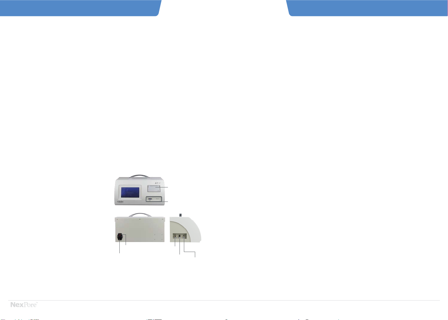
AIR
OUTLET
PRINTER
POWER(ON/OFF)
PLUG EHXHAUST
OUTLET AIR
INLET
EXPORT OUTLET
2.1 Basic Characteristics
2. CF 7.2 Integrity Test System
The instrument includes standard digital and analog
interface (RS232/USB) and customized industrial bus
and analog control ports according to customer needs.
Powerful PC software and customizable communication
protocols provide users with a guarantee of automated
centralized control management.
The R&D team can design specific solutions based upon
customer requirements. With years of on-site experience
and strong professional services, it ensures that the
customers can use the instrument with confidence, and
also provide technical support for the design and
configuration of the customer's filtration system.
CF7.2 Integrity Tester is a compact, light bench-top
instrument weighing 8.2 kg.
User-friendly interface design and modular settings
are easy to use and operate.
Upgrades include new hardware circuit design and
advanced digital sensor technology for accurate and
consistent test results.
The instrument's CPU has industrial-grade dual-core
design. Its high speed and stability ensure the safety,
reliability and speed of the instrument during use, and
solve the instability caused by the operating system. A
high-definition, large-size color touch screen allows
for richer test input data that can be based on different
test parameters including automatic selection and
matching detection program that best fits the current
filter.
The simple and convenient "pre-determined" design
not only improves the integrity of the test parameters,
but also greatly simplifies the user's operation. As a
program, it allows the real implementation of
"one-click completion". Electronic signature and user
hierarchical management facilitate the division of
responsibilities and prevent misuse.
Detailed test data and complete test curves enable
users to comprehensively and accurately analyze
various the performance indicators of the filter under
test to provide users with objective analysis reports.
2.2 Standard Features
a. Basic Bubble Point Test
b. Manual Bubble Point Test
c. Pressure Decay Test
d. Diffusion Flow Test (including microfiltration and ultra-filtration)
e. Enhanced Bubble Point Test (Combination of Diffusion Flow and Basic Bubble Point)
f. Water Flow Test (WFT)
g. Self Test
h. Verification
i. Supports up to 80 Test Plans
j. User Management Hierarchy
k. Print using the Built-in Printer
l. Up to 5000 Test Results can be Stored
m. Display Time and Date
n. Support English and Chinese Input
Test Supplements
a. Support online and offline testing without affecting results
b. System presses the pressure compensation, so the environmental
pressure difference does not affect test results
c. In-line testing only contacts the upstream of the filter and does not
contaminate the downstream of the filter
d. The test results can be generated by the host computer software.
Basic Functions
a. Each test procedure supports pre-pressurization
b. Stored test results can be read and saved by SD card and USB
c. Check reminder
d. Support 4 levels of multiple users
CF 7.2IntegrityTester Instruction ManualCF 7.2IntegrityTester Instruction Manual
Basic Characteristics Standard Features

Pressure Decay Test is also known as the pressure hold
test. During the test, a high-precision pressure gauge or
sensor is used to monitor the pressure change caused
by the diffusion of gas leaking or passing through the
filter. This test has two main uses:
1. to measure the tightness of the filtration system
2. detect filter integrity
3.Tests Principle Integrity Testing
Tests principle Integrity testing methods including diffusion flow test, bubble point test, pressure hold
test, water flow test and enhanced bubble point test in accordance with 21 CFR Part 11. The Integrity
Tester is also complied with the standard requirements of Pharmaceutical Industry.
Tests Principle Integrity Testing
At a certain temperature, the minimum pressure difference
required to vent the largest hole in the wetted filter
membrane is forced by gas.
Bubble Point Test
a. Bubble Point Test
b. Bubble Point Definition
D:
θ:
γ:
the diameter of the largest pores
the contact (“wetting”) angle between the liquid and
the membrane
the surface tension of the wetting liquid
k:correction factor for the shape of the largest pores
P = 4× kcos
D
γ
θ
Pressure
Bubble point
Membrane Membrane MembraneMembrane
× ×
b. Diffusion Flow Definition
Diffusion Flow Test
a. Diffusion Flow Principle
Diffusion Flow refers to the flow of gas through the
pores of the membrane hole driven by a pressure
difference between compressed air and nitrogen on
both sides of the membrane at a pressure below the
bubble point.
The bubble point test is a non-destructive test method
based on the principle of surface tension and capillary
phenomena of liquid in the pores of the filter membrane.
The bubble point detects the minimum pressure
required to overcome these forces and expel the liquid
in the pores of the membrane.
Q = K×H(P1-P2)×R
L
Pressure
Gas molecule
Diffusion
Membrane
Q:
K:
H:
Diffusion Flow (throughput per unit time)
membrane-specific correction factor
Henry's law coefficient 1
P1:
R:
L:
inlet side pressure
ideal gas constant
length of diffusion path
P2:outlet side pressure
- 6 - - 7 -
Water Flow Test
a. Water Flow Principle
The water flow method complies with the FDA's
integrity testing requirements for sterilizing grade
filters. It can be associated with bacterial challenge
experiments. The water flow test is a highly sensitive
method of performing hydrophobic membrane
integrity testing based on water flow without alcohol.
Since the filter is not wetted and is almost dry, it can be
blown (baked) after the integrity test is completed and
put into use.
Pressure Decay Test
a. Pressure Decay Principle
The diffusion flow test can also be approximated by
measuring the pressure decay of the filter. After a
certain period of time, the attenuation value can be
measured to determine the integrity of the filter.
Calculated as follows:
b.Water Flow Definition
The minimum pressure difference between the
maximum pores of the hydrophobic membrane.
(In general, the water flow value is tested by
means of constant pressure water flow, similar
to the diffusion flow test),
△P × V
DF = Pa × T
Pressure
Water molecule
Hydrophobic membrane
DF:diffusion flow (ml/min)
pressure decay (mbar)
upstream volume (cm³)
atmospheric pressure (1013 mbar)
test time (min)
△P:
Pa:
T:
V:
△P × V
WFT = Pa × T
WFT:water flow test (ml/min)
pressure decay (mbar)
upstream volume (cm³)
atmospheric pressure (1013 mbar)
test time (min)
△P:
Pa:
T:
V:
CF 7.2IntegrityTester Instruction ManualCF 7.2IntegrityTester Instruction Manual
Recommend temperature: 20+/- 5 oC.
Temperature shifts must be avoided during the measurement.
Recommend temperature: 20+/- 5 oC.
Temperature shifts must be avoided during the measurement. Recommend temperature: 20+/- 5 oC.
Temperature shifts must be avoided during the measurement.
Recommend temperature: 20+/- 5 oC.
Temperature shifts must be avoided during the measurement.

4.Instrument Functions and Test Procedures
CF 7.2 Integrity Tester tests are automated. The operator
only need to prepare for the test as the instrument will run
the test and provide results.
This function is used to test the system seal and
ensure the accuracy of test results. The outlet
pipe does not need to be connected during this
self-test. Please see below for the Self-test Method.
1. Click/Select "ICALIBRATION".
2. Click/Select “Self-Test” to enter the pressure and
time required for the self-test. Click/Select "NEXT"
3. After confirming that the instrument's inlet and
outlet air pipes are properly connected, press
"START” and the button will turn green which
means the system will enter the running state.
The gas in the pipeline begins to flow, and the current
system pressure, time, and test duration are displayed
on the interface.
CF 7.2 Integrity Tester uses electronic signatures and user
hierarchical management, so users must log in and then
select the appropriate action based on their level.
Program Edit:
1. Input the test parameter and click "Creat Program",
input the program name, click"Next" to save.
2. Choose the present program, click "Edit" to modify.
Choose Program:
When using the pre-determined test program, first
SELECT the test program needed in the program
name column, and then click “NEXT” to enter the
pre-determined test parameter interface. If there are
no modifications required, select “NEXT” until you
enter test mode.
Delete Program :
Choose the present program, click "Delete"
An Example of User Login Interface is shown below
ADMIN
Default Factory Username: ADMIN
Password: 123456 (also supports Chinese username)
The Default Username and Password can be changed after
users enter the system.
4.1 Instrument Test Functions
4.2 Instrument Interface and Test Process Introduction
4.2.1 User Login Interface
4.2.3 Self Test
4.2.2 Test Program
Click/Select to
enter the Test.
Enter requested data and
click/select "NEXT"
Click/Select "START" to
start the self-test
Test Results are
automatically displayed
once the test finishes.
1. Recommended parameters: 5000mbar pressure
and time of 3 minutes
2. During self-test, the instrument only needs to be
connected to a gas source. The pressure should
be kept 1000mbar higher than the self-test
pressure.
3. Outlet valves should be kept closed when the
filter is self-testing. Do not install the filter
element during this time
4. The self-test cannot be added to the test program
5. Self-test should be performed once per day the
Integrity Tester is turned on
Self-Test Method:
- 8 - - 9 -
Gas
In
Instrument Test Functions
CF 7.2IntegrityTester Instruction ManualCF 7.2IntegrityTester Instruction Manual
CF 7.2IntegrityTester
System Self Test

Bubble Point Test Supplement
When the measured filter element is greater
than the set minimum bubble point value, the
interface will display “measure bubble point has
passed, whether to continue”. To continue, click
/select “OK”, otherwise click/ select “CANCEL” to
end the test and display Test Results and Curves.
When the bubble point appears, the instrument
ends the test. The Interface displays the bubble
point test results. To instantly print these results,
click/select “PRINT”.
Click/Select "EXIT" and the system automatically
saves the test results and returns to the parameter
settings page.
1. Quick test mode does not support pre-pressurization
2. The filter element for the second bubble point test must be re-soaked or rinsed
3. When the filter element is inputted, the data entered in the filter area column cannot differ significantly
from the actual filter element area. If you do not know the filter area, please confirm with the filter
manufacturer. If you enter “0” or “CLEAR”, the instrument will set the default value depending on filter
type. For a 10inch single core filter, the default is 0.6m²and for a capsule filter 0.04m². For Manual
Bubble Point Test, the recommended length of refueling is 0.1s
4. The starting pressure can be set to the diffusion test pressure of the filter element, or 80% of the basic
bubble point value.
1. Click/Select "Test"
2. Click/Select "Bubble Point "
3. According to filter specifications, enter in the following
details “Product Batch No.”“Filter Serial No.”“Product
Name”“Filter Material”“Starting Pressure”“Filter
Type” “Minimum BP”“Filtration Area” “Pore Size”and
“Wetting Liquid”
“Starting Pressure” enters the starting pressure on the
instrument. This option increases the speed of the Basic
Bubble Point Test.
Test data should be filled in/enter according to actual working
condition. Enter and click/select “NEXT” to enter Basic Bubble
Point Test Interface.
Confirm that the instrument is correctly connected and click/
select “Enter” to begin the test.
Click/Select “ ” to display the curve of Basic Bubble Point
Test in real time. The first page displays the “Time-Flow”
curve and the second page the “Time-Pressure” curve, which
allow the user to analyze the filter media characteristics.
Filter specifications include “CARTRIDGE”,
“PANEL”, “BAG” and “OTHER” filter types.
Fill in the information according to the filter
specifications.
Once the interface displays ""the Bubble Point Test
has passed". Continue testing?"
Click/Select "OK" to continue testing. Click/Select
"CANCEL" to end the test.
There are 4 different types of test liquids: “WATER”,
“ALCOHOL”, “ETHANOL” and “OTHER”.
Fill in the information according to the specific
test solution.
The test starts, click the real time first.
Test the pressure-to-time relationship of the filter
element.
Bubble Point Test Procedure
4.2.4 Test
4.2.4.1 Bubble Point Test
Click "PRINT" to print test results.
Click "OK" to save the results instantly.
The "preset test name" is filled in by the user.
Fill in all the requested information.
Click "Start" and the test starts.
- 10 - - 11 -
Upstream Valve
Closed
Outlet
Pressure Gauge
Wetted Filter
CF 7.2IntegrityTester Instruction ManualCF 7.2IntegrityTester Instruction Manual
Gas
In
Out
CF 7.2IntegrityTester
Bubble Point Test
4.2.4.2 BP + DF Test
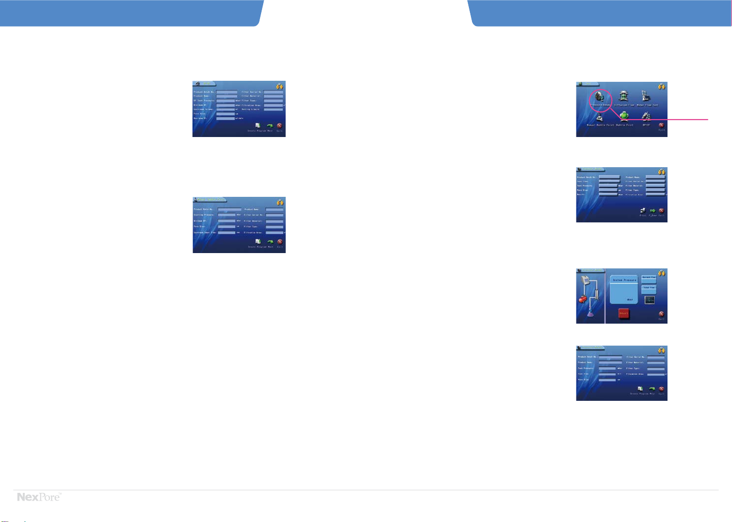
1. Select " Pressure Decay" in the "Test" interface
2. Input the parameters
3. After all test parameters are entered,click “Next”;
4. Click/Select “START” to start test after confirming that
the instrument's inlet and outlet air lines are properly
connected.
5. At the end of the test, the Interface displays the
Pressure Decay Test Results and Curves. To instantly
print these results, click/select “PRINT”.
6. Click/Select "EXIT" and the system automatically saves
the test results and returns to the parameter settings
page.
Enter the “PRESSURE VALUE” of the dwell test
corresponding to the filter in the Hold Pressure
text box.
Click to enter the test and enter “PRODUCTION
LOT NUMBER”, “PRODUCT NUMBER” and
“FILTER SERIAL NUMBER”
4.2.4.4 Pressure Decay Test
Click/Select to enter
the Pressure Decay
Test
Enter “FILTER SPECIFICATIONS”, “APERTURE”,
and “FILTER AREA”
Click/Select “START” to start test
CF 7.2IntegrityTester Instruction ManualCF 7.2IntegrityTester Instruction Manual
- 12 - - 13 - Bubble Point Test
It simplifies the operation and reduces the testing time to
test diffusion flow and bubble point simultaneously.
1. Select "BP+DF" on the "Test" interface;
2. After entering the test parameters, click "Next" to start.
4.2.4.3 Manual Bubble Point Test
The manual bubble point function can be used as a gas
source for manual test of the filter element, and the
operator needs to observe the bubble generation
downstream of the filter element in the meantime.
1. Select "Manual Bubble Point" on the "Test" interface;
2. After entering the test parameters, click "Next" to start;

Diffusion Flow Test Procedure
- 14 - - 15 -
CF 7.2IntegrityTester Instruction ManualCF 7.2IntegrityTester Instruction Manual
1. Click/Select “DIFFUSION FLOW” in the “TEST”
selection inferface.
2. Click/Select “DIFFUSION FLOW”- (MICROFIL-
TRATION)” and follow the prompt to enter the
filter specifications. If the user does not know
"MAXIMUM DIFFUSION FLOW" or "UPSTREAM
VOLUME", click/select "OK" to start the
measurement. The default standard for the
maximum diffusion flow is the value in the
parameter settings and upstream volume is
automatically calculated
3. After the test parameters are entered, click/
select “NEXT” to enter the diffusion flow test
interface to start the test. View the curve in real
time with the bubble point.
4. At the end of the test, the Interface displays the
Test Results and Curves. To instantly print these
results, click/select “PRINT”.
5. Click/Select "EXIT" and the system automatically
saves the test results and returns to the parameter
settings page.
4.2.4.5 Diffusion Flow Test (microfiltration)
Click/Select to enter
Diffusion Flow Test
Click/Select "ULTRA-FILTRATION" in the test
category.
As above if the user does not know
"MAXIMUM DIFFUSION FLOW" or
"UPSTREAM VOLUME", click/select "OK" to
start the measurement.
Pressure Decay Test
Diffusion Flow - (ultra-filtration) Test Procedure is
the same as described above for Diffusion Flow -
(microfiltration).
4.2.4.6 Diffusion Flow Test (ultra-filtration)
Click/Select "DIFFUSION FLOW -
(ULTRA-FILTRATION)”
1. Click/Select “Test” in the “Main Menu”.
Click “Traffic Detection” in the system operation
selection interface to enter the “Traffic Detection”
interface.
2. Click/Select “Water Flow” and enter “Product batch
No.”, “Product name ” and “Filter Serial No.”. If the
user does not know "MAXIMUM FLOW", click/select
"Next" to start the measurement. The default
standard for the maximum diffusion flow is the
value in the parameter settings
3. View the curve in real time with Bubble Point
4. At the end of the test, the Interface displays the Test
Results and Curves. To instantly print these results,
click/select “PRINT”.
5. Click/Select "EXIT" and the system automatically
saves the test results and returns to the parameter
settings page.
If the user does not know the "MAXIMUM
FLOW", click/select "Next" to start the
measurement.
4.2.4.7 Water Flow Test
Click/Select to enter the
Water Instrusion Test.
Water
Upstream Valve
Closed Outlet
Gas
In
Out
CF 7.2IntegrityTester

Flow Test Supplement
1. If the upstream volume is entered during the Diffusion Test, the instrument will skip the
upstream volume test procedure.
2. The filter element used for diffusion flow testing can only be done once
3. As with bubble if the filter area is unknown the system defaults are 0.6m²for a 10inch
single core filter, and 0.04m²for a capsule filter
4. Water flow Test must be refilled with water before the second test
5. When performing the Water Flow Test, please input pressure according to the instructions
to avoid damage to the filter element
6. When testing for water flow, keep the instrument above the filter cartridge and connect the
tubing to the top of the filter cartridge to prevent back suction
7. The molecular cut-off weight for ultra-filtration parameters only calibrates filter
specification and is not a test results
5. Touchscreem
6. User Management
7. Audit Trail
8. About
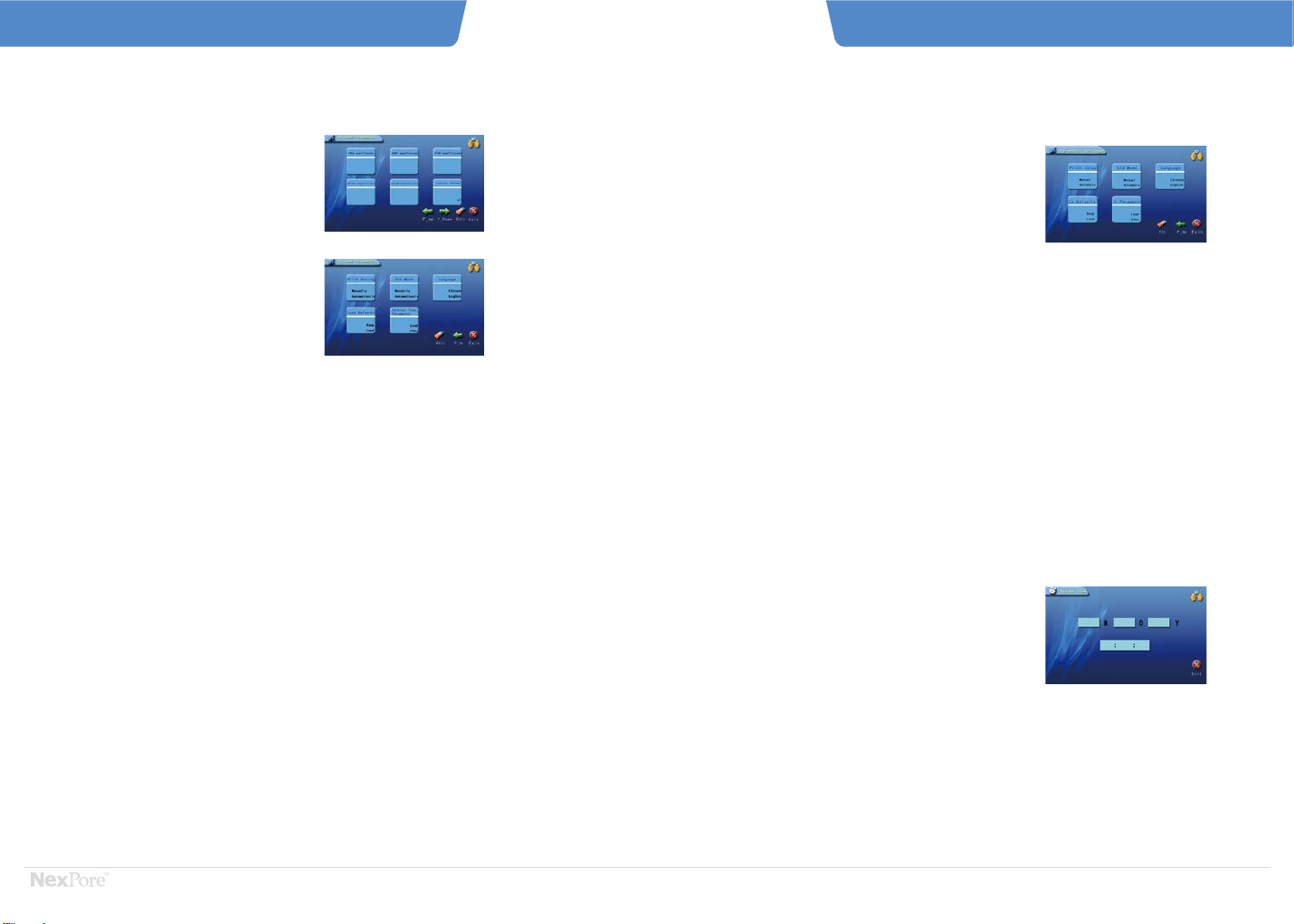
System parameter are further subdivided into two sections:
browsing and editing.
Click/Select “PARAMETER SETTINGS” to enter browse. In
this section, you can check the current system user name,
test pressure increase, default maximum diffusion flow, and
maximum flow and pressure of the hydrophobic filter PTFE.
When "Edit" is clicked / selected and if the user level is
appropriate, then you enter “EDIT” interface. After setting
each parameter, click/select “SAVE” to return to the previous
page (Browse)
For Hydrophobic PTFE: view current system
user name, test pressure increase, default
maximum diffusion flow, and maximum flow
and air pressure.
For advanced user level, click/select ‘Edit’ to
enter the parameter setting edit status.
5. System Configuration
5.1 System Parameter
CF7.2 Parameters
1. System Parameter
2. Date/Time
3. Communication Setting
4. Battery
Diffusion Flow Test Procedure
- 16 - - 17 -
CF 7.2IntegrityTester Instruction ManualCF 7.2IntegrityTester Instruction Manual
Water Flow Test
- 18 - - 19 -
CF 7.2IntegrityTester Instruction ManualCF 7.2IntegrityTester Instruction Manual
System Parameter Settings
Maximum Diffusion Flow:
The maximum diffusion flow value allowed by the filter
element in the corresponding diffusion flow measurement
pressure. It is necessary to set the maximum diffusion flow
of the four filter elements: 10-inch asymmetric membrane
filter (PES), 10-inch symmetric membrane filter (PVDF,
Nylon), and 10-inch air filter (PTFE).
Maximum Flow Rate:
The maximum flow rate of the aqueous solution immersed in
the filter at the specified test pressure and unit time during
the water flow test. It is necessary to set the maximum flow
of the 10-inch PTFE filter.
Air Source Pressure: recommended to be set at 1000 mbar
less than the actual air source.
Coefficient:
PES / PVDF / CN-CA / PTFE / NYLON coefficients should
retain factory settings
Internal Volume / External Tank : Capacity should retain
factory settings
Pressure Increase: refers to the amount of gas in one
intake. The larger the value, the larger the amount of
intake air, the faster the test speed, but the lower the
accuracy. This value can be set according to customer
specifications/needs.
If the test time exceeds 25 minutes, causing the
instrument to report an error, it is recommended to
increase the pressure increase.
Examples :
a. maximum diffusion flow of a 10-inch PES filter is
30.0 ml/min
b. maximum flow rate of the 10-inch PTFE filter is
0.75 ml/min when using the water flow test.
Flow Test Supplement
For advanced user level, click/select ‘ALT’ to
enter the parameter setting edit status.
“MANUAL” the user must manually click/select “PRINT”
to print test results after the test is completed. “AUTO”
the test results will automatically print
Click/Select "Date / Time" to enter the "Date / Time"
interface, as shown
For advanced user level, click/select “EDIT” to enter “EDIT
PARAMETER SETTINGS”.
Supplement:
In order to ensure correct and reliable measurement results,
a user password needs to be setup, and only relevant
personnel can change these measurement parameters.
Each machine has a factory default password. To facilitate
production management, the password can be changed in
the user management interface.
Printing Settings
To reduce user's test time in production and extend the
service life of the filter element, the instrument provides
two options after the bubble point is tested. Option 1: to
ask the user whether to continue the operation, if the user
clicks/selects "OK" the actual bubble point will always be
tested. If the user clicks/selects “CANCEL” the test will
end and results provided. Option 2: terminate the test
directly and get the test results. Users can select either
option based on their specific requirements/needs
Load Default/Initial Test Parameters:
The system's default parameters include test
pressure increase, default maximum diffusion
flow, air supply pressure, and test parameters
loaded or reverted to factory settings.
Use this feature with caution.
Interchanging between Chinese and English still
under development
End Mode Language Selection
5.2 Date / Time
Click/Select "PROJECT" and then click/select
"ALT".
Click/Select "ADD" and follow the prompts to
add users and passwords.
Click/Select "SAVE"
In the system settings interface, click/select "USER
MANAGEMENT" to enter the user management
interface.
In the system settings interface, click/select "AUDIT
TRAIL" to enter “AUDIT TRAIL”. Users can browse
historical records.
To modify or delete, first select the item, then
click/select “EDIT” to change the user name or user
password or click/select "DELETE" to delete the
user.
Users cannot modify or delete user that are either
higher than them or at the same level than them in
the hierarchy management.
Click/Select "ADD" and follow the prompts to add a
user and create username/password/save.
Currently CF7.2 Integrity Tester supports 4 levels
of user.
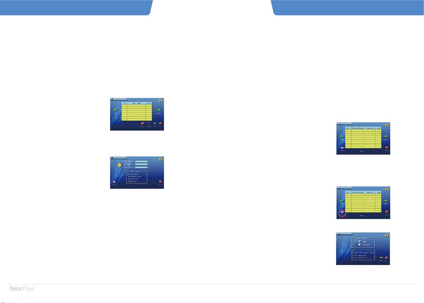
5.6 User Management
5.7 Audit Trail
“COMMUNICATION SETTINGS” is mainly used to
communicate with the host computer. CF 7.2 Integrity Tester automatically saves the last
12,000 test data records (including test curves and
complete test conditions). At this point, the earliest
test data is automatically overwritten.
Historical records include: Bubble Point, Manual Bubble
Point, BP+DF, Pressure Decay, Diffusion Flow, and water
flow Test Results.
When CF 7.2 Normal Test is finished, the test result
interface will pop up. At this time, after pressing “EXIT”,
the system automatically saves the data.
History is stored in the recording unit inside the
instrument according to production lot number.
The history query is also based on the production
lot number. The history interface is shown below:
To ensure the safety and integrity of the
history, the CF 7.2 Integrity Tester can export
the historical data via USB, SD card and data
port and be saved separately.
“POWER MANAGEMENT” is mainly used when the
instrument works in different power supply
environments. For some parameters of the
instrument power mode, including battery power,
the instrument will automatically reduce power
consumption.
Temporarily unavailable
In the Instrument Standby Interface, click/select “Test
Results” to enter “Test Results” interface.
Click/Select “EXPORT” and “EXPORT MEDIA” interface
will be displayed.
Select the media to export data, and determine whether to
clear the history.
After confirming the error, click/select “OK” to export the
data.
Please export and then delete data if you so choose.
The exported format is a .dat file, which can be opened by
using the matching PC software.
When exiting, click/select “EXIT” continuously to return to
“SYSTEM OPERATION SELECTION INTERFACE.”
6. Test Results
- 20 - - 21 -
Please export and then delete data if you so choose.
Click/Select "EXPORT" and select the appropriate
export data media to export.
Record Saving View History
Test Results Exporting Process
5.3 Communication Settings 5.4 Power Management
5.5 Touch Management
System Parameter Settings
CF 7.2IntegrityTester Instruction ManualCF 7.2IntegrityTester Instruction Manual
User Management

The system supports two print modes.
1. Click/select "PRINT" to instantly print the current test results whenever this interface appears
2. In “Test Results”, click/select the Test Option and then click/select “PRINT”.
There will be a lag between clicking/selecting print and the results printing.
CF 7.2 Integrity Tester has a built-in printer and the following sections describe how to replace the paper
and ribbon.
7. Data Printing
1. Important Notice - paper specifications are: outer
diameter 20mm, inner diameter 11mm, paper width 47mm
2. Turn on the power switch
3. Press the elastic plastic on both ends of the printer panel
toward the center and pull up to open the printer panel.
4. Pull the plastic plate at the upper end of the card slot
outward, and then rotate the center roller in the card slot
to the center line in a vertical state, and pull out the empty
paper roll.
5. Insert the center roller into the new paper roll and reinstall
the card slot. Note that the installed paper slot should be
below the card slot.
6. Pull the paper out and place it in the first slot on the card
slot, and open the paper feed button (green cylindrical at
the bottom right of the paper card slot) and feed the
paper until the paper exits.
7. Close the printer panel.
1. Open the printer panel as described in the above
8.1 section
2. Pull the plastic assembly on the top of the printer out.
3. Hold the ribbon on both sides and pull it up.
4. Pass the new ribbon through the printer, snap the
holes in the ribbon to the gears on the printer,
press the flat ribbon, and then flatten the ribbon
inward.
5. Flatten the plastic components inward and close
the printer panel.
8. Printer Installation and Maintenance
- 22 - - 23 -
8.1 Installing/Replacing Paper 8.2 Installing/Replacing Ribbons
CF 7.2IntegrityTester Instruction ManualCF 7.2IntegrityTester Instruction Manual
History Record Data Printing
If the working fuse is damaged, it can be replaced with
a spare fuse. The replacement steps are as follows:
1. Unplug the power cord
2. In the middle of the switch and socket, find the cover
with the fuse pattern and use a flat-blade screwdriver
to pry open the cover
3. Pull out the working fuse in the card slot and load it
with the spare fuse in the cylinder
4. Reload the entire card slot into its original position
Due to GMP regulations, NexPore advises customers
to calibrate the tester once a year.
10. Instrument Calibration
9. Replacing the Main Fuse

During instrument use, there may be issues/problems with the CF 7.2 Integrity Tester. If the following problems
occur, please solve per the methods described below. If the problems/issues cannot be solved by the methods
below, please contact your NexPore Sales Engineer immediately.
Printer cannot print the test
results
Qualified filter elements are
determined by other means,
but cannot pass when tested
with CF7.2 Integrity Tester
a. test environment is below
0°C
b. out of paper
c. paper is not in place
d. incidental failure
a. The test environment temperature should be
between 0°C to 40°C; test must be performed
in a location with this range of temperature
b. Check to see if the printer is out of paper and if
it is replace per the Instructions illustrated in
this Manual
c. For other issues, shutdown and restart the
system but wait at least 5 seconds before
restarting.
a. Filter is not thoroughly
immersed
b. System leak
c. Tested filter temperature is
too high
d. Immersion liquid is
unreasonable
a. Thoroughly immerse the filter element to be
tested
b. Remover the filter and perform system self-test
c. As previously explained, Integrity Testing should
be performed at room temperature. When the
filter element temperature is too high, the
integrity test should be performed after the filter
element has naturally cooled.
d. Different filter materials need different immersion
liquids. Immersion liquid should be selected
according to factory report provided by the filter
manufacturer.
11. Common Problems
- 24 - - 25 -
CF 7.2IntegrityTester Instruction ManualCF 7.2IntegrityTester Instruction Manual
Common Problems
Problem Causes Solutions to Problem
1 .
2 .
Pre-pressurization failure
during testing
a. Filter is not thoroughly
immersed
b. System leak
c. The instrument fills with
liquid
a. Thoroughly immerse the filter element to be
tested
b. Remover the filter and perform system
self-test
c. Check to see if there is any liquid outflow in
the exhaust port during testing. If there is,
please return the CF7.2 to the factory for
repairs.
3 .
Screen drifts/shifts Click/Select “LOGIN INTERFACE” until the
“VERIFICATION PAGE” appears. Click/Select
“+” on the page with the touch pen until
verification is over.
4 .
Diffusion Flow and Water
Flow Values are too large
a. In parameters initialization,
the buffer tank volume does
not match the actual buffer
tank
b. The internal pipeline has a
leak and the upstream
volume is calculated as too
large
c. Influent, resulting in a buffer
tank volume smaller than the
set buffer tank volume
d. No instrument issues but
there are leaks in the external
pipeline
e. The instrument needs to be
verified.
a. Check that the parameters are correct
b. Have the instrument check to see if the filter
is in the liquid
c. Have the instrument check for leaks.
d. Performa self-test with a filter to detect
whether there is a leak in the external
pipeline
e. Calibrate the instrument and observation
coefficient.
7 .
Outlet quick connector and
unable to plug in the air inlet
connector
Outlet corrosion place the outlet quick connect in alcohol8 .
a. The air source pressure
setting of the internal
parameters of the instrument
is too low
b. The source pressure is lower
than the bubble point value
c. The instrument or filter has
a leak
d. Sensor failure
a. Check that the parameters are correct
b. Verify that the gas source is up to standard
c. Check if there is a leak in the tester or
external equipment
d. Sensor Verification.
9 .
A small amount of liquid
discharges
place the CF7.2 in an upright position with the
outlet facing up. Perform a self-test. As the
self-test ends, the moisture in the chamber will
be discharged with the gas.
10.
The printer won’t release
the paper
Open the flip cover of the printer and with a
screwdriver slightly loosen the left and right
screws.
5 .
The start screen is either
a blue screen, flower
screen or black screen
Check that the power supply and screen
connection are normal and then place the
CF7.2 in a dry and ventilated environment for
a short period of time. If it has not been
released, contact the factory for repair.
6 .
Problem Causes Solutions to Problem

™
Global
Headquarters,
Netherlands
R&D,
Lab,
Facility,
Marketing,
Sales
Taiwan Headquarters
Lab, Facility, Marketing, Sales
World Wide Offices, California, Singapore, Korea, Japan, Hangzhou
Lab,
Marketing,
Sales
Manufacturing Site, Ireland
Facility, Lab, Sales
Contact Information
Vrijheidweg 57, 1526 RS, Wormerveer
Amsterdam, Netherlands
Tel: +31 75 2014000
Fax: +31 75 2014020
Web: www.nexpore.com
Email: [email protected]
Planing
Germany Office
Switzerland Office
Table of contents
Other Integrity Test Equipment manuals

Popular Test Equipment manuals by other brands


Elenco Electronics
Elenco Electronics S-3000 user guide

Agilent Technologies
Agilent Technologies 100 Operator's manual

Megger
Megger EZ-ThumpV3 user manual

WT
WT PH 2066UK Installation operation & maintenance

Keysight Technologies
Keysight Technologies U3022AM06 User's and service guide

Keithley
Keithley System SourceMeter 2602B quick start guide


