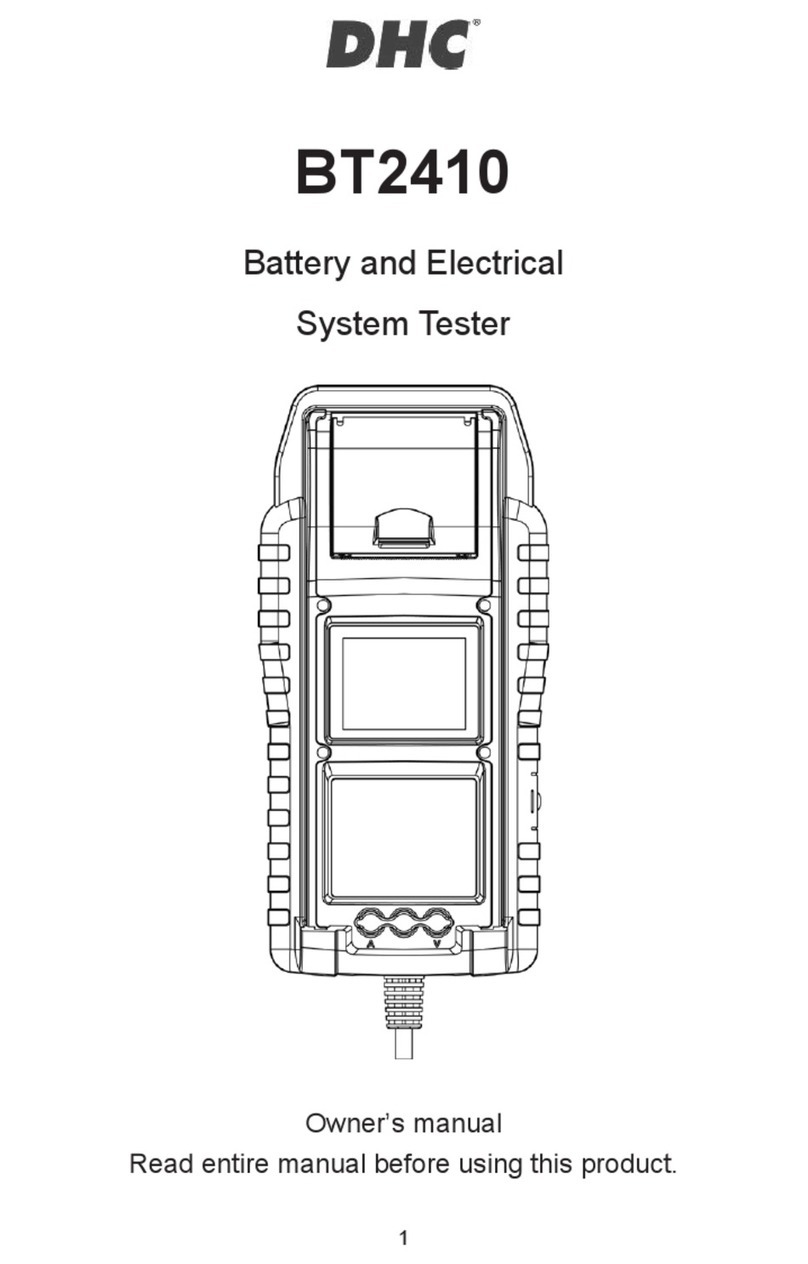
DHC BT2400 User manual

Model BT2400
BATTERY AND ELECTRICAL
SYSTEM TESTER
Owner’s manual
Read entire manual before using this product.

2
MAIN FEATURES
1. 6V & 12V starter battery test (including start-stop batteries)
2. 12V & 24V chanking & charging system test
3. USB port for future upgrade
4. Precise temperature compensation
5. Print out test results
6. Optional Amp clamp & Voltage probe.
IMPORTANT
Suggested operation range 0濎(32ʲ) to 50濎(122ʲ) in ambient
temperature.
WARNING
WARNING: This product can expose you to chemicals including arsenic, which is
known to the State of California to cause cancer.
For more information, go to www.P65Warnings.ca.gov.
1. Working in the vicinity of a lead acid battery is dangerous. Batteries
generate explosive gases during normal battery operation. For this reason,
it is of utmost importance, if you have any doubt, that each time before
using your tester, you read these instructions very carefully.
2. To reduce risk of battery explosion, follow these instructions and those
published by the battery manufacturer and manufacturer of any equipment
you intend to use in the vicinity of the battery. Observe cautionary markings
on these items.
3. Do not expose the tester to rain or snow.
English

3
PERSONAL SAFETY PRECAUTIONS:
1. Someone should be within range of your voice or close enough to come to
your aid when you work near a lead acid battery.
2. Have plenty of fresh water and soap nearby in case battery acid contacts
skin, clothing or eyes.
3. Wear safety glasses and protective clothing.
4. If battery acid contacts skin or clothing, wash immediately with soap and
water. If acid enters eye, immediately flood eye with running cold water for
at least ten minutes and get medical attention immediately.
5. NEVER smoke or allow a spark or flame in vicinity of battery or engine.
6. Be extra cautious to reduce risk of dropping a metal tool onto the battery. It
could spark or short-circuit the battery or other electrical parts and could
cause an explosion.
7. Remove personal metal items such as rings, bracelets, necklaces and
watches when working with a lead acid battery. It can produce a short
circuit current high enough to weld a ring or the like to metal causing a
severe burn.
PREPARING TO TEST:
1. Be sure area around battery is well ventilated while battery is being tested.
2. Clean battery terminals. Be careful to keep corrosion from contacting with
eyes.
3. Inspect the battery for cracked or broken case or cover. If battery is
damaged, do not use tester.
4. If the battery is not sealed maintenance free, add distilled water in each
cell until battery acid reaches level specified by the manufacturer. This
helps purge excessive gas from cells. Do not overfill.
5. If it is necessary to remove battery from vehicle to test, always remove
ground terminal from battery first. Make sure all accessories in the vehicle
are off to ensure you do not cause any arcing.
English

4
OPERATION & USE:
Note: Each time you connect the tester to a battery, the tester will run a quick
cable verification to ensure a proper connection through the output cables to
sensors in the clamp jaws. If the connection checks out OK, the tester will
proceed to the Home Screen. If the connection is poor, the display will show
“CHECK CABLE”. In this case, check cable connections for visible signs of
damage, as you may need to re-connect the clamps to the battery or replace the
cable end.
PAPER REPLACEMENT
1. Open the paper roll cover.
2. Place a new paper roll in the compartment. Make sure the thermal side is
upside placed as below.
3. Pull a short length of paper from the compartment and press down the
cover to close.
English

5
Precautions for using the integrated printer:
To prevent from overheating the integrated printer, it is not recommended to
constantly and repeatedly printing the same test result.
The printer should be rested for at least 1 minute if the print has been working for
2 minutes constantly.
Please avoid extremely operating the printer by constantly and repeatedly printing
the same test result.
According to general usage scenarios, it takes about 10~20 seconds to print out a
single result based on the type of the test that is performed.
And the next test is usually completed 20~30 seconds later or more after printing
the previous result.
In this case, the printer will always be cooled down enough and ready for printing
the result of the second test.
If the integrated printer does start to get warm, please have it rested for a while
and cooled down before using the printing function again.
English

6
HOW TO REPLACE CABLE END:
1. Detach the clamp lead when the replacement is necessary.
2. Make sure the new clamp lead is well connected.
*NOTE that do not detach the cables unless necessary to make sure the pins are
not rusted or corroded by the acid liquid.
INSTALL / REPLACE THE INTERNAL BATTERIES.
The BT2400 offers two difference options for its internal batteries.
A. 6pcs AA alkaline batteries.
B. 2pcs 18650 rechargable lithium batteries.
IMPORTANT:
It is recommended that the user to apply protected type 18650 lithium
batteries instead of unprotected type 18650 batteries.
Because the circuit of the protected type 18650 battery is embedded in the
cell packaging (battery casing) which protects the cell from “over charge”,
heat or “over discharge”, over current and short circuit and less likely to
overheat, burst or start on fire.
English

7
Replace / Install the AA alkaline batteries.
1. Unscrew the battery cover to
access the battery tank.
2. Pull the strap up to remove the AA
batteries and install new ones
(Always keep the strap under the
batteries.)
3. Close the battery cover and tighten the screw.
Replace / Install the rechargable 18650 lithium batteries.
1. Unscrew the battery cover to access the battery tank.
2. Install / Replace the 18650 lithium
batteries from the battery holder.
3. Plug in the connector of the 18650
lithium battery holder.
4. Place the 18650 lithium battery
holder in position. (Always keep the
strap under the battery holder.)
5. Close the battery cover and tighten
the screw. (Make sure the battery
cover doesn’t clip on the cables of
the battery holder when closing.)
6. Tighten the srew of the battery
cover.
*18650 lithium batteries are not
included in the package.
English

8
Vehicle Identification Number (VIN)
VIN JJ01806
BATTERY TYPE VRLA/GEL
RATING CCA/SAE
CAPACITY 500
BATTERY IN VEHICLE NO
SETUP START
Battery
Tes
t
System
Test
IR
Test
V/A
Meter
s
Setting
History
6V & 12V BATTERY TEST:
1. Select BATTERY TEST from the
main menu
2. Enter VIN number
a) Press ENTER when
the cursor is at the
input area to initiate
the virtual keyboard.
3. Select SETUP to change the battery setting.
(The user could click “START”if the battery setting is the same as the
previous test.)
4. Select Battery type
Available types: VRLA/GEL, FLOODED, AGM-FLAT, AGM SPIRAL, EFB.
5. Select Rating:
Available ratings: CCA/SAE, DIN, EN, EN2, IEC, JIS, CA/MCA
English
b) To clear the input area, select "X" and press ENTER.
c) To skip VIN input, select "NEXT" and press ENTER.

9
Aim the te
mperature
sensor to the bat
tery.
Proceed In vehicle Test?
YES / NO
6. Select Capacity
Available capacity range:
25~3000 CCA/SAE
25~3300 EN
25~2830 EN2
25~1985 IEC
JIS (By Battery Type)
25~1685 DIN
25~3600 CA/MCA
7. Check if the battery is tested in a vehicle or not. (Select Yes/No)
8. After setup, the BT2400 will
ask the user to point its
temperature sensor at the
battery, press ENTER to
confirm temperature reading
and continue.
9. BT2400 will then check if the
user would like to proceed an
In-Vehicle Test,
If yes, the BT2400 will
automatically proceed to the
system test after the battery
test is completed. If no, the
BT2400 will perform only the
battery test.
10. Start Testing:
The BT2400 will automatically perform a battery test or In-Vehicle Test
after item 7 has been checked.
Use the dircetionl keys to review the test result. Or move the cursor to the
printer icon to print out the result.
English

10
<<SURFACE CHARGE>>
*Note that if the BT2400 detects the surface charge. The BT2400 will pop up a
notification to ask the user to turn on loads / headlights for 15 seconds to
eliminate the surface charge.
If the BT2400 keeps popping up the notification of “Turn on loads & headlights for
15seconds”, it might because of the vehicle is equipped with the latest LED
headlights & modern vehicle control modules. Turn on loads & headlights for 15
seconds on these vehicles might not be enough to eliminate the surface charge.
Please select “NO”to the “Battery Test In Vehicle Setting”to skip the surface
charge detection and carry on the test. (Refer to 6V & 12V Battery test item 7.)
BATTERY TEST RESULTS
1. GOOD & PASS
The battery is good and capable of holding a charge.
2. GOOD & RECHARGE
The battery is good but needs to be recharged.
3. CAUTION
The battery may be serviced but decrease the capability of starting the
engine gradually. The battery may fail under extreme climate conditions.
There may be a poor connection between the vehicle and the battery
affect the charging function. Please pay attention to the battery for
replacement consideration and charging system checking.
4. RECHARGE & RETEST
Battery is discharged, the battery condition cannot be determined until it
is fully charged. Recharge & retest the battery
5. BAD & REPLACE
The battery will not hold a charge. It should be replaced immediately.
6. BAD CELL & REPLACE
The battery has at least one cell short circuit. It should be replaced
immediately
7. LOAD ERROR
The tested battery is bigger than 3000CCA/SAE or the clamps are not
connected properly. Please fully charge the battery and retest after
excluding both previous reasons. If reading is the same, the battery
should be replaced immediately.
English

11
Battery
Test
System
Test
IR
Test
V/A
M
eters
Setting
History
System
Tes
t
Cranking Test
Turn off loads
Start engine
System
Tes
t
Cranking Result
N
ormal
Cranking Voltage
1
0.78V
Lowest Voltage
9.09V
System
Te
st
Cranking Result
<<NEXT>>
System
Test
Is it a diesel engine
?
YES / NO
12V & 24V SYSTEM TEST:
1. Select “SYSTEM TEST”from the main menu.
2. Enter or scan the VIN of the vehicle.
*The VIN input method is the same as VIN input of the battery test.
3. Turn off loads and start engine.
4. Use directional keys to review cranking test result.
5. Select NEXT to proceed to charging test.
6. Check “Is it a diesel engine?”by selecting YES / NO.
*If YES, the BT2400 will ask
the user to rev the engine for
40 seconds before proceeding
to idle & load on test.
*If NO, the BT2400 will
proceed with the idle & load on
test directly.
English

12
System
T
est
Alt. Idle
Test
Mke sur
e all
loads are
off
<<NEXT>>
System
T
est
Alt. Idle Test
N
ormal
Idle Voltage
1
3.87V
<<NEXT>>
System
T
est
Ripple Test
T
urn on loads.
<<NEXT>>
System
T
est
Rev the engine up
to 2,500rpm for
15 seconds.
System
T
est
Ripple Test
Normal
Ripple Voltage
0.12V
<<NEXT>>
System
T
est
Alt. Load Test
Nor
mal
Load Voltage
1
3.93V
<<NEXT>>
7. Select NEXT when idle test is completed and move on to the ripple & load
on test.
8. Turn on loads and rev engine for 15 seconds.
(The BT2400 will countdown 15 seconds)
9. Once completed, the ripple & load test results are displayed.
English

13
Test
Report
Cranking Test
Normal
Cranking Voltage
10.78V
Lowest Voltage
9.09V
Test
Report
Cranking Test
Test
Report
Alt. Test
Idle Normal
Voltage 13.87V
Load Normal
Voltage 13.93V
<PRINT> <DONE>
Test
Report
Ripple Test
Norm
al
Ripple Voltage
0.12
V
<PRINT> <DONE>
10. Select NEXT to review the complete system test results including the
cranking, idle, ripple, & load on test results.
11. Use directional keys to switch between 4 different pages of the system test
results.
12. Select PRINT if you would like to print out the system test result.
CRANKING TEST RESULTS:
1. CRANKING VOLTS NORMAL
The system is showing normal draw. Press «ENTER» to perform the
charging system test.
2. CRANKING VOLTS LOW
The cranking voltage is below normal limits, troubleshoot the starter with
manufacturers recommended procedure.
3. CRANKING VOLTS NOT DETECTED
The cranking voltage is not detected.
English

14
IDLE TEST RESULTS:
1. HIGH CHARGING VOLTS WHEN TESTING AT IDLE
The voltage output from the alternator to the battery exceeds the normal
limits of a functioning regulator. Check to ensure there is no loose
connection and the ground connection is normal
If there is no connection issue, replace the regulator. Since most
alternators have the regulator built-in, this will require you to replace the
alternator. The normal high limit of a typical automotive regulator is 14.7
volts +/- 0.05. Check manufacturer specifications for the correct limit, as it
will vary by vehicle type and manufacturer.
2. CHARGING SYSTEM NORMAL WHEN TESTING AT IDLE
The system is showing normal output from the alternator. No problem is
detected.
3. LOW CHARGING VOLTS WHEN TESTING AT IDLE
The alternator is not providing sufficient current to the battery. Check the
belts to ensure the alternator is rotating with engine running.
If the belts are slipping or broken, replace the belts and retest. Check the
connections from the alternator to the battery. If the connection is loose or
heavily corroded, clean or replace the cable and retest. If the belts and
connections are in good condition, replace the alternator.
RIPPLE TEST RESULTS:
1. RIPPLE DETECTED NORMAL
Diodes function well in the alternator / starter.
2. NO RIPPLE DETECTED
Ripple is not detected.
3. EXCESS RIPPLE DETECTED
One or more diodes in the alternator are not functioning or there is stator
damage. Check to ensure the alternator mounting is sturdy and that the
belts are in good shape and functioning properly. If the mounting and
belts are good, replace the alternator.
English

15
Battery
Test
System
Test
IR
Test
V/A
M
eters
Setting
History
IR
T
est
Directly connect to the
battery
<<NEXT>>
LOAD ON TEST RESULTS:
1. CHARGING SYSTEM HIGH WHEN LOAD ON TESTING
The voltage output from the alternator to the battery exceeds the normal
limits of a functioning regulator.
Check to ensure there are no loose connections and that the ground
connection is normal. If there are no connection issues, replace the
regulator. Since most alternators have the regulator built-in, this will
require you to replace the alternator.
2. CHARGING SYSTEM LOW WHEN LOAD ON TESTING
The alternator is not providing sufficient current for the system’s
electrical loads and the charging current for the battery. Check the belts
to ensure the alternator is rotating with the engine running. If the belts
are slipping or broken, replace the belts and retest.
Check the connections from the alternator to the battery. If the
connection is loose or heavily corroded, clean or replace the cable and
retest. If the belts and connections are in good working condition,
replace the alternator.
3. CHARGING SYSTEM NORMAL WHEN LOAD ON TESTING
The system is showing normal output from the alternator. No problem
detected.
IR TEST:
1. Select IR TEST from the main menu.
2. Use the clamps to connect with the battery directly.
English

16
IR
Te
st
Test Report
Voltage
12.93V
IR
22.28mȟ
<PRINT> <DONE>
3. Measure the battery temperature by aiming the temperature sensor to the
battery
4. Once the IR test is completed,
the BT2400 will display the
voltage & internal resistance
value on the result page.
5. Select DONE to return to main
menu or select PRINT to print
out the IR test result.
AMP CLAMP & VOLT PROBE INSTRUCTION GUIDE
(DC/AC Current & DC Voltage measurement)
zOptional voltage probe烉MAX 40VDC (Base on the black clamp)
zOptional current clamp烉MAX 600A (1A/1mV)
Note: Please use only the AMP clamp & Volt probe provided by DHC Specialty
Corp.
English

17
Battery
Test
System
Test
IR
Test
V/A
M
eters
Setting
History
V/A
Meters
Voltmeter
--.--V
Ammeter
--- A
<<Record MAX>>
DC/AC Current measurement
1. Install the 9V battery.
2. Connect Clamp Meter to the jack A on BT2400
3. Press the button ZERO. Make sure the display reads zero.
4. Press the trigger to open the transformer jaws and clamp one electrical
wire.
5. Make sure the clamp jaw is perfectly closed.
6. Select V/A METERS from the main menu.
7. Read the displayed value.
8. select “Record Max”and then select “Stop Recording”, the BT2400 will
display the max current recorded durging the recoding period.
DC Voltage Measurements
*Do not test more than 60V, it may damage the tester.
1. Connect Red Test Lead to the jack V on BT2400
2. Use the test lead to touch a point within the network of the battery.
3. Select V/A METERS from the main menu.
4. Read the displayed value.
5. select “Record Max” and then select “Stop Recording”, the BT2400 will
display the max voltage recorded durging the recoding period.
English

18
Battery
Te
st
System
Test
IR
Test
V/A
M
eters
Setting
History
Back
-
light
Left Right
Lan
-
guage
1. ENGLISH
2. ITALIAN
3. DEUTSCH
4. ESPANOL
5. FRANCAIS
6. PORTUGUES
Setting
1. BACKLIGHT
2. LANGUAGE
3. DATE&TIME
4. INFORMATION
5. OTA UPGRADE
SETTINGS
Enter SETTING from the main menu and then select the item you would like to
adjust or proceed. Such as backlight, language, date & time, customized
information, and cable diagnosis. Or simply check the version of the BT2400.
BACKLIGHT
1. Select BACKLIGHT and use directional keys to adjust the brightness of
the display.
2. Press ENTER to confirm the
setting and return to setting
menu. Or press BACK key
to discard the change and
return to the setting menu.
LANGUAGE
1. Enter LANGUAGE to select the language desired.
2. Press ENTER to confirm the
setting and return to setting
menu. Or press BACK key
to discard the change and
return to the setting menu.
English

19
D
ate
&
Time
Date
Time
Info.
Printout NO
Edit
Erase information
Version
FW version
BT2400_WW_V00
.X
Serial number
20210101
0002
DATE & TIME
1. Select DATE & TIME to
adjust the time.
2. Use directional keys to
adjust and press ENTER to
proceed to the next item.
3. Once completed, press
BACK to return to the setting
menu.
INFORMATION
1. Enter INFORMATION to
enable / disable, edit or erase
the customized print out info.
2. Press BACK to return to the
setting menu.
VERISON
1. Select “VERSION”to check
the current firmware veriosn,
serial number of the BT2400.
English

20
Cable
D
iag-
nosis
Guide:
Clamp on a battery over
12.4V and make sure its
posts are clean.
Press ENTER to start.
<<START>>
Cable
D
iag-
nosis
Test Report
Positive:
G
OOD
Negative:
G
OOD
<<DONE>>
Histo
ry
Test Result
Test Counter
Test
R
esult
Battery Test
System Test
In Vehicle Test
Erase
Battery
Test
Today
2
One day ago
5
Two days ago
3
…….
CABLE DIAGNOSIS
1. Select “CABLE DIAGNOSIS”to perform self diagnosis of the cable set.
2. An instruction will be popped up on the screen.
1-1. Clamp on a battery that the voltage is above 12.4V. And make sure
its posts are clean.
1-2. Press ENTER to start
3. Select START to start the cable diagnosis and check the result.
HISTORY
HISTORY-TEST RESULT
1. Select “HISTORY”and then
enter “TEST RESULT”to
review the test results within
the last 7 days.
2. Select between test types &
days for reviewing
3. Select “ERASE” will clear all the test records that saved in BT2400.
English
Table of contents
Languages:
Other DHC Test Equipment manuals

