Intel res3tv360 Instructions for use

Intel® Integrated RAID Module
RMS3VC160
Hardware User Guide
A document providing an overview of product features, specification data, and
hardware installation instructions
Rev 1.0
May 2016
Intel Server Boards and Systems


Intel® Integrated RAID Module RMS3VC160 Hardware User Guide
i
Document Revision History
Date Published
Revision
Revision Change Description
May 2016
1.0
Initial release

Intel® Integrated RAID Module RMS3VC160 Hardware User Guide
ii
Disclaimers
No license (express or implied, by estoppel or otherwise) to any intellectual property rights is granted by this
document.
Intel disclaims all express and implied warranties, including without limitation, the implied warranties of
merchantability, fitness for a particular purpose, and non-infringement, as well as any warranty arising from
course of performance, course of dealing, or usage in trade.
This document contains information on products, services and/or processes in development. All information
provided here is subject to change without notice. Contact your Intel representative to obtain the User Guide.
The products and services described may contain defects or errors known as errata which may cause
deviations from published specifications. Current characterized errata are available on request.
Intel, the Intel logo, are trademarks of Intel Corporation in the U.S. and/or other countries.
*Other names and brands may be claimed as the property of others
© 2016 Intel Corporation

Intel® Integrated RAID Module RMS3VC160 Hardware User Guide
iii
Preface
This document provides an overview of product features, specification data, and hardware installation
instructions for the Intel® Integrated RAID Module RMS3VC160.
Document Organization
This document includes the following chapters and glossary:
•Chapter 1 – Product Overview – provides a product overview of the features set and support
specifications
•Chapter 2 – General Feature Overview
•Chapter 3 – Hardware Installation – provides the product installation instructions
•Chapter 4 –Safety and Regulatory
•Glossary of Terms
Reference Documents and Online Articles
The following documents are available for download and will be useful to setting up and using your Intel
RAID controller.
Document Title
Description
What to Do when Unable to Enter BIOs
Or Intel® RAID BIOS Console During
Boot for Intel® Server Boards
Article ID: 000059999- If the Intel or OEM logo screen displays during POST, the BIOS
entry or Intel® RAID BIOS console command prompts are not visible. To gain access to
these prompts, you need to disable the logo screen.
12 Gbps SAS or 6G SATA Data Transfer
Controller Support for Intel RAID
Controllers
Article ID# 000008025 - How and where the controller supports 12-Gbps SAS (6G
SATA) data transfers
TA-1085—4Kn and 512e Advanced
Format with Intel® RAID and Server
Boards
Advanced Format 4K Sector Drive
Support for Intel RAID Controllers
Article ID# 000006173 - TA-1085—4Kn and 512e Advanced Format with Intel® RAID
and Server Boards
Product Support Collaterals
In addition to this User Guide, Intel provides documentation, device driver updates, and utilities that may be
necessary and/or useful for operation and support of the product described herein. Additional product
support collaterals can be downloaded from the following Intel web sites:
For product documentation, go to the following Intel web site:
http://www.intel.com/support/go/RMS3VC160
For product device drives and other software utilities, go to the following Intel web site:
https://downloadcenter.intel.com/product/91066

Intel® Integrated RAID Module RMS3VC160 Hardware User Guide
iv
Table of Contents
1. Product Overview..............................................................................................................................1
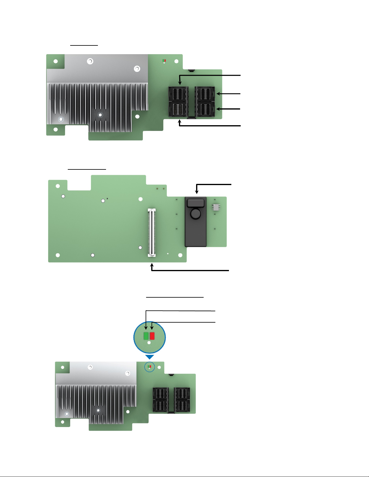
1.1 RAID Module Layout ..........................................................................................................................2
1.2 Feature Set............................................................................................................................................. 3
1.3 Performance Features .......................................................................................................................4
1.4 Device Support Limits .......................................................................................................................4
1.5 RAID Controller Specifications ......................................................................................................4
1.6 SAS/SATA Standards and Communication Protocols.........................................................5
1.7 Safety Characteristics........................................................................................................................ 5
1.8 Electrical Characteristics..................................................................................................................5
1.8.1 Operating and Nonoperating Conditions for the Intel® RAID Module ..........................5
2. General Feature Overview...............................................................................................................6
2.1 Benefits of the SAS Interface .........................................................................................................6
2.2 Summary of 12Gb/s Intel® RAID Controller Characteristics..............................................6
2.2.1 SAS Features.........................................................................................................................................6
2.2.2 SATA III Features.................................................................................................................................. 6
2.2.3 Usability Features................................................................................................................................ 6
2.2.4 Flexibility Features.............................................................................................................................. 7
2.3 Intel® 12 Gb/s SAS 3.0 Expander Support................................................................................8
2.3.1 SAS Expander Configuration..........................................................................................................8
2.4 RAID Module LEDs........................................................................................................................... 10
2.4.1 (LED1 – Red) RAID On Chip (ROC) Over Temperature LED............................................. 10
2.4.2 (LED2 – Green) RAID Module Heart Beat LED....................................................................... 10
3. Hardware Installation.................................................................................................................... 11
3.1 RAID Module Installation .............................................................................................................. 12
3.1.1 Requirements..................................................................................................................................... 12
3.1.2 Packing List......................................................................................................................................... 12
3.1.3 Installation Instructions................................................................................................................. 12
4. Safety and Regulatory (Class A) .................................................................................................. 14
4.1 Product Safety Compliance ......................................................................................................... 14
4.2 Product EMC Compliance – Class A Compliance................................................................ 14
4.3 Product Environmental Compliance........................................................................................ 14
Glossary ................................................................................................................................................... 16

Intel® Integrated RAID Module RMS3VC160 Hardware User Guide
v
List of Figures
Figure 1. Intel® Integrated RAID Module RMS3VC160 ...................................................................................1
Figure 2. Mezzanine Add-in Card Placement On Server Board..................................................................1
Figure 3. Supported Intel SAS Expander Options............................................................................................8
Figure 4 SAS Expander Support – RAID Controller SAS Port Identification.........................................8
Figure 5. Install the Barrel Standoff..................................................................................................................... 12
Figure 6. Figure 6 RAID Module Installation .................................................................................................... 13

Intel® Integrated RAID Module RMS3VC160 Hardware User Guide
vi
<This page is intentionally left blank.>

Intel® Integrated RAID Module RMS3VC160 Hardware User Guide
1
1. Product Overview
The Intel® Integrated RAID Module RMS3VC160 is a 16-port SAS/SATA mezzanine type RAID module
capable of supporting up to 240 SAS drives.
Figure 1. Intel® Integrated RAID Module RMS3VC160
As a mezzanine type add-in module, it is only compatible with Intel® Server Boards and Systems that include
an on-board high density 80-pin SAS module connector, as illustrated below.
Figure 2. Mezzanine Add-in Card Placement On Server Board

Intel® Integrated RAID Module RMS3VC160 Hardware User Guide
2
1.1 RAID Module Layout
Top Side
Snap-on Plastic Bumper
2x40-pin Server Board
Interface
Connector
P0 – Ports 0 - 3
P1 – Ports 4 - 7
P2 – Ports 8 - 11
P3 – Ports 12 - 15
Bottom Side
RAID Module LEDs
See section 2.4 for additional information
RAID Module Heart Beat
ROC Over Temperature

Intel® Integrated RAID Module RMS3VC160 Hardware User Guide
3
1.2 Feature Set
Feature
RMS3VC160
I/O Processor LSISAS3216 PCIe* to 12Gb/s SAS Controller
RAID Levels N/A
Cache Memory N/A
Form Factor Modular Mezzanine
Drive Interface Connectors 4 internal 4-port Mini-SAS HD SFF-8643 connectors
PCIe* Interface x8 PCI Express* 3.0. PCIe Performance uo to 8 GT/s per lane
Data Transfer Rates 12, 6, & 3 Gbps per port SAS and 6 & 3 Gbps per port SATA
Operating Temperature Maximum ambient: 65C
Operating System Microsoft Window*, Linux* (SuSE*, Red Hat*) Solaris* FreeBSD*
Drive Types 12G SAS, 6G SAS, 3G SAS, 6G SATA and 3G SATA
Maximum Physical Devices 1024
Management utilities
Yes
Standard Warranty 3 years, AWR options

Intel® Integrated RAID Module RMS3VC160 Hardware User Guide
4
1.3 Performance Features
Specification
RMS3VC160
PCI Express host data transfer rate 8GT/s per lane
Drive data transfer rate Up to 12Gb/s per lane SAS, up to 6GB/s per lane SATA
Maximum queue tags per drive As many as the drive can accept
Maximum number of concurrent
commands
5,376
1.4 Device Support Limits
Specification RMS3VC160
Maximum devices per controller
1024
Maximum enclosures
32 per port
1.5 RAID Controller Specifications
The following table lists the specifications for the Intel®Integrated RAID Module RMS3VC160
Specification
RMS3VC160
SAS controller and processor
Broadcom* SAS3216 ROC Controller
Operating voltage
+3.3 V, +12 V
Card size
Mezzanine port PCI Express card size (64.39 mm x 139.16 mm)
Array interface to the host
PCIe Rev. 3.0
PCI Express bus data transfer
rate
Up to 8GT/s per lane
x8 lane width
Serial port
4-pin RS232-compatible connector (for manufacturing use only)
SAS ports
4 internal 4-port Mini-SAS HD SFF8643 connectors
Size of flash ROM for firmware
16 MB

Intel® Integrated RAID Module RMS3VC160 Hardware User Guide
5
1.6 SAS/SATA Standards and Communication Protocols
The Intel® Integrated RAID Module RMS3VC160 supports the ANSI Serial Attached SCSI standard, version
3.0. In addition, the controller supports the SATA III protocol defined by the Serial ATA specification, version
3.0. Supporting both the SAS interface and the SATA interface, the SAS controller is a versatile controller that
provides the backbone of both server and high-end workstation environments.
Each port on your RAID controller supports SAS devices, SATA devices, or both, by using the following
protocols:
•SAS Serial SCSI Protocol (SSP), which enables communication with other SAS devices
•SATA, which enables communication with other SATA devices
•Serial Management Protocol (SMP), which communicates topology management information directly
with an attached SAS expander device
•Serial Tunneling Protocol (STP), which enables communication with SATA devices through an attached
expander
SAS technology brings a wealth of options and flexibility with the use of SAS devices and SATA devices
within the same storage infrastructure. However, SAS devices and SATA devices bring individual
characteristics that make each one a more suitable choice depending on the requirements of the given
operating environment and storage needs. The Intel® RMS3VC160 RAID Module provides the flexibility to
combine these two storage technologies on the same controller and within the same enclosure. However
combining SAS drives and SATA drives with the same virtual drive is not supported.
1.7 Safety Characteristics
All 12Gb/s Intel® RAID Controllers meet or exceed the requirements of UL flammability rating 94 V0. Each
bare board is also marked with the supplier name or trademark, type, and UL flammability rating.
1.8 Electrical Characteristics
1.8.1 Operating and Nonoperating Conditions for the Intel® RAID Module
Operating (thermal and atmospheric) limits are as follows:
•Relative humidity range is 20 percent to 80 percentnoncondensing.
•Airflow must be at least 200 linear feet per minute (LFPM) to avoid operating the SAS3216 processor
above the maximum ambient temperature.
•Temperature range: +10°C to +55°C without battery backup unit
•Temperature range: +10°C to +45°C with battery backup unit
Non-operating (such as storage and transit) limits are asfollows:
•Relative humidity range is 5 percent to 90 percent noncondensing.
•Temperature range: –40°C to +70°C without battery backup unit
•Temperature range: 0°C to +45°C with battery backup unit

Intel® Integrated RAID Module RMS3VC160 Hardware User Guide
6
2. General Feature Overview
2.1 Benefits of the SAS Interface
SAS is a serial, point-to-point, enterprise-level device interface that leverages the proven SCSI protocol set.
SAS is a convergence of the advantages ofSATA, SCSI, and Fibre Channel, and it is the mainstay of the
enterprise and high-end workstation storage markets.
The SAS interface uses the proven SCSI command set to ensure reliable data transfers, while providing the
connectivity and flexibility of point-to-point serial data transfers. The serial transmission of SCSI commands
eliminates clock-skew challenges. The SAS interface provides improved performance, simplified cabling,
smaller connectors, lower pin count, and lower power requirements when compared to the original parallel
SCSI.
SAS controllers leverage a common electrical and physical connection interface that is compatible with
Serial ATA (SATA) technology. The SAS protocols and the SATA III protocols use a common thin, 7-wire
connector. The SAS/SATA III connector and cable are easier to manipulate, allow connections to smaller
devices, and do not inhibit airflow. The point-to-point SATA III architecture eliminates inherent difficulties
created by the legacy ATA master-slave architecture, while maintaining compatibility with existing ATA
firmware.
2.2 Summary of 12Gb/s Intel® RAID Controller Characteristics
2.2.1 SAS Features
•Support for 12 Gb/s, 6Gb/s, and 3Gb/s SAS data transfers per PHY.
•Support for SMP to communicate topology-management information.
•Support for SSP to enable communication with other SAS devices.
•Support for STP to enable communication with SATA devices through an attached expander.
•Provide a serial, point-to-point, enterprise-level storage interface.
•Simplify cabling between devices.
•Provide a scalable interface that supports up to 1024 devices through the use of expanders.
•Supports wide ports that consist of two, four or eight PHYs.
•Supports narrow ports consisting of a single PHY.
•Transfer data by using SCSI information units.
2.2.2 SATA III Features
•Supports SATA III data transfers of 6Gb/s
•Supports STP data transfers of 6Gb/s.
•Provide a serial, point-to-point storage interface.
•Simplify cabling between devices.
•Eliminate the master-slave construction used in parallel ATA.
•Permit addressing of multiple SATA targets through an expander.
2.2.3 Usability Features
•Drive spin-up sequencing control
•Provide LED signaling to indicate HDD activity for all PHYs
•Support for the internal SAS Sideband signal SFF-8485 (SGPIO) interface

Intel® Integrated RAID Module RMS3VC160 Hardware User Guide
7
Note: LED signals indicate an error condition or drive activity. RAID controllers support different blink
patterns for these LEDs, depending on the user configuration and storage enclosure. For information about
the LED blink patterns, contact your storage enclosure manufacturer.
2.2.4 Flexibility Features
•Flash ROM interface, a nonvolatile static RAM (NVSRAM) interface
•Flexible programming interface to tune I/O performance
•Permit mixed connections to SAS targets or SATA III targets
•Leverage compatible connectors for SAS connections and SATA III connections
•Permit grouping of up to eight PHYs into a single SAS wide port
•Permit programming of the World Wide Name

Intel® Integrated RAID Module RMS3VC160 Hardware User Guide
8
2.3 Intel® 12 Gb/s SAS 3.0 Expander Support
For system configurations that require more than 16 physical drives, the Intel® Integrated RAID Module
RMS3VC160 has support for the following Intel® RAID Expanders:
Intel Product Code
Product Description
iPC – RES3FV288
Intel®SAS Expander RES3FV288
SAS 3.0 12 Gb/s expander
•Featuring 6Gbps data aggregation for 12Gbps data transfer with 6Gb/s devices
•Low Profile MD2 PCIe* add-in card form factor
•28 internal ports and 8 external ports
•Power from PCIe x1
•HD Mini-SAS 8643 Connectors
Kit includes: (1) SAS Expander card, (2) HD-HD 250mm Expander-to-RAID card cables, PCI
brackets for Low profile and Full height
iPC – RES3TV360
Intel® SAS Expander RES3TV360
SAS 3.0 12 Gb/s expander
•Featuring 6Gbps data aggregation for 12Gbps data transferwith 6Gb/s devices
•Internal mount mid-plane form factor
•36 internal ports supporting point-to-pont 12, 6, and 3 Gb/s data transfer rates
•RA 4-pin power connector
•HD Mini-SAS 8643 Connectors
Kit includes: (1) SAS expander card; (1) 130mm Power cable; (1 set) Expander-to-backplane
cables: (4) HD-HD 165mm, (1) HD-HD 300mm, (1) HD-HD 250mm; (3) Rubber Pads;
mounting screws
Figure 3. Supported Intel SAS Expander Options
2.3.1 SAS Expander Configuration
The SAS ports of the RAID Controller are divided into two separate domains:Domain 1 and Domain 2. When
cabling the RAID Controller to a SAS Expander, one or both 4-port connectors within a common domain can
be cabled to a single SAS Expander Card. Mixing SAS ports from different Domains to a single SAS
Expander card cannot be supported.
Figure 4 SAS Expander Support – RAID Controller SAS Port Identification
Domain 2
Domain 1
P0
P1
P2
P3

Intel® Integrated RAID Module RMS3VC160 Hardware User Guide
9
Supported Intel SAS Expanders include an array of multiport mini-SAS HD (8643) connectors. Some are
used as Output connectors to a backplane, while others are used as Input connectors from the RAID
Controller. The following diagrams identify the connector types for each supported SAS expander card.
Input Cable Configuration NOTES:
The SAS Expander cards identified above can support one or two Input SAS Port cables
When routing two Input SAS Port cables from the RAID Controller, they must be from the same SAS Domain
as illustrated on the previous page
Intel® SAS Expander RES3TV360
Intel® SAS Expander RES3FV288

Intel® Integrated RAID Module RMS3VC160 Hardware User Guide
10
2.4 RAID Module LEDs
The RAID module includes a bank of four LEDs as shown in the following illustration.
Figure 5. SAS Module LED Identification
2.4.1 (LED1 – Red) RAID On Chip (ROC) Over Temperature LED
LED State
LED State Descriptions
OFF
Status = OK
ON (Red)
•Thermal limit of ROC was reached
•FW Faulted and didn’t load
properly
•FW missing
2.4.2 (LED2 – Green) RAID Module Heart Beat LED
LED State
LED State Descriptions
OFF
RAID Module firmware is not running
Steady Flash (Green)
Firmware is OK and is operational
Irregular Flash (Green)
Firmware has faulted
(LED2) RAID Module Heart Beat
(LED1) ROC Over Temperature

Intel® Integrated RAID Module RMS3VC160 Hardware User Guide
11
3. Hardware Installation
Warnings
Heed safety instructions: Before working with your server product, whether you are using this guide or any
other resource as a reference, pay close attention to the safety instructions. You must adhere to the
assembly instructions in this guide to ensure and maintain compliance with existing product certifications
and approvals. Use only the described, regulated components specified in this guide. Use of other
products/components will void the UL listing and other regulatory approvals of the product and will most
likely result in noncompliance with product regulations in the region(s) in which the product is sold.
System power on/off: The power button DOES NOT turn off the system AC power. To remove power from
the system, you must unplug all AC power cords from the server system before you open the chassis, add, or
remove any components.
Hazardous conditions, devices and cables: Hazardous electrical conditions may be present on power,
telephone, and communication cables. Turn off the server and disconnect the power cord,
telecommunications systems, networks, and modems attached to the server before opening it. Otherwise,
personal injury or equipment damage can result.
Installing or removing jumpers: A jumper is a small plastic encased conductor that slips over two jumper
pins. Some jumpers have a small tab on top that you can grip with your fingertips or with a pair of fine needle
nosed pliers. If your jumpers do not have such a tab, take care when using needle nosed pliers to remove or
install a jumper; grip the narrow sides of the jumper with the pliers, never the wide sides. Gripping the wide
sides can damage the contacts inside the jumper, causing intermittent problems with the function controlled
by that jumper. Take care to grip with, but not squeeze, the pliers or other tool you use to remove a jumper,
or you may bend or break the pins on the board.
Electrostatic Discharge (ESD)
Electrostatic discharge can cause damage to your computer or the components within it. ESD can occur
without the user feeling a shock while working inside the system chassis or while improperly handling
electronic devices like processors, memory or other storage devices, and add-in cards.
Intel recommends the following steps be taken when performing any procedures described within this
document or while performing service to any computer system.
•Where available, all system integration and/or service should be performed at a properly equipped ESD
workstation
•Wear ESD protective gear like a grounded antistatic wrist strap, sole grounders, and/or conductive shoes
•Wear an anti-static smock or gown to cover any clothing that may generate an electrostatic charge
•Remove all jewelry
•Disconnect all cables and cords attached to the server before performing any integration or service
•Touch any unpainted metal surface of the chassis before performing any integration or service
•Hold all circuit boards and other electronic components by their edges only
•After removing electronic devices from the system or from their protective packaging, place them
component side up on to a grounded anti-static surface or conductive foam pad. Do not place electronic
devices on to the outside of any protective packaging.

Intel® Integrated RAID Module RMS3VC160 Hardware User Guide
12
3.1 RAID Module Installation
3.1.1 Requirements
The following items are required to install an Intel® RAID Module:
•Intel® RAID Module
•Intel server board based server system with support for an Intel Integrated RAID Module
•Internal SAS/SATA data cables
•SAS drives or SATA drives
3.1.2 Packing List
1 – Intel Integrated RAID Module w/snap-on bumper (Pre-Installed)
4 – White Plastic Barrel Stand-offs
4 – White Plastic Locking Pins
1 – Attention Document
1 – Warranty Document
Note: Intel RAID Products do not include SAS / SATA data cables. Appropriate SAS / SATA data cables may
be included with your server system or must be purchased separately.
3.1.3 Installation Instructions
1. Unpack the Intel® RAID Module.
Unpack and remove your RAID module. Inspect it for damage. If it appears damaged, contact your Intel
Customer and Technical Support representative.
2. Turn off the power to the computer, and disconnect the AC power cord.
3. Remove the computer cover. Refer to the system documentation for instructions.
4. Install the barrel standoffs.
a) Locate the 80-pin SAS module connector on your server board. See your server board
documentation.
b) Insert the barrel standoffs into the matching holes in the server board.
Figure 5. Install the Barrel Standoff
5. Install the RAID module.
a) Align the module mounting holes over the barrel stand-offs
b) Press down firmly until the module connector is fully engaged with the matching connector on the
server board and the module is firmly seated over each barrel standoff.
c) Insert a locking pin into each barrel standoff
Other manuals for res3tv360
2
Table of contents
Other Intel Extender manuals
Popular Extender manuals by other brands

Extron electronics
Extron electronics FOX T UWP 302 user guide

Ocean Matrix
Ocean Matrix OMX-01HMBT0009 INSTALLATION & SPECIFICATIONS

SureCall
SureCall Fusion4Home Omni/Panel quick start guide

CEL-FI
CEL-FI RS2 Dual Band quick start guide

GoMax Electronics
GoMax Electronics CV-17 user manual

Minicom
Minicom Smart CAT5 user guide