Intel i845-PE User manual

TRADEMARK
All products and company names are trademarks or registered
trademarks of their respective holders.
These specifications are subject to change without notice.
Manual Revision 1.0
August 14, 2003
User’User’
User’User’
User’ss
ss
s
ManualManual
ManualManual
Manual
$ "2-)
IntelIntel
IntelIntel
Intel i845-PEi845-PE
i845-PEi845-PE
i845-PE mainboardmainboard
mainboardmainboard
mainboard
for Intel Socket 478 processorfor Intel Socket 478 processor
for Intel Socket 478 processor

DISCLAIMER OF WARRANTIES:
THERE ARE NO WARRANTIES WHICH EXTEND BEYOND THE
DESCRIPTION ON THE FACE OF THE MANUFACTURER LIMITED
WARRANTY. THE MANUFACTURER EXPRESSLY EXCLUDES ALL
OTHER WARRANTIES, EXPRESS OR IMPLIED, REGARDING ITS
PRODUCTS; INCLUDING ANY IMPLIED WARRANTIES OF
MERCHANTABILITY, FITNESS FOR A PARTICULAR PURPOSE OR
NONINFRINGEMENT. THIS DISCLAIMER OF WARRANTIES SHALL
APPLY TO THE EXTENT ALLOWED UNDER LOCAL LAWS IN THE
COUNTRY PURCHASED IN WHICH LOCAL LAWS DO NOT ALLOW
OR LIMIT THE EXCLUSION OF THE IMPLIED WARRANTIES.

Table of Contents
Section 1 Introduction
Package Contents ...................................................... 1-1
Intel Pentium 4 Processors......................................... 1-2
Chipset Components.................................................. 1-2
Accelerated Graphics Port ......................................... 1-
Ultra ATA66/100 ........................................................ 1-
Hardware Monitoring ................................................. 1-
LAN (Optional) .......................................................... 1-
Mainboard Form-Factor ............................................. 1-4
I/O Shield Connector.................................................. 1-5
Power-On/Off (Remote).............................................. 1-5
System Block Diagram ............................................... 1-6
Section 2 Features
Mainboard Features ................................................... 2-1
Section 3 Installation
Mainboard Layout ..................................................... -2
Easy Installation Procedure
CPU Installation ......................................................... -
Jumper Settings .......................................................... -5
System Memory Configuration .................................. -6
Expansion slots .......................................................... -8
Device Connectors..................................................... -10
External Modem Ring-in Power ON and
Keyboard Power ON Function (KBPO) ..................... -15
STR (Suspend To RAM) Function .......................... -16
Page

Section 4 BIOS Setup
Main Menu ................................................................ 4-1
Standard CMOS Setup ............................................... 4-2
Advanced BIOS Features .......................................... 4-
Advanced Chipset Features ...................................... 4-8
Integrated Peripherals ................................................ 4-10
Power Management Setup ......................................... 4-15
PNP/PCI Configuration Setup.................................... 4-20
PC Health Status ........................................................ 4-22
Power BIOS Features ................................................. 4-24
Defaults Menu ........................................................... 4-27
Supervisor/User Password Setting ............................ 4-28
Exit Selecting .............................................................. 4-29
Section 5 Driver Installation
Easy Driver Installation.............................................. 5-1
Realtek Sound Manager Quick User Guide ................ 5-2
Appendix Appendix A
Realtek Media Player Users Guide ............................ A-1
Appendix B
Update Your System BIOS ......................................... B-1
Appendix C
EEPROM BIOS Remover ........................................... C-1
Appendix D
GHOST 7 Quick Users Guide (Optional) ................... D-1

Introduction
Page 1-1
B
A
C
D
USERS
MANUAL
E
or
F
Section 1
INTRODUCTION
Package Contents
Contents
A. Mainboard
B. Users manual
C. Floppy drive cable
D. HDD drive cable
E. CD or diskette (drivers and
utilities
Optional Items
F. Extra USB2.0 port cable
G. S/PDIF Module
G
If you need the optional item, please
contact your dealer for assistance.

Introduction
Page 1-2
Intel®Pentium®4 processors
The Intel Pentium 4 processor, Intel's most advanced, most powerful processor for
desktop PCs and entry-level workstations, is based on Intel NetBurstTM
microarchitecture. The Pentium 4 processor is designed to deliver performance
across applications and usages where end-users can truly appreciate and experience
the performance. These applications include Internet audio and streaming video,
image processing, video content creation, speech, 3D, CAD, games, multimedia, and
multi-tasking user environments. The Pentium 4 processor delivers this world-class
performance for consumer enthusiasts and business professional desktop PC users
as well as for entry-level workstation users.
Intel adds support for Hyper-Threading Technology to the Pentium 4 processor
family. HT Technology allows a single, physical Pentium 4 processor to function as
two logical processor for next generation multi threaded application.
For more information about all the new features the Pentium 4 delivers check out
the Intel website at http://www.intel.com
Chipset Components
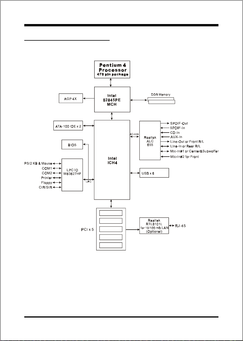
This board is designed with Intel® 845PE chipset. The Intel® 845PE chipset consists
of the Memory Controller Hub (MCH and the I/O Controller Hub (ICH4 .
Memory Controller Hub (MCH)
The MCH provides the interconnect between the AGP, DDR SDRAM and the
system logic. It integrates:
- Supports for single processor with a data transfer rate of 400/533/533+MHz.
- Supports dual channel of 200/266/333/333+ DDR SDRAM up to 2GB.
- 4X 1.5V AGP interface (Only support 1.5V on AGP interface .
- Downstream hub link for access to the ICH4.
I/O Controller Hub (ICH4)
The I/O controller Hub provides the I/O subsystem with access to the rest of the
system. Additionally, it integrates many I/O functions:

Introduction
Page 1-3
- Upstream hub link for access to the MCH
- 2-Channel Ultra ATA/100 Bus Master IDE controller
- USB controller
- SMBus controller
- LPC / Flash BIOS interface
- PCI 2.2 interface
- Integrated System Management Controller
Accelerated Graphics Port (AGP)
The AGP slot on the board is compliant with the new AGP 2.0 specification. This
new specification enhances the functionality of the original AGP specification by
allowing 4X data transfers ( 4 data samples per clock resulting in maximum band-
width of 1GB/s. In addition, it defines 1.5 volt power supply operation. Complying
with this specification, this board supports external AGP-4X cards with Fast Write
Transactions. Only 1.5V AGP cards are supported.
Ultra ATA/66/100
The ICH5/R provides an Ultra ATA/66/100 Bus Master IDE controller. This controller
supports Ultra ATA/66/100 protocols which are ideal to support demanding applica-
tions such as real-time video, multimedia, and a high performance operating system.
A new IDE cable is required for Ultra ATA/66/100; this cable is an 80-pin conductor
cable which is backward compatible with ATA/33 connectors.
Hardware Monitoring
Hardware monitoring enables you to monitor various aspects of the system operation
and status. The features include CPU temperature, voltage and fan speed in RPMs.
LAN (Optional)
This mainboard is optionally mounted with a LAN chipset. It allows the mainboard to
connect to a local area network by means of a network hub.

Introduction
Page 1-4
Mainboard Form-Factor
This board is designed with ATX form factor - the latest industry standard for
chassis design. The ATX form factor is essentially a Baby-AT baseboard rotated
90 degrees within the chassis enclosure and a new mounting configuration for
the power supply. With these changes the processor is relocated away from the
expansion slots, allowing them all to hold full length add-in cards. ATX defines a
double height aperture to the rear of the chassis which can be used to host a
wide range of onboard I/O. Only the size and position of this aperture is defined,
allowing PC manufacturers to add new I/O features (e.g.; TV input, TV output,
joystick, modem, LAN, audio, etc. to systems. This will help systems integrators
differentiate their products in the marketplace, and better meet your needs.
By integrating more I/O down onto the board and better positioning the hard
drive and floppy connectors material cost of cables and add-in cards is
reduced.
By reducing the number of cables and components in the system, manufac-
turing time and inventory holding costs are reduced and reliability will
increase.
By using an optimized power supply, it's possible to reduce cooling costs
and lower acoustical noise. An ATX power supply, which has a side-
mounted fan, allows direct cooling of the processor and add-in cards making
a secondary fan or active heatsink unnecessary in most system applications.
PCI slots
Expandable I/O
Figure 2: Summary of ATX chassis features
CPU socket
Single chassis
fan for system
AT X
Power
Supply
ATX power connector
IDE connectors
AGP slot
3 1/2-inch
Bay
5 1/4-inch
Bay
ATX 12V power
connector
Floppy
connector

Introduction
Page 1-5
Power-On/Off (Remote)
This board has a 20-pin ATX and a 4-pin ATX12V power supply connector (Figure
4 . For power supplies that support the Remote On/Off feature, this should be
connected to the mainboard front panel PW_ON connector for the computer power
On/Off button.
The board has been designed with Soft Off" function. You can turn off the system
in two ways: by pressing the front panel power On/Off button or using the "Soft
Off" function (incorporated in the mainboards onboard circuit controller that can
be controlled by an operating system such as Windows®XP/ME/2000/98.
Note: For maintaining the DDR SDRAM power during STR (ACPI S3) fun tion, it is
strongly re ommended to use power supplies that have a +5VSB urrent of (>
=) 2A. Please he k the 5VSBs spe ifi ation that has been printed on the
power supplys outer ase.
Note: The board requires a minimum of 250 Watt power supply to operate. Your
system onfiguration (amount of memory, add-in ards, peripherals, et .) may
ex eed the minimum power requirement but to ensure that adequate power is
provided, use a 300 Watt (or greater) power supply. Also your power supply
must support 4-pin ATX 12V onne tor.
I/O Shield Connector
The board is equipped with an I/O back panel (Figure 3 . Ensure that your computer
case has the appropriate I/O cutout.
Figure 3: I/O ports
PW-ON
Case (chassis) Po er ON/OFF button (PW-ON)
POWER SUPPLY
12V 4-pin
20-pin
Figure 4: Simple ATX po er ON/OFF controller
USB 2.0
port
PS/2 Mouse
PS/2 Keyboard
COM1
Parallel Port
RJ45 L N Joystick/Midi port
COM2
(Optional)
Mic-in/Center&Subwoofer(Pink)
Line-out/Front out (Lime)
Line-in/Rear out (Light Blue)

Introduction
Page 1-6
Figure 5: System Block Diagram
System Block Diagram

.A=JKHAI
Page 2-1
Section 2
FEATURES
Mainboard Features
Processor
Socket 478 Intel® Pentium® 4 and Celeron processors from 1.7GHz up to
3.2 GHz with 400/533/533 MHz front Side Bus
Supports Hyper-Threading Technology
To enable the Hyper-Threading Technology function on your computer
system requires ALL of the following platform components:
)CPU: An Intel® Pentium® 4 Processor with HT Technology.
)Chipset: An Intel® Chipset that supports HT Technology.
)BIOS: A BIOS that supports HT Technology and has it ena led.
)OS: An operating system that supports HT Technology.
Performance will vary depending on the specific hardware and software
you use. See <http://www.intel.com/info/hyperthreading> for information
including details on which processor support HT Technology.
Chipset
Intel 845PE Chipset (845PE ICH4)
Main Memory
Two 184-pin DDR DIMM sockets for PC1600/PC2100/PC2700 (DDR200/
266/333/333 ) DIMMs
Supports up to 2GB memory size
BIOS
Flash EEPROM with Award BIOS
- ACPI v2.0 compliant
- S3 (Suspend to DRAM) sleep-state support
- SMBIOS (System Management BIOS)
v2.2 compliant
- Supports Power failure recovery
- Able to wake the computer from specific states by Power switch, PME#,
RTC alarm, USB, PS2 K/B, PS2 Mouse, Modem Ring-in COM#1

.A=JKHAI
Page 2-2
Onboard PCI Devices
LAN --> Integrates 10/100Mps Fast Ethernet controller with onboard
Realtek RTL8101L LAN Chipset
IDE --> 2 ordinary IDE Port with PIO/Ultra DMA-33/66/100 for up to 4
devices
Legacy IO Controller
Winbond W83627HF LPC IO controller with floppy, printer, game, serial
and CIR/SIR interface
udio
Six channel audio with analog and digital output using Realtek ALC655
AC97 CODEC
- AC97 v2.3 compliant
- In 2-CH mode, supports Line-In (Light blue), Line-Out (Lime) and Mic-In
(Pink) at rear panel
- In 6-CH mode, supports Rear speaker out (Light blue), Front speaker out
(Lime) and Center&Subwoofer speaker out (Pink) at rear panel
- Supports CD-In, Aux-In and S/PDIF-in/out interface
- Supports Line-out and Mic-In for front panel
- Supports automatic jack-sensing
Peripheral Interfaces
)At Rear Panel
PS/2 keyboard and mouse ports
One RJ45 LAN connector (Optional)
Two USB2.0 ports
One Parallel (printer) port
Two Serial port
One Game port
Three Audio jacks
(Optional)

.A=JKHAI
Page 2-3
)Onboard connector and pin-header
One floppy drive connector
Two IDE connectors
Four extra USB2.0 ports
One CD-IN and One AuX-IN connector
One S/PDIF in/out connector
One IR connector
One Front Panel Audio connector
Two Fan connectors
Front Panel Controller
Supports Reset & Soft-Off switches
Supports HDD & Power LEDs
Supports PC speaker
Expansion Slots
One AGP slot supporting 1.5v 4X AGP card
- AGP v2.0 compliant
Five PCI slots with Bus Master support
- PCI v2.2 compliant
Other Features
Magic Health a BIOS H/W monitoring utility for voltage, temperature and
fan-speed sensing displayed during POST
EZ Boot A simple shortcut to select the boot device, e.g. hard drive, CD-
ROM or floppy without entering CMOS setup
Supports exclusive KBPO (Keyboard Power On) function
Excellent Overclocking capabilities through
- subtle frequency tuning on FSB

.A=JKHAI
Page 2-4
- Supports complete Asynchronous FSB/Memory and Asynchronous FSB/
AGP, PCI scheme for overclocking
Form Factor
305mm x 210 mm ATX size

Installation
Page 3-1
Section 3
INSTALLATION

Installation
Page 3-2
Mainboard Layout

Installation
Page 3-3
Easy Installation Procedure
The following must be completed before powering on your new system:
3-1. CPU Installation
3-2. Jumper Settings
3-3. System Memory Configuration
3-4. Expansion Slots
3- . Device Connectors
3-1 CPU Installation
Step 1
Open the socket by raising the actuation
lever.
Figure 1
Step 2
Align pin 1 on the CP with pin 1 on
the CP socket as shown in the
illustration above. The CP is keyed to
prevent incorrect insertion. Dont force
the processor into the socket. If it does
not go in easily, check for mis-orienta-
tion and reinsert the CP .
Make sure the processor is fully
inserted into the socket.
Figure 2
Pin 1

Installation
Page 3-4
Figure 3
Step 4
Apply thermal compound to the top of
the CP and install the heatsink as
shown.
Step
Install the cooling fan assembly. Press
the two clips in the direction of the
arrows shown in Figure 5 to secure the
assembly to the CP socket.
Step 6
Plug the CP fan into the CP fan
connector.
The installation is complete.
Figure 4
Figure 5 Figure 6
NOTES:
Damage to Intel PentiumTM 4 processors might result if installed with
incorrect CP fan and heatsink assemblies. se Intels design thermal
solution shown in the illustrations above: an active heatsink; an extruded
aluminum heatsink base; and a fan attached to the top of the fin array.
Apply heatsink thermal compound or paste to the CP to avoid CP
overheating and damage.
In accordance with Intel Corp. specifications, do not install a CP over
50 times to avoid bending the pins and damaging the CP .
Step 3
Close the socket by lowering and
locking the actuation lever.

Installation
Page 3-5
3-2 Jumper Settings
JCMOS:
Settings:
1-2: Normal(Default)
2-3: ClearCMOS
Clear CMOS data Jumper
If the CMOS data becomes corrupted or you
forgot the supervisor or user password,
clear the CMOS data to reconfigure the
system back to the default values stored in
the ROM BIOS.
To CMOS Clear data, please follow the steps below.
1. Turn off the system.
2. Change the jumper from 1-2 to 2-3 position
for a few seconds.
3. Replace the jumper on to the 1-2 position.
4. Turn on the system and hold down the <Del>
key to enter BIOS setup.

Installation
Page 3-6
<Figure 7>
<Table 1>
3-3 System Memory Configuration
Memory Layout
The mainboard accommodates two PC1600//PC2100/PC2700 184-pin DIMMs (Dual In-
line Memory Modules):
Supports up to 2.0GB of 200/266/333/333+MHz DDR SDRAM.
Supports unbuffered non-ECC DIMMs.
Supports configurations defined in the JEDEC DDR DIMM specification.
Figure 7 and Table 1 show several possible memory configurations.
NOTES:
When FSB is 400MHz, DDR200/266 are supported.
When FSB is 533/533+MHz, DDR266/333/333+ are supported.
sing non-compliant memory with higher bus speeds
(overclocking) may severely compromise the integrity of the
system.
*DDR SDRAM supports 64, 128, 256, 512MB and 1GB DIMM modules
using 512Mb te hnology.
DDR DIMM 1
DDR DIMM 2
Bank 0/1 DDR
Synchronous
DRAM
Bank 2/3
yromeMlatoT 1MMIDRDD
)1/0knaB(
2MMIDRDD
)3/2knaB(
BG1=
mumixaM
*MARDSRDD
,BM652,BM821,BM46
1X*BG1,BM215
enoN
BG2=
mumixaM
*MARDSRDD
,BM652,BM821,BM46
1X*BG1,BM215
*MARDSRDD
,BM652,BM821,BM46
1X*BG1,BM215
Table of contents
Other Intel Motherboard manuals

Intel
Intel DZ77BH-55K User manual

Intel
Intel D410PT User manual

Intel
Intel DZ68ZV User manual

Intel
Intel ATC6430M User manual

Intel
Intel DX79SI User manual

Intel
Intel DH67VR User manual

Intel
Intel BX80623I52500 User manual

Intel
Intel D810E2CA3 User manual

Intel
Intel H61 Express User manual

Intel
Intel D845GBV Technical manual

Intel
Intel D845HV User manual

Intel
Intel D915GMH User manual

Intel
Intel 82563EB Guide

Intel
Intel D945PLNM User manual

Intel
Intel DG41KR User manual

Intel
Intel AR-B1760 User manual

Intel
Intel D945GCCR User manual

Intel
Intel D915GEV User manual

Intel
Intel DQ35JO - Desktop Board Executive Series... User manual

Intel
Intel DH87MC User manual