INTELLI HEAT anglia User manual

ENG
INSTALLATION
AND INSTRUCTIONS
Thermodynamic
fluid-filled radiators
Location
Installation
Connection
Safety
Use With Intelligent Thermostat
www.intelligentheat.co.uk
ANGLIA
CALI
CALIDUS

2 3
PAGE 11
PAGE 6
PAGE 6
PAGE 3
PAGE 4
PAGE 5
PAGE 6
PAGE 7
PAGES 8 - 9
PAGES 10 - 11
PAGE 12
PAGE 13
PAGE 14
PAGE 15
PAGE 16
PAGE 17
PLEASE PAY SPECIAL ATTENTION
USER GUIDELINES
ELECTRICAL INSTALLATION GUIDELINES
INSTALLATION INSTRUCTIONS
RADIATOR WALL MOUNTING GUIDELINES
ANGLIA RADIATOR WALL MOUNTING
CALI & CALIDUS RADIATOR WALL MOUNTING
CALI, CALIDUS AND ANGLIA WEIGHTS AND SIZES
THERMOSTAT AND PROGRAMMER GUIDELINES
CALI RADIATOR ANALOGUE THERMOSTAT CONTROLS
CALIDUS & ANGLIA THERMOSTAT PROGRAMMING
LCD PROGRAMMER TECHNICAL CHARACTERISTICS
PROVISION FOR USER NOTES
Table of contents
www.intelligentheat.co.uk
Thank you for choosing our product
We trust that you will be fully satisfied with the performance and quality
of your new Intelli Heat product, but to ensure your maximum comfort
and safety please ensure that you thoroughly study and understand
all the information and advice contained throughout this document.
All Rights on this USER GUIDE are Reserved © No reproduction is permitted - Intelli Heat and intellyGreen are patented brands

Do not touch the radiator or thermostat when you are
wet and do not install any part of the system outdoors.
Our radiators are safe and water resistant, nevertherless we strongly advise
you not touch the radiator or thermostat with wet hands or feet, or when any
part of you is wet. This product is designed for interior use only.
CLEANING: Always ensure the radiator is turned off at the main power
source, clean with a soft, non abrasive damp cloth. Never wash with water or
allow water to go onto the thermostat or any electrical connection.
Do not cover or lay any material over the radiator.
Do not lay any material over the radiator especially if it is damp or wet. Never
place furniture or any other object against the radiator. Always ensure that
the radiator is installed in an open area to allow optimum heat to be radiated,
do not install where curtains will be drawn over the radiator.
Pay attention when children are around.
Although our radiators are designed for ease of use and safety, like with any
other electrical or heating product, always exercise caution where children
are concerned. We also strongly advise you not to allow children or any
unsuitable person to tamper with any electrical connection or to operate any
controls associated with the appliance.
Never hang from the radiator or load it with weight.
Never pull, sit on, hang from or load the radiator with any weight. Such
practice may damage the radiator or cause it to come loose from the wall or
the wall fitting attachments, which could cause serious injury. Also to avoid
such injury, alway check from time to time to ensure that the radiator is
securely fixed to the wall.
Do not tamper with or modify the product.
Never attempt to alter or modify a radiator or any associated control system
or electrical connection. Such action would invalidate the warranty and may
cause system malfunction or injury. If required, our products should only be
repaired by an appropriately qualified person. Do not attempt any
maintenance or replace any damaged components. Do not apply stickers.
PAGE 3
CAUTION - ALWAYS HANDLE HEAVY ITEMS WITH CARE.
Depending on the size and model, some radiators can be very heavy,
therefore always take every safety precaution when stroring, transporting
and installing heavy radiators. We strongly advise that at least two people lift,
move and install heavy radiators, and that each radiator is professionally and
securely fixed to the wall using the appropriate method suitable to the
construction of the wall.
PLEASE PAY SPECIAL ATTENTION
All Rights on this USER GUIDE are Reserved © No reproduction is permitted - Intelli Heat and intellyGreen are patented brands

Waste electrical and
electronic equipment
(WEE)
Please act responsibly when disposing of any
electrical item. The WEE Directive aims to both
reduce the amount of electrical and electronic
equipment being produced and to encourage
everyone to reuse, recycle and recover it. Intelli
Heat as a manufacturer fully complies with the
UKs WEE Regulations. For further information
should you intend to dispose of an electrical
item please visit:
www.environment-agency.gov.uk.
Height
(mm)
ENGLISH
The original Thermodynamic
It is essential that you keep this user guide and all
documentation related to this product for further
reference.
IMPORTANT
FOR YOUR SAFETY
IN ACCORDANCE WITH THE REGULATIONS:
The heating element inside each radiator is equiped
with an integrated fuse. In case of overloading the
fuse melts and cuts off the power supply. The heater
element must then be changed by the manufacturer
or by a qualified electrician familiar with such
products. If needed, please contact your dealer.
MAINTENANCE
To ensure the perfect functioning of you radiator and
to ensure its durability, it is necessary to clean the
radiator at least once a year. Before you start the
cleaning process you must ensure that the power
supply is turned off at the main power source.
Clean the main body of the radiator with a damp soft
cloth using, if required, a non agressive and non
abrasive cleaning product. Clean the front and side
surfaces including inbetween any groves and fins, and
where possible, the back surfaces of the radiator.
Do not use any water or cleaning products when
cleaning the thermostat, use a slightly damp soft cloth
to wipe it clean ensuring that you do not apply too
much pressure. When cleaning the thermostat hold it
with one hand as you clean it to ensure that any
connection to the radiator is not disturbed.
Never allow any water, cleaning fluid or spray cleaning
product to go onto the thermostat or any other
electrical connection.
PLEASE NOTE
FUNCTIONING
A radiator may sometimes produce light clicking
sounds, this is nothing to be concerned about. These
sounds are produced by the interlocking of certain
types of thermostats.
A radiator may also produce light cracking sounds, this
is also nothing to be concerned about. This is due to
the expansion of the various metals the radiator is
composed of. This is a natural occurence associated
with electric heaters, so it does not signal a fault.
IF YOU SELL OR TRANSFER
Should you decide to sell or transfer this product to
a third party, this manual must also be passed to the
new owner to enable a full understanding of the
product and to ensure safety and adherence to these
guidelines. Also, should any warranty period still be in
effect, faliure to comply with this will invalidatethe
warranty.
PAGE 4
USER GUIDELINES
We strongly advise you to seek
expert advice if you are unsure
about any aspect of the radiator
installation process.
All Rights on this USER GUIDE are Reserved © No reproduction is permitted - Intelli Heat and intellyGreen are patented brands
fluid filled radiators with Intelligent Thermostat

.
.
volume 3
0.60 m
0.60 m
0.60 m
volume 2
volume 1
ELECTRICAL INSTALLATION GUIDELINES
CAUTION
These radiators are double insulated therefore
they are not earthed and the radiator cable does
not include an earth wire (yellow green).
Each radiator cable has a Live (BROWN) Neutral
(GREY) and a BLACK wire, which is the PILOT
WIRE.
NEVER CONNECT or aLlow accidental
connection of the BLACK PILOT WIRE to the
Live, Netural or Earth connections of the power
supply. If this occurs it will damage the
thermostat beyond repair.
The black wire is for connection to an extenal
programmer only, this could be a hard wired or
wireless system, please contact Intelli Heat for
advice on such systems.
If a pilot wire programmer system is not used,
the black wire must be properly
isolated/insulated to avoid any connection to
the live, netural or earth of the power supply.
A USEFUL TIP!
Installation that involves simply positioning a radiator
next to a power supply will keep the cost of installation
down. For example, by replacing a storage heater with
your new Intelli Heat radiator in the same position.
Should you decide to position your new radiator
where thereis not a power supply, the cost of
installation will increase. Therefore, if convenient, it's
best to plan your installation according to the available
power supply.
PAGE 5
All electrical installation must comply with the
current regulations, standards and code of
practice in effect in the country where the
product is to be installed.
The electrical connection of these radiators
must be carried out using a standardized
junction box. In both kitchens and bathrooms,
the connection box must be installed at least 25
cm above the floor.
These radiators must be supplied with 230 V -
50 Hz single-phase and neutral. No other power
supply can be used.
Each radiator must be supplied with a
dedicated power cable protected with a 10 amp
circuit breaker for appliances ranging from 500
W to 2000 W power rating.
INSTALLATION RULES
ELECTRIC RADIATORS IN WET ROOMS
Kitchens and Bathrooms
These radiators are "Class II" insulated
therefore earthing is prohibited.
These radiators are "IP24" rated and are
therefore protected from splash water.
These radiators can be installed in bathrooms
volumes 2 and 3 provided that no electrical unit
can be touched by a person using the bath-tub
or shower.
The circuit supplying the radiator in a wet room
must be protected by a 30 milli amp Residual
Current Device to ensure safety.
Bathroom Volumes
A radiator installed in a wet room must be
connected to the electricity supply using a
standardized junction box without the use of a
socket outlet. Earthing is prohibited.
All Rights on this USER GUIDE are Reserved © No reproduction is permitted - Intelli Heat and intellyGreen are patented brands
ESSENTIAL TARRIF INFORMATION
ECONOMY 10 (UNRESTRICTED) is reccomended to
ensure minimal running costs, Ecomony 7 is not
suitable. If you change your tarrif from Economy 7
to another tarrif you MUST ensure that the circuits
supplying Intelli Heat radiators provide an
unrestricted suply of electricity.
1.
3.
2.
4.

L = Live
Brown color
N = Neutral
Grey color
P = Pilot wire
(ONLY for connec tion to a
pilot wire pr ogrammer)
Black color
Program ming
sy st em
RADIATOR CONNECTION
Figure 1
INSTALLATION INSTRUCTIONS
PAGE 6
CAUTION:
Before any installation
or work on the electrical
circuit, you must cut off the
power supply from the
circuit breaker or from the
main circuit breaker.
Always double check to
ensure that no wire is live.
L N P
We strongly advise that all electrical installation be
carried out by an appropriately qualified electrician.
NEVER connect the PILOT WIRE to a
EARTH, LIVE or NEUTRAL connection.
The BLACK Pilot Wire is for pilot wire
programming use only.
COLOUR CODE: (see diagram below)
Power connection: BROWN to lIVE, GREY to
NEUTRAL, BLACK to, if used, to a PILOT WIRE
programmer ONLY.
Check that the radiator is correctly connected to the
electricity supply, then test the various functions of
the thermostat. For temperature control and
programming, please refer to the table of contents to
locate the appropriate instructions for your system.
In the event of faulty operation, first check that the
appliance is properly connected to the power supply.
If everything seems to be in order, you should first
contact the person who installed your system, if they
are unable to assist, you should then contact
the supplier or the manufacturer.
TO AVOID RISK OF ELECTROCUTION:
Do not tamper with, modify or dismantle a radiator,
the thermostat or any associated control or electrical
system. Do not put any metal object into the
thermostat.
The electrical cable is connected to the system by the
manufacturer, it is not replaceable and is supplied as
a standard length, it should not be extended or
shortened.
Do not pull the electrical cable, twist it or wedge it
behind or in the fins of the radiator.
Should the electrical cable become damaged or the
electrical installation was not carried out correctly or
accordance with the regulations, you are at risk of
suffering serious wounds which could be life
threatening.
If the electrical cable is damaged, it must be replaced
by the manufacturer or by one of their after sales
service personnel, or by a fully qualified electrician
who is familiar with this type of system.
STARTING
SAFETY INSTRUCTIONS
WARNING:To avoid overheating, never cover a
radiator and never position it below a power socket.
These radiators are filled with an accurate quantity of
a special Thermodynamic fluid. Any repairs that
require the fluid tank to be opened must only be
carried out by the manufacturer or by one of their
approved after sales service personnel. The
manufacturer must be contacted in the event of any
leakage of fluid.
PLEASE NOTE
Connection of the PILOT WIRE to the LIVE, NEUTRAL or
EARTH of the power supply will destroy the
thermostat. If the pilot wire is not to be connected to
a pilot wire programmer then it must be correctly
isolated/insulated to ensure that this does not occur.
ELECTRICAL WIRING
These radiators are "CLASS II" double insulated.
The electric cable of these radiators do not include an
Earth wire. Earthing is prohibited, ground connection
is strictly forbidden. For thermostats that are equiped
with a pilot wire which is for connection to a pilot wire
programmer, it is essential to ensure that the LIVE and
NEUTRAL wires are correctly connected.
All Rights on this USER GUIDE are Reserved © No reproduction is permitted - Intelli Heat and intellyGreen are patented brands

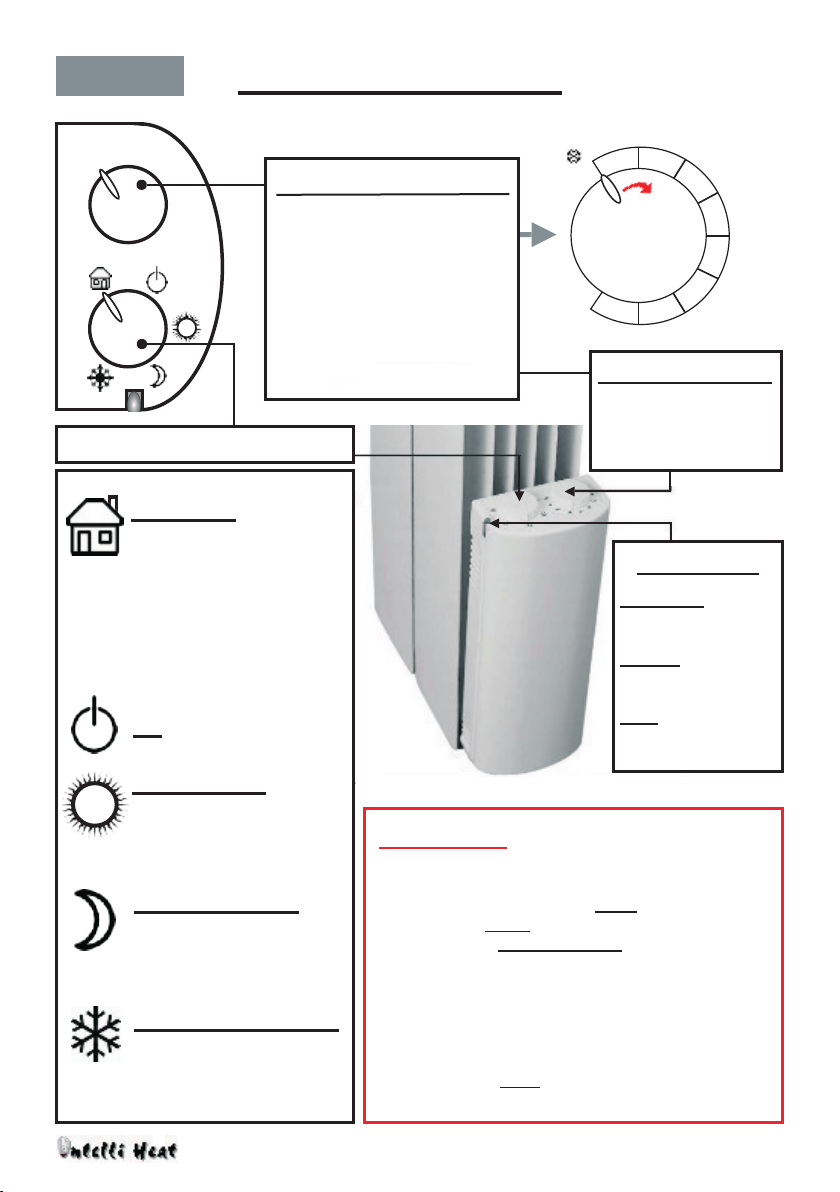
POSITIONING RADIATOR
PAGE 7
RADIATOR WALL MOUNTING GUIDELINES
Do not attempt to attach the radiator to a wall that is
unable to bear the weight of the radiator or is
damaged, damp or unsound. If in doubt we strongly
advise you to seek expert advice to establish if in fact
the construction of the wall can support the weight of
the radiator and to determine the correct and safest
method of installation.
Before drilling holes, always check that no electricity
cable or water pipe exists within the wall at the point
where you intend to drill. This can be achieved by
using an appropriate sensor available from most
builder's merchants or DIY stores.
Always take every safety precaution when lifting,
stroring, transporting and installing heavy radiators.
We strongly advise that at least two people handle
and install heavy radiators.
Before drilling holes in a wall for screw-fixing, always
ensure that you use a drill bit that is specifically
desigend to drill the construction material of the wall.
The radiator shoud not be positioned under a deep
shelf, however it can be positioned under a shelf that
is roughly the same depth that the radiator will
extend to once fitted to the wall, provided that a
distance of at least 100m exists between the top of
the radoator and the underside of the shelf.
If the radiator is positioned in the corner of a room or
next to a peice of furniture, a distance of at least
100mm the must exist between side of the radiator or
the thermostat and the wall or peice of furniture.
Do not position the radiator close to, for examle, the
back of a sofa, or where curtains are likely to be
draped over it. Do not position under a power socket.
For best results install the radiator in a location that
will allow optimum radiation of heat, for example if
a single radiator is used in a room, it should be
positioned it in a centrally, unobstructed location.
The radiator must be positioned so that the bottom of
the radiator is between 100mm to 150mm above the
floor.
LOCATION AND POSITIONING
We advise for these radiators to be fixed to the wall
by a competent tradesman. Although the proceedure
is designed to be simple and quick, it should not be
carried out by someone who is unfit or inexperienced
in such matters.
CAUTION
If more than one radiator is to be installed in a room,
each radiator must be positioned at least three
meters apart from each other. Please contact your
supplier if unsure about the positioning of one or
several radiators in a room.
A
ATTACHING TO THE WALL
B
Please study the instructions applicable to your
radiator model before starting the wall mounting
process, see pages 8 to 11.
A = Minimum 100mm
B = Minimum 100mm - Max 150mm
The radiator must be fixed to the wall horizontally
and level, always use a spirit level to mark out the drill
holes and fixing position.
Use only the fixing attachments supplied with
the product, see pages 8 - 10.
Always use the correct type of drill bit, rawlplugs and
screws suitable for the construction material of the
wall. Always ensure that these are the correct size to
support the weight of the radiator and to ensure the
secure and safe attachment of the radiator to the
wall, if in doubt you must seek expert advice.
The radiator must be fixed to the wall so that the
thermonstat is positioned at the bottom right hand
side of the radiator.
Please seek expert advice if you are unsure about any
aspect of the wall mounting process.
All Rights on this USER GUIDE are Reserved © No reproduction is permitted - Intelli Heat and intellyGreen are patented brands

25
40
15
20
20
10
8
BRACKET LENGTH = H
DISTANCE BETWEEN FIXING CENTRES = E
WALL MOUNTING BR ACKETS
A = min. 207 mm - max 257 mm
B= 358 (for 600 mm high radiator)
C= 158 (for 400 mm high radiator)
Figure 4
10
10
Bc
AA
Figure 3
ANGLIA RADIATOR WALL MOUNTING
WALL MOUNTING BRACKETS
PAGE 8
ANGLIA RADIATORS
BRACKETS FOR 600mm
HIGH RADIATORS
PLEASE NOTE: The design of the brackets
and fittings included with your product
may vary slightly from those isllustrated.
CAUTION! Measurements may be different than
stated. The size of the brackets, the position of the screw holes
and fixing points that fix to the the fixing points on the back of
the radiator may vary. The distance between the fixing points
on the back of the radiator may also vary. If they do, the actual
positioning/fixing of brackets to the wall will need to be
adjusted accordingly to correspond with fixing points on back
of radiator and to ensure that the distance from the bottom of
the radiator to the floor is a minimum of 100mm to a maximum
of 150mm when the radiator is fixed to the wall.
DRILLING
DIMENSIONS
*
D= To correspond with fixing points
on the back of the radiator
PLACEMENT OF WALL MOUNTING BRACKETS
All Rights on this USER GUIDE are Reserved © No reproduction is permitted - Intelli Heat and intellyGreen are patented brands
BRACKETS FOR 400mm
HIGH RADIATORS
D
D
Placement of brackets on
the wall, two distance from
wall radiator mounting
options , turn brackets to
face left or right accordingly.
Fixing points at rear of radiator
Always use a spirit level to ensure that the wall
brackets and the radiator are fixed to the wall level.

2 + 2
1 + 1
B
DA
Radiator fi tting
Rad iat or
dim ens ions
D
D
B
Drilling
dimensions
F I GU R E 6
F I GU R E 5
F I GU R E 7
ANGLIA RADIATOR WALL MOUNTING
PAGE 9
CAUTION!
Anglia steel radiators are heavier than our aluminium radiators, with the larger models (higher watts)
being very heavy. Please see the weights table on page 12 of these instructions. Because of this
every safety precaution must be taken to ensure that each radiator is correctly and securely fixed to,
and mounted on the wall. DO NOT UNDER ANY CIRCUMSTANCES ATTEMPT MOVE, FIX TO THE WALL,
OR REPOSITION THIS HEATER WITHOUT SEEKING EXPERT ADVICE.
We recommend fixing this radiator to walls of solid brick, block or stone construction by first drilling
correctly positioned holes in the wall using an 8 mm drill bit, inserting No 10 size plastic security
rawlplugs (hole to be 15 mm deeper than the length of the rawlplug), then screwing the brackets to
the wall through the bracket holes provided using No 10 screws. Do not attach the radiator to a wall
that is damaged, damp or unsound.
We do not recommend fixing this radiator to a stud partition wall (plasterboard on a timber frame).
However this is possible provided that the brackets are screw-fixed to the wall at the points where
the interior wood framework is located. Use No 10 woodscrews and ensure that the screws go
directly and centrally into the timber framework. It might be possible to attach smaller (lighter)
models to plasterboard walls however you must seek expert advice to establish if in fact the
construction of the wall can support the weight and to determine the correct method of installation.
Before drilling holes, always check that no electricity cable or water pipe exists within
the wall at the point where you intend to drill. This can be achieved by using an
appropriate sensor available from most builder's merchants or DIY stores.
All Rights on this USER GUIDE are Reserved © No reproduction is permitted - Intelli Heat and intellyGreen are patented brands

◘◘
◘
◘◘
◘
◘◘
◘
◘◘
◘
◘◘
◘
◘◘
◘
◘◘
◘
◘◘
◘
◘◘
◘
◘◘
◘
◘◘
◘
◘◘
◘
◘◘
◘
320 mm/6EL
480 mm/8 Elements
640 mm/10 Elements
960 mm/14 Elements
1040 mm/15 Elements
800 mm/12Elements
15 14 12 10 8 6 6 8 10 12 14 15
◘◘
◘
◘◘
◘
◘◘
◘
◘◘
◘
15 14
14 15
10 12
6 8
CALI & CALIDUS RADIATOR WALL MOUNTING
Each CALI and CALIDUS radiator is supplied with wall mounting triangular fittings with attached holding hook,
each with three holes allowing screw-fixing to the wall. See placement dimensions below and on page 11.
Radiator sizes 600w to 1500w are supplied with three fittings, two fittings are to be screw-fixed to the wall at
the top and one to be screw-fixed to the wall positioned below and central to the two upper fittings.
Radiator sizes 1800w and 2000w are supplied with four fittings, two fittings are to be screw-fixed to the wall at
the top and two to be screw-fixed to the wall below and in line with the two upper fittings.
The radiator must be level when attached to the wall. To achieve this, first determine the distance from the
floor to the position on the wall where the top fittings are to be fixed (refer to page 11). Using that as a reference
point, place one fiitting level with the single hole facing downwards on the wall. Then make a pencil mark onto
the wall through one of the top holes of the fitting. Using a long spirit level (or long straight peice of wood with
a spirit level placed on top) line up the top of the spirit level with the pencil mark, adjust the spirit level to ensure
that it is level, then draw a faint pencil line onto and accross the wall. This line will act as a guide to position the
left and right fittings to ensure they are both level, it wll also allow you to mark the correct distance between the
two top fittings, as specified on the diagram below.
[C]
[D]
[F]
[G]
[E]
[H]
The numbers on the diagram above represent the the number of elements for each
size of radiator, for example a 600w CALI and CALIDUS radiator has 6 elements.
PAGE 10
1800w and 2000w only 1800w and 2000w only
WARNING: Do not attach the radiator to a wall that is usuitable to bear the weight or is damaged, damp
or unsound. You must seek expert advice to establish if in fact the construction of the wall can support the
weight and to determine the correct and safest method of installation. When drilling holes, always check that
no electricity cable or water pipe exists within the wall at the point where you intend to drill. This can be
achieved by using the appropriate sensor available from most builder's merchants or DIY stores.
All Rights on this USER GUIDE are Reserved © No reproduction is permitted - Intelli Heat and intellyGreen are patented brands

●●
●
12
3
●●
●
4
A
●●
●
●●
●
●●
●
●●
●
●●
●
●●
●
●●
●
6
5
B
CALI AND CALIDUS WALL MOUNTING
A= Distance from floor to top fixing reference level - 700 mm to 710 mm.
B= 500 mm The distance from top fixing reference level to bottom fixing level.
C= Refer to diagram with measurements and information on page 10.
PAGE 11
●●
●C
Size 8 mm
DRILL BIT
Size 10 plastic
security rawlplug
Size 10 screw
●●
●
Ensure correct for wall type
Floor
All Rights on this USER GUIDE are Reserved © No reproduction is permitted - Intelli Heat and intellyGreen are patented brands

CALI, CALIDUS AND ANGLIA RADIATORS
Dimensions and Weights
PAGE 12
Width sizes include the thermostat at the side
All Rights on this USER GUIDE are Reserved © No reproduction is permitted - Intelli Heat and intellyGreen are patented brands
CAUTION
Always take every safety precaution when lifting, stroring, transporting and installing heavy
radiators. We strongly advise that at least two people handle and install heavy radiators.
Model Power (W) Fins Dimensions (mm) kg
CALIDUS 300W 300 4 580 x 370 x 96 9
CALIDUS 600W 600 6 580 x 530 x 96 12
CALIDUS 950W 950 8 580 x 690 x 96 16
CALIDUS 1200W 1200 10 580 x 850 x 96 20
CALIDUS 1500W 1500 12 580 x 1010 x 96 24
CALIDUS 1800W 1800 14 580 x 1170 x 96 28
CALIDUS 2000W 2000 15 580 x 1250 x 96 30
Model Power (W) Fins Dimensions (mm) kg
CALI 300W 300 4 580 x 370 x 96 9
CALI 600W 600 6 580 x 530 x 96 12
CALI 950W 950 8 580 x 690 x 96 16
CALI 1200W 1200 10 580 x 850 x 96 20
CALI 1500W 1500 12 580 x 1010 x 96 24
CALI 1800W 1800 14 580 x 1170 x 96 28
CALI 2000W 2000 15 580 x 1250 x 96 30
Model Power (W) kg
ANGLIA CLASSIC 500W 500 26
ANGLIA CLASSIC 750W 750 30
ANGLIA CLASSIC 1000W 1000 33
ANGLIA CLASSIC 1250W 1250 36
ANGLIA CLASSIC 1500W 1500 43
ANGLIA CLASSIC 1750W 1750 44
Model Power (W) kg
ANGLIA CIRCEO 500W 500 26
ANGLIA CIRCEO 750W 750 30
ANGLIA CIRCEO 1000W 1000 33
ANGLIA CIRCEO 1250W 1250 36
ANGLIA CIRCEO 1500W 1500 43
ANGLIA CIRCEO 1750W 1750 44
1050 x 600 x 80
1250 x 600 x 80
1050 x 600 x 110
Dimensions (mm)
750 x 600 x 80
850 x 600 x 80
950 x 600 x 80
1050 x 600 x 80
1250 x 600 x 80
1050 x 600 x 110
Dimensions (mm)
750 x 600 x 80
850 x 600 x 80
950 x 600 x 80

i
!
!
40 - 80mm
YES NO!
The theromostat is class II protected
against splashes, it can be installed in
zone 2 and 3 in bathrooms but do not
splash water onto the thermostat or
any electrical connection.
Install a calibrated earth-leak circuit
breaker in accordance with current
norms.
never touch the thermostat when in
the shower or bath or when wet.
Never cover the ventilation holes on
the thermostat.
Never clean the thermostat with
water or a liquid cleaner.
We strongly reccomend that the thermostat's electric cable is connected to the main
power supply using a junction box (switched fused spur), Place the junction box at least
25cm above the floor, install the junction box behind or next to the the thermostat;
however it can be be fitted with an electrical plug and plugged into an electrical socket.
!
The installation must comply with
the current regulations and best
trade practice applicable to the
country where it is fitted.
When installing/removing the regulator verify that the main power supply is switched off.
!
!
The power supply circuit must be sectioned. Sectioning must be done using a multi-polar
devise sectioning all the power supply terminals. The sectioning distance between the
contacts of each terminal must be at least 3mm.
THERMOSTAT & PROGRAMMER GUIDELINES PAGE 13
i
ELECTRICAL WIRING: P l e a s e r efer to page 6.
WARNING: Never connect or allow the accidental connection of the BLACK PILOT WIRE to the Live, Netural
or Earth connections of the power supply. If this occurs it will damage the thermostat beyond repair.
All Rights on this USER GUIDE are Reserved © No reproduction is permitted - Intelli Heat and intellyGreen are patented brands
A) If under a shelf: Minimum 100 mm.
B) Distance from wall: Minimum 100mm.
C) Distance from floor:
Minimum 100mm - Maximum 150 mm.
A
B
C
Please read these instructions
thoroughly before installing
and using a radiator.
FOR YOUR SAFETY
INSTALLATION GUIDELINES
CONNECTING TO THE ELECTRICITY SUPPLY
Installation distance
from the wall:

Mode Selection Dial
THE CALI RADIATOR
PAGE 14
All Rights on this USER GUIDE are Reserved © No reproduction is permitted - Intelli Heat and intellyGreen are patented brands
CALI RADIATOR
13
5
7
9
•
•
•
•
Auto Mode
Off
Comfort Mode
Will operate according to
the temperature set on
the dial.
Background Mode
Maintains a temperature
of 3.5 degrees C lower
than the Comfort setting.
Maintains a temperature
of 7 degrees C.
Frost protection Mode
MODE SELECTION DIAL
WARNING!
This radiator is double insulated, therefore it does not need
to be earthed. The cable from the thermostat has a Live
(BROWN), Netural (GREY) and BLACK wire which is the
PILOT WIRE - NEVER connect or allow the accidental
connection of the BLACK PILOT WIRE to the Live or Netural
connections of the power supply or ANY Earth connections,
if thsi occurs it will damage the thermostat beyond repair.
The BLACK PILOT WIRE is a signal wire, it is only to be used
for connecting to an external programmer which can either
be a hard wired or wireless system, please contact Intelli
Heat for advice on such systems. If the BLACK PILOT WIRE is
not being used it MUST be properly insulated/isolated to
avoid any connection to a Live, Netural or Earth supply.
Indicator Light
NO LIGHT:
Off.
GREEN:
Background Mode.
RED:
Comfort Mode.
ANALOGUE THERMOSTAT CONTROL
Temperature Control
1
97
5
3
22°C
30°C
7°C
15°C
Turn clockwise to increase
temperature setting, turn
anti-clockwise to reduce
the temperature setting.
OPERATING INSTRUCTIONS
This scale is reliable when the
radiator is positioned in a
standard environment but it is
normal for the setting to vary
in order to achieve the same
ambient temperature in
different rooms:
TEMPERATURE DIAL
(Influence of Environment)
The radiator will operate
(if connected) in the
Comfort, Background or
Frost Protection Modes
at the times set by an
external programmer
such as the IntellyGreen
or ZoneRay systems.

PAGE 14
The device has four buttons. To switch on the device push the "On/off button".
The display will show the current time in the “Clock” mode, the temperature
setting is shown in the other modes. A small icon indicates the operating mode
Press the "Mode" button to change the operating modes (individual setting
options), the mode will change each time you press the "Mode" button.
Two different levels of temperaure can be set: T_high is the temperature setting for
the clock, pilot-wire and comfort modes; T_low is the temperature setting for the
night-reduction mode. In the relative operating mode the required temperature
can be set by pressing the Plus and Minus buttons. The flashing thermostat icon
shows that setting is in progress - please wait until it stops flashing before
you procede.
The two levels are also used by the programming modes as follows:
A lock child protection can be set. Press simultaneously the Plus and Minus buttons
for about 3 seconds to lock the keyboard. A small lock icon is displayed. To unlock the
keyboard, press simultaneously the two buttons for about three seconds once again.
Press the “Mode” and "Stand By" buttons simultaneously and hold for about 4
seconds to enter the configuration mode. The dot indicating the current day flashes:
Press the plus or minus button to set required day. Press “Mode” button once to
confirm. "Hour will start flashing, use plus or minus button to set then press the
"Mode" button to confirm.
Switch on the electricity:
When the device is on:
To change the operating mode:
Setting the temperature:
Child lock protection:
Setting daily & weekly programming:
Now an hourly sequence can be set for each day. Start with the
first day, select the sequence required using the plus or minus
buttons to define Comfort (full bar) or Night (empty bar) for
each hour.
Setting hourly programme for each day:
0 4 12 24
Press “Mode” button to confirm and repeat the procedure for every day of the week.
Child lock icon
This operating mode allows the user to set different
temperatures during the day. It is possible to set the
T_High temperature or the T_Low temperature. The
temperature levels and the hours can be programmed.
Programming the operating mode
CALIDUS & ANGLIA LCD THERMOSTAT PROGRAMMING
PAGE 15
All Rights on this USER GUIDE are Reserved © No reproduction is permitted - Intelli Heat and intellyGreen are patented brands
“Minutes” will now start flashing: as before use plus or minus button to set, then
press the "Mode" button to confirm.
Press the "Mode" button repeatedly to scroll through the options until the time is shown, then press the
“Mode” and "Stand by" buttons simultaneously and hold for about 4 seconds to enter the configuration
mode - then press the "Mode" button once, the hour will flash, press + or - to set the hour, press "Mode"
once to confirm, the minutes will then flash, press + or - to set, then press the "Mode" button to confirm.
On/off-Stand by button
If you need to change the time setting:

Power supply 230 V 50 Hz
Heating power 2000 W maximum
Insulation category II
Protection category IP24
Shock resistance IK10
Operating temperature 0 ÷ 50°C
Storage temperature -20÷80°C
Operating humidity levels 20÷95% without any condensation
Temperature control Analogical using a knob
Temperature selection range 7 ÷ 30°C
0.5°C
NF (French Norms) Performance Category C
ENGLSH
TECHNICAL CHARACTERISTICS
LCD INTELLIGENT THEROMSTAT
Maximum error I selected tremerature
PAGE 16
TWO YEAR WARRANTY
Your Intelli Heat product comes complete with a two year
manufacturers warranty on the main body and all electronics.
This warranty is valid from the date of your purchase.
This warranty covers any fault that may arise due to the faulty
manufacture of the product. It does not cover any fault that
may be caused by miss-use, accidental or intentional damage
caused by the purchaser or other persons after purchase, or
incorrect installation. Please ensure that you keep all
documentation relating to this product including your invoice
as this will be required should you need to use this warranty.
Thank you for choosing our product and we wish you a lasting,
trouble free and enjoyable use of your new Intelli Heat system.
All Rights on this USER GUIDE are Reserved © No reproduction is permitted - Intelli Heat and intellyGreen are patented brands

PAGE 17
Date of purchase: _______________________________________
System purchased: _______________________________________
SUPPLIER DETAILS
Company Name: _______________________________________
Telephone Nos: _______________________________________
Email Address: _______________________________________
Contact Name: _______________________________________
INSTALLER DETAILS
Date of installation: _______________________________________
Company Name: _______________________________________
Telephone Nos: _______________________________________
Email Address: _______________________________________
Contact Name: _______________________________________
NOTES
PLEASE KEEP A RECORD
All Rights on this USER GUIDE are Reserved © No reproduction is permitted - Intelli Heat and intellyGreen are patented brands

INTELLI HEAT©Ltd
Unit 18 Napier Place, Stephenson Way, Thetford, Norfolk IP24 3RL
Manufacturers of Advanced Heating Systems
www.intelligentheat.co.uk
www.intellygreen.com
All Rights on this USER GUIDE are Reserved © No reproduction is permitted - Intelli Heat and intellyGreen are patented brands
This manual suits for next models
2
Table of contents
Other INTELLI HEAT Heater manuals
Popular Heater manuals by other brands

Sentiotec
Sentiotec Concept R Instructions for installation and use

THE RADIATOR COMPANY
THE RADIATOR COMPANY Ovali Bath Fitting instructions

Generac Power Systems
Generac Power Systems MAC 750F owner's manual

CLIMAVENETA
CLIMAVENETA i-LIFE SLIM 102 Installation, user and maintenance manual

Sennheiser
Sennheiser SI 1015 quick guide

BE
BE HL062B user manual