Intelli-metry THERMO User manual

THERMO - Manual Ver 01.00
TEMPERATURE / HUMIDITY
MONITOR and LOGGER
Manual
THERMO
TEMPERATURE / HUMIDITY
MONITOR and LOGGER
Manual
– Ver 01.00
THERMO
Page 1
TEMPERATURE / HUMIDITY

THERMO
THERMO - Manual Ver 01.00 Page 2
PRODUCT LIMITED WARRANTY
We warrant our products to be free from defects in material and workmanship for a period
of one (1) year from date of shipment. Any product found to be defective within this time
period may be returned to our factory, freight prepaid, with prior return authorization for
repair or replacement (at our discretion) at no charge (with the e ception of rechargeable
batteries). Our liability under this warranty is limited to the repair or replacement of the
defective product and in no event shall Intelli-metry or anyone on its behalf be liable for
consequential or indirect damages to goods, property, equipment or personnel. Nor shall
we be liable for damages to equipment or for personal injury caused by misuse, accidental
damage, alteration, improper installation, or unauthorized opening of the equipment.
Under no circumstances will we be responsible for any direct, indirect or consequential
damages due to errors in measurement or failure of our product to perform properly.
LEGAL DISCLAIMER NOTICE
Specifications of the products displayed herein are subject to change without notice.
Intelli-metry or anyone on its behalf, assumes no responsibility or liability for any errors or
inaccuracies. Information contained herein is intended to provide a product description
only. No license, e press or implied, by estoppel or otherwise, to any intellectual property
rights is granted by this document. E cept as provided in our terms and conditions of sale
for such products, we assume no liability whatsoever, and disclaim any e press or implied
warranty, relating to sale and/or use of our products including liability or warranties relating
to fitness for a particular purpose, merchantability, or infringement of any patent, copyright,
or other intellectual property right. The products shown herein are not designed for use in
medical, life-saving, or life-sustaining applications. Customers using or selling these products
for use in such applications do so at their own risk and agree to fully indemnify us for any
damages resulting from such improper use or sale. Risk of loss of the products shall pass to
the buyer when the products are tendered by us for shipment to the buyer. THIS
WARRANTY CONSTITUTES OUR EXCLUSIVE WARRANTY. THERE ARE NO OTHER
WARRANTIES, EXPRESS OR IMPLIED, INCLUDING ANY WARRANTY OF MERCHANTABILITY OR
FITNESS FOR A PARTICULAR PURPOSE.

THERMO
THERMO - Manual Ver 01.00 Page 3
Table of Contents Page
1. Description................................................................................................................4
2. Package Contents......................................................................................................5
3. Sim Card Installation.................................................................................................6
4. Unit Installation.........................................................................................................7
5. Unit Startup...............................................................................................................8
5.1 Normal Startup............................................................................................8
5.2 Low Battery Startup.....................................................................................8
6. Live Value Display......................................................................................................9
6.1 Battery Level................................................................................................9
6.2 Mains Status...............................................................................................10
6.3 Signal Strength...........................................................................................10
6.4 Communications Activity...........................................................................10
6.5 Unit ID........................................................................................................11
6.6 Time...........................................................................................................11
6.7 Channel Name.........................................................................................11
6.8 Channel Value.........................................................................................11
6.9 Channel Valid Range...............................................................................11
7. Bootload Function....................................................................................................12
8. Switching The Unit On.............................................................................................12
9. Switching The Unit Off.............................................................................................12
10. Sensors...................................................................................................................13
10.1 Temperature Sensor................................................................................13
10.2 Temperature And Humidity Sensor.........................................................14
11. Message Que Handling..........................................................................................15
12. Unit Configuration..................................................................................................15
12.1 Configurable Settings...............................................................................15
13. SMS Messages........................................................................................................16
14. Technical Information............................................................................................17
14.1 THERMO Unit Mechanical Information...................................................17
14.2 THERMO Unit Technical Data..................................................................17
14.3 Temperature Sensor Technical Data........................................................18
14.4 Temperature Sensor Mechanical Information.........................................18
14.5 Temperature And Humidity Sensor Technical Data.................................19
14.6 Temperature And Humidity Sensor Mechanical Information..................19

THERMO
THERMO - Manual Ver 01.00 Page 4
1. Des ription
The THERMO data logger monitors temperature and humidity, and transfers the
information to a secure web based database on pre-determined intervals.
Typical applications include fridges, cold rooms, air conditioned server rooms etc.
The system consists of a THERMO Unit, 1-Wire sensor(s), power supply and a web based
central database called Signal Tower. The THERMO unit can be installed in a convenient
location and the sensor(s) are positioned where critical temperature and / or humidity
measurements are to be taken.
The unit is equipped with two 1 wire sensor inputs. It can accommodate two temperature
sensors or one temperature and humidity combination sensor.
Using Signal tower, each sensor channel can be set up to record temperature or humidity
levels at configurable intervals. In addition, high and low thresholds are set up, and alarms
are sent by either or SMS and e-mail. An audible alarm is also activated on the THERMO
unit.
Other alarms include Mains Failure, Mains Restored, Battery Low, Unit Tamper, Sensor
Disconnect, Sensor Connect, etc.
The secure database is used to do all reporting, e-mailing of graphs, setting up of alarm
conditions, maintaining client and notification recipients etc.
Typical Application
THERMO - Manual Ver 01.00
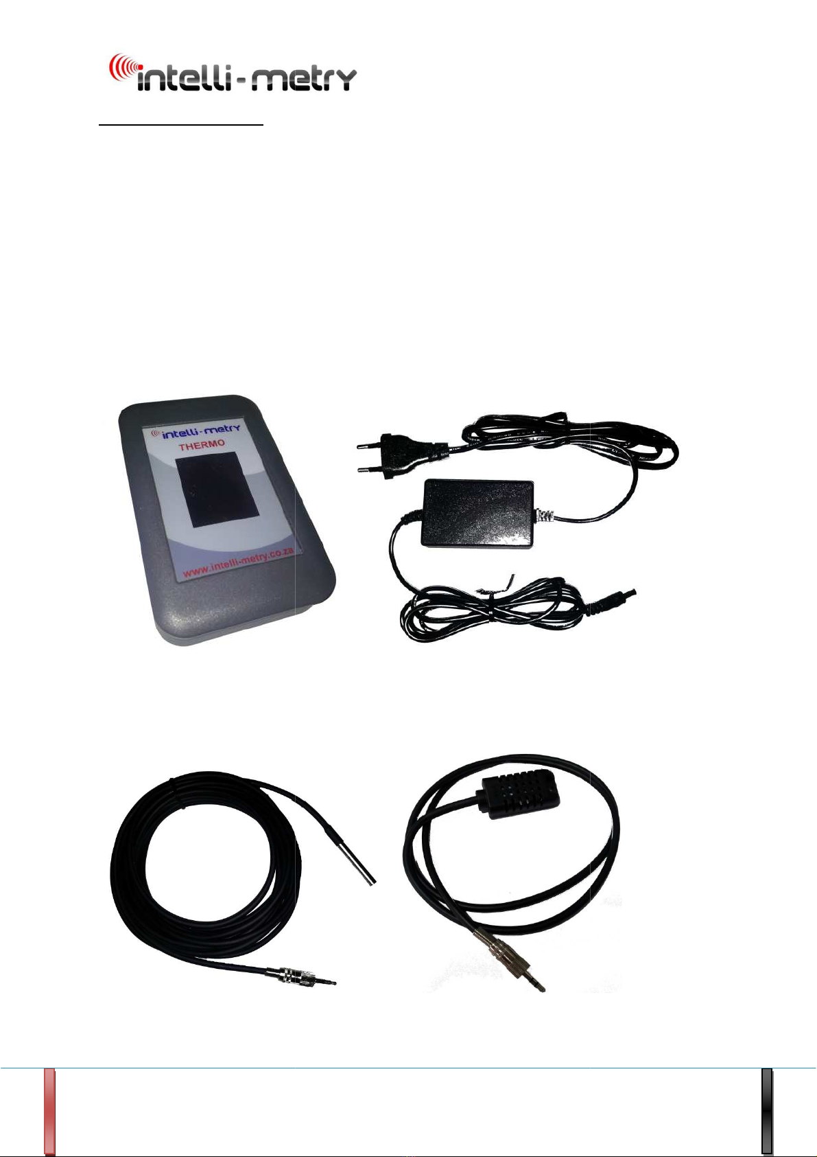
2. Pa kage Contents
1 THERMO Unit
1 Power Supply
Sensor Options:
1 or 2 Temperature Sensors
THERMO
Temperature Sensor
1 or 2 Temperature Sensors
or 1 Temperature / Humidity S
ensor
Power S
upply
Temperature Sensor
or
Temperature / Humidity Sensor
THERMO
Page 5
ensor
upply
Temperature / Humidity Sensor

THERMO
THERMO - Manual Ver 01.00 Page 6
3. Sim Card Installation
Make sure the sim card's pin code request is disabled.
The sim card must be able to send SMS messages and have Data (GPRS).
Remove the 4 grey round screw covers at the back of the unit and unscrew the 4 screws.
Remove the back cover and insert the sim card into the sim card holder on the pcb. Check
that the sim card is properly inserted.
Please make sure that the battery is connected to the provided white 3 pin connector on
the pcb before closing the unit.
Put the back cover back and close the unit using the 4 screws. Refit the grey screw covers.
Note: The unit can also use a sim chip type sim card. This must be fitted by the
manufacturer of this unit.
Sim ard holder

THERMO
THERMO - Manual Ver 01.00 Page 7
4. Unit Installation
Install the temperature sensors and route the wires to the Thermo unit. Label the wires
close to the connector with the input number (1 or 2) that it should be connected to and the
description of temperature being measured. E . 1 - Fridge, 2 - Freezer, 2 - Aircon 1, 1 -
Room Temp.
The sensors will take a while to reach the new environment’s temperature, so install them
first to give them time to adjust.
Put or mount the Thermo unit in the desired position and plug the power supply into a 220V
AC power source. Connect the power supply’s DC Jack to the Thermo unit. The unit will
switch on. Please see Unit Startup(Section 5) for more information.
Connect the sensor cable(s) to the unit on the unit. The top connector is for channel 1 and
the other connector is for channel 2. Temperature and humidity combination sensors can
be connected to any channel connector. These sensors use two channels on the unit and
will display the relative humidity on channel one and the temperature on channel two.
Mains Status LED
Channel 2 Sensor Conne tor
Channel 1 Sensor Conne tor
Power Conne tor
Alive / Transmit Indi ator

THERMO
THERMO - Manual Ver 01.00 Page 8
5. Unit Startup
5. Normal Startup
The unit starts with a blue screen and display THERMO startup in the first line. The unit
shows the status of the startup process and will show
THERMO Startup
Swit hing GSM ON... = GSM module is switched on
GSM ON... = GSM module is on
SIM dete ted! = Sim card has been detected
SIM registered! = Sim card has registered on the network
GSM Signal = xx% = GSM Signal strength is xx
5.2 Low Battery Startup
Battery harging If a unit starts up with this screen it means that
Please wait.... the internal battery level is too low for the unit
to work correctly. It will charge the battery up to a safe
level and will then start up. This battery charging
process can take anything from a few minutes up to 1
hour, depending on how discharged the battery is.

THERMO
THERMO - Manual Ver 01.00 Page 9
6. Live Value Display
On this screen the live values of sensors connected, valid ranges, channel names, battery
level, mains status, GSM signal strength, communications activity, unit id and time is
displayed.
6.1 Battery Level:
The charge state of the battery is indicated by this indicator.
Full battery
50% Capacity remaining
<30% Capacity remaining
Battery Level
Mains Status
Signal Strength
Communi ation
A tivity
Unit ID
Time
Channel 1 Name
Channel 1 Value
Channel 1 Valid
Range
Channel 2 Name
Channel 2 Value
Channel 2 Valid
Range

THERMO
THERMO - Manual Ver 01.00 Page 10
6.2 Mains Status:
The mains status is indicated by this indicator.
Mains on
Mains off
NOTE: When the mains fail, the backlight is switched off after 5 seconds to save battery
power. Press on the display to switch the display backlight on for 5 seconds.
6.3 Signal Strength:
This indicates the GSM signal strength.
Signal strength less than 20%
Signal strength between 20% and 40%
Signal strength between 40% and 60%
Signal strength between 60% and 70%
Signal strength between 70% and 80%
Signal strength better than 80%
6.4 Communi ations A tivity:
This indicator indicates when the unit is communicating with the server via GPRS.
Data is transmitted to the server
Acknowledgement is received from the server

THERMO
THERMO - Manual Ver 01.00 Page 11
6.5 Unit ID:
The unit's ID is displayed in the top right hand corner. Typically something like OWC00001.
6.6 Time:
This is the unit's time. It is updated once per minute. When the unit is switched on this will
be blank but it will be displayed once the unit has updated its time from the server.
6.7 Channel x Name:
This is the name of the channel. It will give you an idea of were the sensor connected to the
channel is installed. E amples are : Fridge1, Big Freezer etc.
6.8 Channel x Value:
The live value read from the sensor is displayed here. If the value is displayed in green then
the value is within the normal configured range. The value will be displayed in red if it falls
outside of the valid range.
6.9 Channel x Valid Range:
This is the valid range for the specific channel. The values are configurable via Signal Tower.

THERMO
THERMO - Manual Ver 01.00 Page 12
7. Bootload Fun tion
Firmware Upgrade
Downloading...
. % Complete = Downloading progress from 0.0% to 100.0%
Done! = This is displayed after the download was
successful. Do not do anything, leave the unit
as is with everything connected and mains
switched on.
The Thermo unit has the functionality to be able to update its own firmware over the air. It
is initiated by the manufacturer when there is new firmware updates or features. All other
functions on the unit will be disabled while it is downloading the new firmware and
installing it onto the device. After the bootload is complete the unit will restart with the
new firmware. No interaction is needed by the user. It usually takes about 30 minutes in
total to complete but this can take up to 1 hour when the GSM signal strength is low or if
network problems is e perienced. If the unit is unable to download the new firmware it will
try a few times and then it will restart and continue to work on the previous firmware
already loaded on it.
8. Swit hing The Unit On
Take the power supply and plug it into the 220V AC wall socket. Take the wire on the other
side of the power supply and plug the DC jack into the Thermo unit. The unit will switch on.
Please see Unit Startup(Section 5) for more information.
9. Swit hing The Unit Off
To switch off the unit, unplug the DC jack from the Thermo unit. The unit will send a unit
off message and then it will switch off. It can take up to 5 minutes for a unit to switch off
after the DC jack was unplugged.
THERMO
THERMO - Manual Ver 01.00 Page 13
10. Sensors
There are two sensors that is compatible with the Thermo. A temperature sensor and a
temperature and humidity combination sensor. These sensors are described in detail
below.
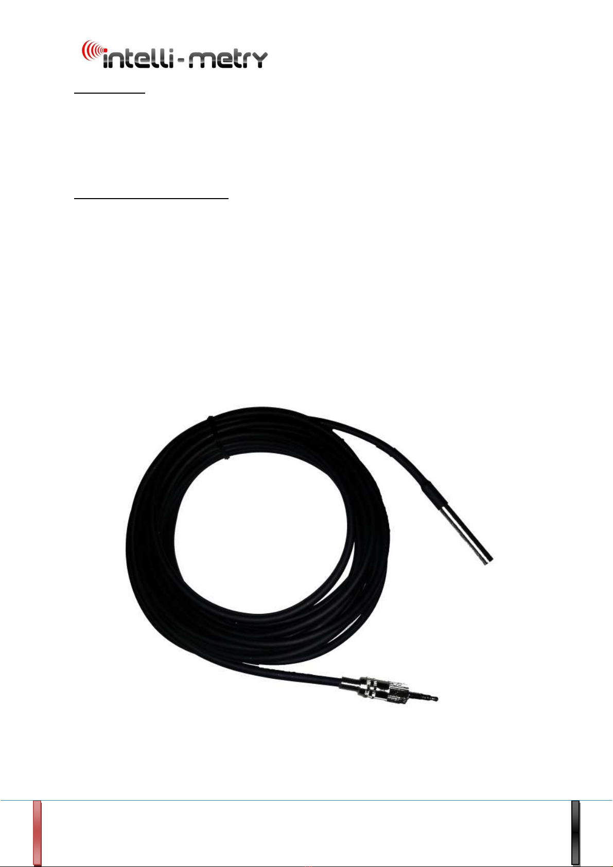
10.1 Temperature Sensor
This sensor measures temperature of air or liquid and is waterproof. The measurement
range is -55°C to +125°C with resolution of 0.1°C and accuracy of ± 0.5
o
C between -10°C
and +85°C. Standard cable length is 2 meter or 5 meter and can be e tended up to 40
meters. The Thermo unit can support two of these sensors and each sensor uses one
channel.
Typical applications where this sensor can be used:
•Fridges
•Cold rooms
•Temperature controlled environments
1- Wire Temperature Sensor Image

THERMO
THERMO - Manual Ver 01.00 Page 14
10.2 Temperature And Humidity Sensor
This sensor measures temperature and humidity of air. The temperature measurement
range is -40°C to +80°C with resolution of 0.1°C and accuracy of ± 1.0
o
C. The humidity
measurement range is
0%RH – 99.9%RH
with resolution of 0.1%RH and accuracy of ± 3%.
Standard cable length is 1 meter and this is the ma imum length the cable can be. The
Thermo unit can support one of these sensors and uses two channels on the unit. Channel 1
is humidity and channel 2 is temperature.
Typical applications where this sensor can be used:
•Server rooms
•Air conditioned environments
1 - Wire Temperature And Humidity Sensor Image

THERMO
THERMO - Manual Ver 01.00 Page 15
11. Message Que Handling:
All SMS messages and important messages will be send immediately. If there is a problem
with the GPRS communications to the server, the important messages will be send with SMS
to the server.
The messages that is used for logging will be stored in a buffer and will be send with GPRS
when it is available. If GPRS fails it will store the messages and retry once a hour to resend.
There is a setting to set the que length, once this que is full there is two options. Delete the
oldest messages or SMS them. Only the messages that can not fit in the que anymore will
be deleted or SMS'ed depending on the configuration. If GPRS starts to work again then
everything in the que will be send with GPRS starting with the oldest messages first.
12. Unit Configuration
To setup the unit configuration, visit www.intelli-metry.co.za, and follow the Programming
link.
Allow 48 Hours for settings to be updated.
12.1 Configurable Settings:
Defaults
Unit Address or description message Unit's ID
Health Message Time :00
Reporting SMS Cell Numbers 1 to 10 NA
Sensor 1 Name (ma imum 10 characters) Sensor
Sensor 1 High Alarm Message (ma imum 5 characters) High
Sensor 1 Low Alarm Message (ma imum 5 characters) Low
Sensor 1 Level in Range Message (ma imum 5 characters) Ok
Sensor 1 High Alarm Level (Temperature / Humidity) 25
Sensor 1 Low Alarm Level (Temperature / Humidity) -40
Sensor 1 Logging interval 20 Minutes

THERMO
THERMO - Manual Ver 01.00 Page 16
Sensor 2 Name (ma imum 10 characters) Sensor 2
Sensor 2 High Alarm Message (ma imum 5 characters) High
Sensor 2 Low Alarm Message (ma imum 5 characters) Low
Sensor 2 Level in Range Message (ma imum 5 characters) Ok
Sensor 2 High Alarm Level (Temperature / Humidity) 25
Sensor 2 Low Alarm Level (Temperature / Humidity) -40
Sensor 2 Logging interval 20 Minutes
13. SMS Messages:
E amples: Unit Switched On at ABC goods, Demo Road JHB
Mains Off at ABC goods, Demo Road JHB
Please note that every one of these messages can be enabled or disabled for SMS sending.
•Unit Switched On
•Unit Switched Off
•Mains On
•Mains Off
•Battery Ok
•Battery Low
•Airtime Low (airtime below R10. Only for prepaid sim cards)
•Health Test
•Sensor Connected
•Sensor Disconnected
•Value High Alarm
•Value Low Alarm
•Value In Range (after alarm condition)

THERMO
THERMO - Manual Ver 01.00 Page 17
14. Te hni al Information
14.1 THERMO Unit Me hani al Information
14.2 THERMO Unit Te hni al Data
Unit Size………………………..……………………………………………………………………….. 117mm 73mm 24mm
DC Supply Voltage………………………………………………………………………………….. 8 - 15VDC 1A
Data interface………………………………………………………………………………………… GPRS and SMS
User Software……………………………………………………………………………………….. Signal Tower
Sensor e citation output voltage…………………………………………………………… 3.6 – 4.2VDC
Unit operating range……………………………………………………………………………… 0°C to 60 °C
Battery backup time (logging frequency dependant) ……………………………. > 6 Hours
Measurement rate……………………….………………………………………………………… Once every 5 seconds

THERMO
THERMO - Manual Ver 01.00 Page 18
14.3 Temperature Sensor Te hni al Data
Temperature measurement range…………………………………………………………. -55°C to +125°C
Accuracy………………………………………………………………………………………………… ± 0.5°C (-10°C to +85°C)
Resolution…………………………………………………………………………………………….. 0.1°C
Measurement medium………………………………………………………………………….. Air, various liquids
Sensor cable length……………………………………………………………………………….. 5m (40 m Ma imum)
14.4 Temperature Sensor Me hani al Information

THERMO
THERMO - Manual Ver 01.00 Page 19
14.5 Temperature And Humidity Sensor Te hni al Data
Temperature measurement range…………………………………………………………. -40°C to +80°C
Accuracy……………………………………………………………………………………………….. ± 1°C
Resolution…………………………………………………………………………………………….. 0.1°C
Humidity measurement range……………………………………………..………………. 0%RH to 99.9%RH
Accuracy……………………………………………………………………………………………….. ± 3%
Resolution…………………………………………………………………………………………….. 0.1%RH
Measurement medium…………………………………………………………………………. Air
Sensor cable length………………………………………………………………………………. 1m (1m Ma imum)
14.6 Temperature And Humidity Sensor Me hani al Information
Table of contents


