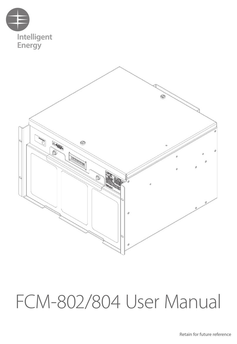
Intelligent Energy FCM-801 User manual

FCM-801 User Manual
Read before installation and use.

Contents
1 Safety and warnings 3
1.1 In case of an emergency
1.2 Warning
2 Product specification 4
3 Parts of the FCM-801 5
4 Product interface 6
4.1 Interface specification
5 FCM-801 overview 7
6 Connections 8
6.1 Electrical configuration
6.2 Air supply
6.2 Hydrogen fuel
6.4 Hydrogen connection
6.5 Communication connection
6.6 CAN connection
6.7 Status indication
7 FCM-801 commands and status 11
7.1 Module Enable / Reset
7.2 Module Run
7.3 FCM-801 status
7.4 FCM-801 software states
8 Operation of FCM-801 13
8.1 FCM-801 operation summary
8.2 Anode purge
8.3 Performance Optimisation Cycle
8.4 Standby state
8.5 Fault state
9 Faults 14
9.1 Procedure to reset the fault
10 Installation and set up 15
10.1 Label information
10.2 Mechanical mounting points
10.3 Mechanical protection and covers
10.4 Vibration and shock loads
10.5 Air supply and ventilation
10.6 Hydrogen connection
10.7 Hydrogen fuel physical requirements
11 Trouble-shooting guide 19
11.1 Check for fuel leak
11.2 Fuel check procedure
11.3 Electrical system check procedure
11.4 Stack temperature check procedure
11.5 Filter change procedure
12 Maintenance procedures 23
12.1 User maintenance
12.2 Contact Intelligent Energy Product Support
13 Control parameters
and standard factory setting 24
14 Spare parts, storage and disposal 26
15 EU Declaration of Conformity 27
Disclaimer X
The CE label shows that the product complies with the
basic requirements of the applicable directives. For the
declaration of conformity contact the manufacturer at
servicing@intelligent-energy.com

3
Safety and warnings1
The Fuel Cell Module 801 (FCM-801) uses hydrogen gas to provide electrical DC power.
It should only be installed or maintained by personnel who have been trained to use
the product safely by Intelligent Energy.
1.1
1.2
In case of an emergency
This User Manual is intended as a general guidance only and does not purport to address the specific situations that could potentially arise from the use
of fuel cell systems and their usage in connection with all stationary applications. The recipient is responsible for ensuring that all personnel have read
and understood this User Manual before being allowed to handle, operate, install and store any equipment supplied by Intelligent Energy.
The recipient must ensure that any personnel responsible for operating fuel cell stationary applications are suitably trained and certified in compliance with
any applicable local, state and federal laws and regulations and good industry practice. The recipient is responsible for complying with any relevant health
and safety policies and procedures that may apply to the operation of stationary applications, and use and storage of hydrogen on any sites.
Intelligent Energy warrants to the recipient and it will repair and replace any defective equipment resulting from the authorised use of the equipment
provided. Notwithstanding the above, Intelligent Energy, to the fullest extent permitted by law, accepts no liability (including liability in respect of any
error or defects in the fuel cell system) for any damage caused as a result of Recipient’s unauthorised use of the equipment provided. The recipient
acknowledges that the manner in which the equipment is stored, used or operated is not under the control of Intelligent Energy Limited.
Intelligent Energy has made every effort to ensure that this User Manual is accurate and disclaims liability for any inaccuracies or omissions that may
have occurred.
· No naked flames or sources of ignition in the vicinity of the FCM-801 or hydrogen
operation areas
· Pressurised hydrogen present, highly flammable
· Ensure hydrogen supply can be isolated in the case of an emergency
· Direct current voltage is present
· Unit should be inspected for damage prior to use
· Fault diagnosis should be carried out by trained and competent personnel only
· Do not remove the air filter while operating
· Do not remove the external covers
· Keep operational area free from combustible materials
· Do not obstruct air flow to the inlet or exhaust
· For use in ventilated indoor environment
· For use in weather protected outdoor environment; must protect from wind
and rain ingress
· Environmental protection required from snow, excessive dust and vegetation
· Do not use this fuel cell if any part has been under water. A flood damaged fuel cell
is potentially dangerous; attempts to use the fuel cell can result in fire or explosion.
1 Stop power production from the fuel cell by disconnecting the FCM-801 Enable pin.
2 Isolate the DC supply (application specific).
3 Isolate the fuel supply (application specific).
– Do not store or use gasoline or other flammable vapours and liquids in the vicinity
of this or any other appliance.
– Installation and service must be performed by a qualified installer, service agency
or the gas supplier.
WARNING: FIRE OR EXPLOSION HAZARD
Failure to follow safety warnings exactly could result in serious injury, death or
property damage.

4
Performance Rated net power 11.2kW @ 48V or 0.96kW @ 24V
Output voltage regulation to ETS 300-132-2
Rated current 25A @ 48V or 40A @ 24V
Emissions Water vapour in warm exhaust air 2
Fuel Fuel type Hydrogen gas
Fuel pressure 500mbar.g – 700mbar.g
Fuel consumption Less than 60g per kWh 3
Fuel storage External storage available separately
Compatible with reformer technology or compressed
hydrogen gas
Fuel composition 99.9% gaseous hydrogen or better 4
Operations and
maintenance
User interface Options available 5
Start-up time Less than 10s
Automatic start/stop Operation governed by factory configurable time,
voltage and current levels in ‘Run’ state. Level set to suit
application battery and load. 6
Manual start/stop Interface connections provided for ‘Enable/Reset’ and
‘Run’ switch or signal. Accessory switches available.
IP rating IP20
Certification Health monitoring
Certification
Options available 7
CE, FCC
Physical Mass ~10kg
Max dimensions 225mm (W) × 300mm (H) × 550mm (D)
Connections, gas G1/8 parallel BSP threaded port with face seal, female
Connections, electrical Power leads 2 × 8AWG (8mm2) 1 × Positive cable,
1 × Negative/earth cable, 1 × CAN hi/low/gnd,
1 × LED driver, 1 × FCM Run input, 1 × FCM Enable input
Normal operating
conditions
Altitude 0 – 4000m 8
Operating ambient
temperature range
+5°C to +40°C
Relative humidity 10% to 90% 9
Storage temperature -40°C to +70°C
1 Hybrid battery provides power for start-up, shut-down and during performance
optimisation cycles.
2 No production of CO, CO2or NOx. Contains safety permitted trace levels of hydrogen.
3 Achieved at 25°C, beginning of life.
4 According to quality characteristics of Type 1, Grade E and Category 3 hydrogen fuel
specified in BS ISO 14687-3:2014(E).
5 CAN interface can be provided.
6 Typically hybridised with external battery allowing higher combined peak power.
Available load power reduced during battery charge. Multiple units may be operated
in parallel to increase power.
7 Options available for continuous health monitoring and predictive maintenance
scheduling for high system availability.
8 Rated power to 1500m. Power de-rate commences above 1500m.
9 Rated power from 30%. Power de-rate commences below 30%.
Product specification2

5
Parts of the FCM-8013
Power cables
Carry handle
Air filter
Communication Port
Hydrogen inlet
Power cables
Grab handle
Air filter fixings
Exhaust air
Inlet air
The major components of the FCM-801 are:
Rear view

6Product Interface4
Performance Function Specification
Hydrogen inlet
500mbar.g – 700mbar.g
Average flow rate 16 slpm
(peak flow 80 slpm for <1sec during purge)
Fuel supply G1/8 parallel thread, with
face seal
Air inlet
0 – 6,500 slpm
5 – 40°C
Ambient air filtration and
supply
170 × 240mm duct
Exhaust air
0 – 6,500 slpm
5 – 60°C
Air exhaust to ambient 150 × 150mm duct
Power connection
15.0 – 56.0V
Delivered current 0 – 40Amps
Start-up/Shutdown current draw 0 – 4Amps
Connection to DC bus 8AWG (8mm2)
Communication port
See Section 6.5
Max cable length 3m
Operational commands &
diagnostics
D type 9 way
4.1 Interface specification

7
FCM-801 overview5
5.1
The FCM-801 provides regulated DC at nominal 24V or 48V output
(configurable by the user at point of order). The FCM-801 will hold the DC
output at the nominal voltage while connected to an external battery or power
supply so that the system will act as a hybrid system. In the hybrid system, the
battery is used to provide power whilst the fuel cell starts, supports the load
during the fuel cell performance optimisation cycle process and in the standby
state. The nominal operating voltage is factory settable upon request.
Hydrogen gas should be provided at a regulated pressure to the module
inlet. The FCM-801 will generate power when it is given both Enable and Run
signals (see Section 7). During normal operation, the FCM-801 will conduct a
performance optimisation cycle where power delivery is briefly interrupted. In
this period the fuel cell will hybridise with the external battery (see Section 8.3).
When first connected the unit will assume that the battery will need to be
charged, unless the voltage indicates that the battery is already fully charged.
If, during normal operation the load drops to a low level (a pre-set level from
the configuration used) the fuel cell will enter a standby state (see Section 8.4).
This is designed to optimise fuel consumption. If the DC Bus voltage then dips
below a preset voltage, the fuel cell will restart.
This document is to help the users for operation, user maintenance and
installation of the FCM-801, however more information can be found in IEC
62282-3-300 Fuel cell technologies – Part 3.
Intelligent Energy is responsible for the safety of the FCM including its
connection points if used in accordance with this manual. The integrator is
responsible for the safety of the whole installation including hydrogen storage,
supply, batteries and any other equipment or infrastructure. A suitable safety
assessment will need to be undertaken for the entire installation.
Design certification
This product has been designed to meet the applicable European fuel cell safety
standard for stationary fuel cell power systems. It is intended for stationary
indoor and outdoor industrial use in non-hazardous (unclassified) areas.
For alternative applications including automotive, please consult
Intelligent Energy Ltd.

8Connections6
6.1
Note:
Warning:
Warning:
Warning:
Electrical configuration
The FCM-801 is supplied with cables which are 8AWG (8mm2). These should be
connected in a star configuration as shown in the figure below.
Do NOT electrically overload the FCM-801. Overloading will lead to excessive
load being drawn from the battery. Drawing excessive load may cause damage
to the equipment.
The battery circuit needs to be able to manage an in-rush of 100A of up to 5ms.
Do NOT disconnect the main power leads with the Enable signal present.
Do NOT use the FCM-801 if complete installation does not have a negative earth.
When the FCM-801 is running the power output will stay electrically live if
the power cables are disconnected. This therefore represents a high current
electrical hazard.
The battery pack should provide power at the desired voltage. The battery
pack should be capable of powering the load during module performance
optimisation cycle (see Section 8.3). For description of the command and signal
connections see Section 7 – FCM-801 Module Command and Status.
FCM-801 should be negatively earthed
FCM-801 electrical
connections
(viewed from rear)
Digital CommandsFCM Status
CAN Connection
Battery Negative
Earth Connection
Hybrid
battery
+
–
Battery overcurrent
protection fuse
~
Method of battery
isolation
DC Load /
Inverter

9
Connections6
6.4
6.3
Warning:
Warning:
6.2 Air supply
To produce electrical power the FCM-801 requires an unobstructed
air supply which must not be recirculated between the exhaust and inlet.
Refer to Section 10.5 – Ventilation.
Do not obstruct the air inlet or exhaust.
Do not recirculate the exhaust to the inlet.
The air should be free of the following contaminants:
· Sulphur
· Hydrocarbons
· Carbon Monoxide
· Ammonia
Hydrogen fuel
The FCM-801 has a G1/8 parallel thread connection. The hydrogen supply needs to
be regulated to 600mbar.g (±100mbar.g), and will see a maximum flow of 16 slpm.
When installing and operating hydrogen systems, hydrogen general safety
guidance should be considered:
· The hydrogen should be at least 99.9% pure and comply with the
specification: ISO 14687-3:2014 grade E category 3.
· ISO/TR 15916 basic considerations for the safety of hydrogen systems.
Hydrogen connection
The hydrogen connection to the system is below the air exhaust duct at the rear of
the module, see Section 2.1 – Product Interface. The hydrogen supply is connected
via a G1/8 parallel BSP thread with a face seal. A suitable mating connector must
be used.
The hydrogen pipework should be checked periodically for leaks, particularly when
connectors have been remade, such as cylinder exchange or installation.

10 Connections6
The pins for the connector are as follows:
CAN RTN (ground)
Positive Run
Negative Run
CAN Lo
Negative Enable / Reset
Positive Enable / Reset
CAN Hi
Status
Isolated ground
Communication connection
To operate the FCM-801, communications need to be provided through the D type
connector. The pins of the connector have the following functions:
Enable and Run command cables must be <3m in length.
Consideration to the communication earth should be considered when collecting
multiple FCM-801.
6.5
Pin No. Description Function
1 Enable / Reset (-ve) Negative for Enable / Reset line
2 Enable / Reset (+ve) Positive for Enable / Reset line
3 CAN high CAN pin
4 CAN low CAN pin
5 CAN return (ground) CAN reference
6 Run (-ve) Negative for Run line
7 Run (+ve) Positive for Run line
8 Status Status indicator
9 Isolated ground Ground pin
Note:
Warning:

11
6.7
Connections6
CAN connection
The CAN connection can be used to communicate with the FCM-801 using
Intelligent Energy’s proprietary CAN protocol. If multiple units are being
connected to a common bus, then the CAN connections must also be connected,
see Section 10 – Installation and set up.
Status indication
The design intent of the status indication is to provide a signal that the FCM is
producing power.
The FCM needs an external circuit to drive the status lamp. The external circuit
should be connected to:
· A power source
· FCM Status pin
· FCM Enable pin
6.6
FCM-801 commands and status
7
Module Enable / Reset
To enable the FCM-801 the Enable Negative needs to be connected to the
Positive Enable pin and held. This can be done by making a connection
between the Enable Positive and Negative pins (1&2). In the event of a fault
the Enable connection needs to be cycled to reset the fault status.
Module Run
To produce power, the Run Negative pin needs to be connected to the
Positive Run pin and held. This can be done by connecting the Run Positive
and Negative pins (6 & 7). (N.B: Enable must also be present). When the signal
is received, the FCM-801 will start and deliver power within 10 seconds,
provide power and maintain the battery voltage.
FCM-801 status
A continuous FCM-801 status signal will be present whilst the fuel cell is
running (with no fault present). FCM Status is an open collector output and 0V
signifies running. If the Run signal is present and there is no FCM-801 status
signal present then the FCM-801 is in Standby or Fault.
7.1
7.2
7.3

12
Modular
controller off
Modular
controller on
FCM-801 commands and status7
Please note the following points:
1 The small circle in each state box indicates the condition of the FCM-801
status pin. This is low (black: ) in all states apart from fuel cell running
where it is high (white: ).
2 In all states, removing the Enable signal returns the FCM-801 to the
module controller off state.
3 If the FCM-801 enters a fault condition the fault is latched. The Enable
line must be cycled to clear it.
4 For start and stop criteria see Section 13 – Control Parameters and
Standard Factory Setting.
Fault state
Fuel cell standby
Auto start criteria Auto stop criteria
Run on
Run off
Run off
Fault trip
State map for the FCM-801
Enable / Reset Off
Enable / Reset On
Enable / Reset Off
Fuel cell running
The states are transitioned as shown in the diagram below:
FCM-801 software states
The FCM-801 has 5 possible states:
· Controller off
· Controller on (run off)
· Fuel cell running
· Fuel cell standby
· Fault
7.4

13
Operation of FCM-8018
FCM-801 operation summary
The FCM-801 provides regulated DC at nominal 24V or 48V output to a battery
bus. The DC bus will be held at nominal voltage by a battery or external supply to
act as a hybrid system. In the hybrid system, the battery is used to provide power
to the FCM-801 whilst the fuel cell system starts. It supports the load during the
fuel cell performance optimisation cycle process and while the system is in the
standby mode. The nominal operating voltage is factory settable upon request.
The hydrogen pressure should be provided in a regulated state to the module
inlet. The FCM-801 will generate power when it is given both ‘Enable’ and ‘Run’
signals (see Sections 7.1 & 7.2) and detects DC bus and fuel pressure are present.
Anode purge
As the fuel cell operates, it is necessary to remove water and any impurities from
the anode (the fuel side of the fuel cell). This is done by exhausting a small amount
of hydrogen to the coolant air stream. The hydrogen is mixed with the air stream
so that, as the mixture exhausts the module, the concentration is low enough to
be safe (will not sustain flame). There is normally no impact on power production
during anode purge. The presence of sufficient air to sustain this safety dilution is
monitored and interlocked.
Performance optimisation cycle
During normal operation, the FCM-801 will periodically conduct an optimisation
cycle which improves the performance of the fuel cell. Multiple cycles are
triggered in rapid succession at start-up. Cycles occur less than 15 times an hour
during running. Power production is reduced or suspended for up to 12 seconds
during the cycle so an external power source may be needed to briefly provide
power to the load.
Standby state
It is undesirable for fuel cell durability and efficiency to operate at very low power.
The system can enter standby state based on the configuration parameters. If
there is more than one power source connected to the DC bus (such as a mains
grid or photovoltaic array) with a higher output voltage than the FCM Delayed
stop over voltage parameter can switch the unit to Standby. Similarly if there is no
load present the Delay stop under current parameter can switch over to Standby,
the intension of this feature is to boost the system fuel efficiency (See Section 8.6).
Once in standby mode the FCM will restart and provide power if the battery
voltage dips to Delay (or immediate) Start under voltage parameters.
It is important that the configuration is correct for the target installation.
Particularly with regard to type of battery to be used.
8.1
8.2
8.3
8.4
Note:

14 Operation of FCM-801
Faults
8
9
Procedure to reset the fault
If the FCM-801 has a fault it will disconnect the internal DC-DC converter and stop
providing power. To reset a fault follow the procedure below:
9.1
8.5
8.6
Detailed Instruction Critical Point Comments
Check that the load
is disconnected
Installation specific
Switch the Reset signal to ‘Off’
Return the Reset signal to ‘On’
Set the Run signal to ‘On’
Return the load to
required setting
If fault persists see
Troubleshooting
Installation specific
Fault state
If the parameters of the FCM-801 leave the normal operational range the controller
will adjust the operation of the fuel cell to try to compensate; but if this is not
possible then a fault is triggered. When a fault has been triggered the controller will
latch. To clear the fault, the controller needs to be reset by cycling the Enable / Reset
signal. Any faults that are trigger before start will prevent the unit starting. For reset
instructions see Section 9 – Faults.
Optimising the Fuel Consumption of FCM-801
The fuel cell uses the hydrogen to produce electrical current (plus water and heat).
The cell efficiency can be improved with the following steps:
· Products will be most efficient if used often. The FCM should be run at more
than 80% power for 30 minutes, at least once a quarter.
· Products will be most efficient, and have longer life, if operated at between
50% and 100% power.
· Products will be most efficient if operated between 10°C – 20°C.

15
Label information
The FCM-801 is labelled as shown below. It should be visible or duplicated on the full
installation outer case.
Mechanical mounting points
The FCM-801 should be installed (clamped) in a similar manner to a heavy duty
commercial vehicle or marine battery. Mount on a flat surface ideally in the horizontal
orientation as illustrated. Whilst the fuel cell can operate in any orientation, verification
testing has only been conducted in the horizontal orientation. Installation in non-
verified orientations could potentially result in reduced performance or even system
shutdown, especially at environmental extremes. An example of a suggested
mounting method for FCM-801.
10.1
10.2
Name plate information
Unit serial number
Flammable gas
hazard warning
DC power hazard warning
Installation and set up10

16 Installation and set up10
It is recommended to mount on a rubber mat to reduce slippage, either use locating
features as shown or locate in a formed channel to restrict lateral motion. In this case,
use closed cell Neoprene foam padding around the sides to prevent free play and
cushion the case from vibration.
Hold down with one or more battery/cargo straps, use cam buckles rather than
ratchet fastenings due to the risk of over loading and distorting/breaking the casing.
If using a bolt down metal strap arrangement, use thick closed cell Neoprene foam
to spread the load and do not exceed 100N loading on the housing.
Mechanical protection and covers
The FCM-801 should be mounted with protection from weather and the elements.
The FCM-801 has been designed to comply with IP20 rating and it must be mounted
within an enclosure which is at least IP23 if used outside. If installed inside, the
installer must ensure there is sufficient ventilation, see Section 10.5 – Air supply and
ventilation. The covers and the installation must protect the FCM-801 from ingress of
precipitation, flooding and vegetation or excessive dust. The covers should consider
the need for maintenance access to the filter or for unit exchange.
The covers of the FCM-801 must not be removed by unauthorised personnel.
The unit contains live electrical components which could be hazardous, even when
not operating.
Vibration and shock loads
The mounting of the FCM-801 should ensure that it is not exposed to excessive
shock or vibration loads.
10.3
10.4
Note:
Description Frequency Maximum allowable acceleration
Vibration (to IEC/EN
60068-2-6)
10 mins per sweep, 4
hours for each of 3 axes
5 – 30Hz
30 – 200Hz
10mm Peak 5G
2.5G
Repetitive shock
(to IEC/EN 60068-2-27)
1000 times, for each of 2 directions,
3 axes
10G
Non-repetitive shock
(to IEC/EN 60068-2-27)
10 times, for each of 2 directions,
3 axes
30G
Ensure that the FCM-801 is stationary while it is operating.

17
Installation and set up10
Air supply and ventilation
The FCM-801 should be setup in a well ventilated environment with consideration given
to the precautions of hydrogen control. The FCM-801 requires an unrestricted supply of
clean air to deliver power output. The unit will require up to 6,500 slpm of unrestricted
air flow. The application should consider the air flow required for the environmental
conditions expected, the enclosure should not unduly restrict the air flow. The covers
should be designed to enable the exhaust gas to leave the enclosure directly and so that
it cannot be recirculated into the air inlet.
As part of the design, the main air flow is also used to manage the risk of a hydrogen
build-up. The hydrogen purge gas is routed into the air flow so that it is diluted to
below the lower flammability limit at the point of exit from the unit; therefore, the
installer should take care not to restrict the exhaust stream. This gas stream will contain
hydrogen, this is at a concentration where it is not flammable. The design of the
integration should consider the use of a hydrogen sensor as part of the integrated safety
case. This should also consider the hydrogen storage and supply system.
The FCM-801 should be provided with air in the temperature range of +5°C to +40°C,
it should not be operated outside this range. The installation of the FCM-801 must be
considerate of other equipment near the FCM which may elevate the local ambient
temperature. A local increase of ambient temperature may affect the performance of the
fuel cell. Do not use if the air has smoke or corrosive gas present.
Hot air that is generated by other equipment within 0.6m of the inlet of the FCM-801 is
of concern and should be limited to 5% of expected operating power of the FCM-801 in
order to limit the ingestion of hot air.
The FCM-801 should not be located in an area where sleeping may occur.
The FCM-801 consumes oxygen as it operates it is therefore minimum air ventilation
requirement must be observed at all time to ensure safety of personnel in the room, if
being used in an enclosed space:
· Rooms of less than 5m3must have a permanent vent area of 100cm2
· Rooms greater than 5m3 must have a permanent vent area of 50cm2
· If multiple FCMs are being used additional ventilation maybe required, especially if the
load is more than 10kW. Contact Intelligent Energy Product Support for further advice.
The above is applicable only if openable windows (or equivalents such as grilles or louvre
panels) are also present. Extraction must be provided in cases where the above does
not apply. This covers case such as internal rooms without windows. If the extraction is
adjacent to the fuel cell system the rate must be at least 30l/s. If the extraction is elsewhere
in the room the rate must be at least 60l/s. The above ventilation requirements are what
is needed for the FCM-801, however the hydrogen storage and supply may impose
additional requirements. The Install may also need to consider the effect of the fuel cell
operation on oxygen depletion, additional mitigation should be considered for this. This is
the responsibility of the integrator to manage safely. These may be more onerous.
10.5
Warning:
Warning:

18 Installation and set up10
10.6
10.7
G1/8 parallel thread
with a face seal
Hydrogen connection
The FCM-801 requires hydrogen to fuel the electro-chemical reaction. Connection
of the hydrogen fuel will be at the rear of the module. The connection type is a
G1/8 parallel BSP thread with a face seal, it is recommended that this is then
connected via an appropriate mating connector.
The hydrogen pipework should be checked periodically for leaks. Particularly when
connectors have been remade, such as cylinder exchange or installation.
Hydrogen fuel physical requirements
The fuel cell requires fuel pressure to feed hydrogen into the cell. The inlet pressure
should be:
0.5 Bar.g to 0.7 Bar.g.
The FCM-801 will consume less than 16 slpm at rated power. It must be noted that
the flow will spike high during hydrogen purges which, if poorly regulated, can lead
to a pulse of low pressure. It is important that the fuel cell has the correct grade of
hydrogen (see Section 6.2 – Hydrogen fuel).
The hydrogen supply requires a shut-off valve, to allow the hydrogen to be isolated
at source, if required.

19
Troubleshooting guide11
If you have any questions regarding your FCM-801 please email
Intelligent Energy at product.support@intelligent-energy.com
Fault Cause Action
No power from the
module
No command to start Verify that the module is in Enable and Run modes
Hydrogen leak See . Check for fuel leak
Incorrect hydrogen pressure See . Fuel check procedure
No power provided See . Electrical system check procedure
Fuel cell is over temperature See . Stack temperature
11.1 Check for fuel leak
Remove electrical load from fuel cell
Set fuel cell to ‘Off’ and ‘Disabled’
Remove sources of ignition
Verify hydrogen source
pressure is within specification
(application specific)
Contact IE Product
Support Team
Can the leak source be
identified
Isolate hydrogen source,
contact IE Product
Support Team urgently
Have a gas trained person
repair or replace damaged
component(s)
Conduct pressure decay test on
external hydrogen supply system
Restart fuel cell system
Is fault repeated?
Isolate hydrogen source, contact IE
Product Support Team
Return to operation,
report event to IE
Product Support Team
yes
yes
yes
pressure stable
no
no
no
pressure
dropping

20
11.2
No power from
the FCM-801
Check that the hydrogen
source has pressure
available
Check the hydrogen
supply is fully open
between the source and
the fuel cell
Check that the regulator
pressure is >500mbar.g
Check that the regulator
pressure is <700mBar
Switch on the FCM-801
Check that the fuel
pressure is maintained
during a purge
Has the tank been
purged with hydrogen?
Must be >99.9%
hydrogen
Rerun the fuel cell and
monitor for a repeat
of the fault, if it recurs
contact IE Product
Support Team
Investigate if the
regulator is letting fuel
by when idle
yes
yes
yes
yes
yes
yes
yes
no
no
Refuel the hydrogen source
(application specific)
Open the hydrogen supply
(application specific)
Increase pressure to
600mbar ±100mbar.g
Investigate why hydrogen
regulator is dropping
during purge, contact IE
Product Support Team
Does the fuel supply quality meet the fuel standard?
Does restarting the FCM-801 clear the over pressure?
Ensure that the stored
gas is at a concentration
of >99.9% hydrogen
Provide detail of the
hydrogen quality being
used to IE Product
Support Team for review
Reduce pressure to
600mbar ±100mBar
no
no
no
no
no
no
yes
Fuel check procedure
Troubleshooting guide11
Other manuals for FCM-801
1
Table of contents
Other Intelligent Energy Portable Generator manuals
Popular Portable Generator manuals by other brands

Sportsman
Sportsman GEN7000 quick start guide

Miller
Miller Blue Star 185 owner's manual

Aksa
Aksa AP15 Installation, recommendations and operations manual

Villager
Villager VGI 2400 Operator's Manual Original Instructions

Champion Global Power Equipment
Champion Global Power Equipment 201154 quick start guide

Hot Max
Hot Max HM3500 Operator's manual