Intelligent Energy FCM-802 User manual

FCM-802/804 User Manual
Retain for future reference

2
This User Manual is intended as a general guidance only and does not purport to address the specic situations
that could potentially arise from the use of fuel cell systems and their usage in connection with all stationary
and portable power applications. The recipient is responsible for ensuring that all personnel have read and
understood this User Manual before being allowed to handle, operate, install and store any equipment supplied
by IntelligentEnergy.
The recipient must ensure that any personnel responsible for operating fuel cell stationary and portable power
applications are suitably trained and certied in compliance with any applicable local, state and federal laws and
regulations and good industry practice. The recipient is responsible for complying with any relevant health and
safety policies and procedures that may apply to the operation of stationary and portable power applications
and use and storage of hydrogen on any sites.
Intelligent Energy warrants to the recipient and it will repair and/or replace any defective equipment resulting
from the authorised use of the equipment provided. Notwithstanding the above, Intelligent Energy, to the
fullest extent permitted by law, accepts no liability (including liability in respect of any error or defects in the fuel
cell system) for any damage caused as a result of Recipient’s unauthorised use of the equipment provided. The
recipient acknowledges that the manner in which the equipment is stored, used or operated is not under the
control of Intelligent Energy Limited.
Intelligent Energy has made every eort to ensure that this User Manual is accurate and disclaims liability for any
inaccuracies or omissions that may have occurred.

3
Contents
1 Safety and warnings 4
2 Product specication 6
3 Parts of the FCM-802/804 7
4 Product interface 8
5 FCM-802/804 overview 8
6 Connections 9
6.1 Electrical conguration
6.2 Electrical isolation and over-current protection
6.3 Air supply
6.4 Hydrogen fuel
6.5 Hydrogen connection
6.6 Communication connection
6.7 CAN connection
6.8 Potential free contacts
7 FCM commands and status 12
7.1 Module enable
7.2 Module run
7.3 FCM-802/804 status
7.4 FCM-802/804 software states
8 Operation of FCM-802/804 14
8.1 Overview FCM 802/804
8.2 Anode Purge
8.3 Fan Pulse
8.4 Standby State
8.5 Fault State
9 Faults 15
9.1 Procedure to reset the fault
10 Installation and set up 15
10.1 Mechanical mounting points
10.2 Mechanical protection and covers
10.3 Mechanical connection to the power terminals
10.4 Mechanical connection to the Ground terminal
10.5 Vibration and shock loads
10.6 Air supply and ventilation
10.7 Hydrogen connection
10.8 Hydrogen fuel physical requirements
11 Maintenance procedures 19
11.1 User maintenance
11.2 Contact Intelligent Energy Product Support Team
12 Trouble-shooting guide 19
12.1 Possible causes of faults
12.2 Check for fuel leak
12.3 Fuel check procedure
12.4 Electrical system check procedure
12.5 Stack temperature check procedure
12.6 Filter change procedure
13 Control parameters and standard factory setting 24
13.1 Power setup conguration (802)
13.2 Power setup conguration (804)
14 Spare parts, storage and disposal 26
14.1 Spare parts
14.2 Disposal
14.3 Storage
14.4 Transportation
15 Declaration of Conformity 27

4Safety and warnings1
The Fuel Cell Modules (FCM) 802 and 804 use hydrogen gas to provide electrical
DC power. They must only be used by personnel who have been trained for the
safe use of the products by Intelligent Energy.
The FCM is intended for use in heavy industrial applications. The safety
assessment applied to this product considers its use to be limited to non-
essential / non-critical applications or where it is the back-up to another form of
power supply rather than being the primary source.
This is an important distinction and particularly in the systems response to failure, in
this case the response to failure is to shut down the output, normally by isolating the
hydrogen supply. This course of action would not be appropriate where it is intended
as the single source of supply or in the provision of critical supplies to, for example
medical equipment, emergency lighting, interlocking, etc.
Where the intended use is outside that assessed by Intelligent Energy, the customer
must assess and design their system appropriately with regard to this limitation.
1.1 In case of an emergency
· Stop power generation from the fuel cells by disconnecting the FCM enable pin
· Isolate the DC supply (application specic)
· Isolate the fuel supply (application specic)
1.2 Warning: Fire or explosion hazard
Failure to follow safety warnings exactly could result in serious injury,
deathor property damage.
· Do not store or use gasoline or other ammable vapours and liquids in the
vicinity of the FCM(s)
· Installation and service must be performed by a qualied installer,
serviceagency or gas supplier

5
Number 10009655. A1
Safety and warnings1
· High current electrical hazard is present
· Risk of electric shock, be aware of consequential injury
· There is a risk of residual voltage on live component after shutdown
· Do not electrically overload the FCM-802/804
· Pressurised hydrogen present, highly ammable!
· Ensure hydrogen supply can be isolated in case of an emergency
· Unit must be inspected for damage and leak checked prior to use
· Fault diagnosis must be carried out by trained and competent personnel only
· Do not use this fuel cell if any part has been underwater. A ood damaged fuel cell is
potentially dangerous. Attempts to use the fuel cell can result in re or explosion No
naked ames in the vicinity of hydrogen operation area
· Do not remove the air lter while operating
· Do not remove the external covers
· Keep operational area free from combustible materials
· Do not obstruct air ow to inlet or exhaust
· The terminal cover must always be tted except during installation andmaintenance
· For use in a ventilated indoor environment, or
· For use in a weather protected outdoor environment; must protect from wind and
rain ingress
· Environmental protection required from snow, excessive dust and vegetation
· Do not use FCM if there is water visible on it
· Do not install equipment above FCM that could release ammable/corrosive material
on the module e.g. batteries
· Do NOT electrically overload the FCM-802/804. Overloading will lead to excessive
load being drawn from the battery. Drawing excessive load may lead to a shutdown
of the fuel cell and load not being supported
· When the FCM-802/804 is running it will stay live if the power cables
aredisconnected
· EVEN when the FCM802/804 is NOT running the cables may still be powered from
the load side battery or external power source
· Do not use the power ground as a reference for the communications and viceversa
· Ensure communication cables are not more than 3m long
· During installation and maintenance, the FCM must be o and the load side battery
or external power supply must be made safe

6
Performance Rated net power 148V: 2.5kW (FCM-802) 4.0kW (FCM-804)
24V: 1.92kW (FCM-802) 2.88kW (FCM-804)
Output voltage regulation to ETS 300-132-2
Rated current 48V: 50A (FCM-802) 80A (FCM-804)
24V: 80A (FCM-802) 120A (FCM-804)
Emissions Water vapour
Fuel Fuel type Hydrogen gas
Fuel pressure 650mbar.g ±150mbar.g
Fuel consumption Less than 70g per kWh 2
Fuel storage External storage available separately
Compatible with reformer technology
orcompressed hydrogen gas
Fuel composition 99.9% gaseous hydrogen or better 3
Operations and
maintenance
User interface Options available 4,9
Start-up time Less than 10s
Automatic start/stop Standard
Manual start/stop Available
IP rating IP20 9
Safety and health
monitoring
Certication
Health monitoring
Designed in accordance with CE requirements 5
Options available 6,9
Physical Mass ~18kg (FCM-802) ~20kg (FCM-804)
Max dimensions 448mm (W) × 306mm (H) × 473mm (D) 10
Connections, gas G1/8 parallel BSP threaded port with face
seal, female
Connections, electrical Power studs 2 × M10,
GND Stud 1 × M10,
1 × FCM run input,
1 × FCM enable input,
1 × CAN hi/low/GND,
1 × 30mA driver (status),
4 × PFC
Normal operating
conditions
Altitude 0 – 4000m 7,9
Operating ambient temperature range +5°C to +40°C
Relative humidity 10% to 90% 8,9
Storage temperature -40°C to +70°C
1 >95% duty cycle
2 Achieved at 25°C, beginning of life
3 According to quality specied in BS 14687-3:2014(E)
4 CAN interface can be provided, see section 6.5
5 For details see Declaration of Conformity
6 Options available for continuous health monitoring
7 Rated power to 1500m. Power de-rate commences above 1500m
8 Rated power from 30%. Power de-rate commences below 30%
9 Please contact Intelligent Energy to discuss your requirements
10 Allow space for power cables and hydrogen connection to rear
Product specication2

7
Number 10009655. A1
Parts of the FCM-802/8043
Unit serial number label
Earth terminal
Power terminals
Display screen
Air lter
Terminal cover
Communication port
Hydrogen
connection
Warning
label
Rating plate
Mounting (19" rack)
Exhaust air
Inlet air
The key components of the FCM-802/804 are:
Rear view

8Product interface
FCM-802/804 overview
4
5
Performance Function Specication
Hydrogen inlet
500mbar.g – 800mbar.g
Fuel supply G1/8 parallel thread, with face seal
Air inlet
0-16 Sm3/min
5–40°C
Ambient air ltration and supply 510 × 240mm duct
Exhaust air
0-16 Sm3/min
5–60°C
Air exhaust to ambient 3 × 140mm dia. duct
Power connection
15.0–56.0V
Connection to DC bus M10
Communication port
See section 6.5
Operational commands & diagnostics D type 9 way
4.1 Interface specication
This manual sets out an operating overview for Intelligent Energy’s 802 and 804
FCMs. The 802 and 804 FCMs are part of the 800 Series products, which also feature a
FCM 801 which can provide power up to 1.2kW.
The FCM-802/804 provides regulated DC at nominal output voltage, which can be
dened by the user at a nominal 24V or 48V. The FCM-802/804 will hold the DC output
at the nominal voltage while connected to an external battery or power supply so
that the system will act as a hybrid system. In the hybrid system, the battery is used
to provide power whilst the fuel cell starts, supports the load during the fuel cell
Performance Optimisation Cycle (POC) and in the standby state. Hydrogen gas must be
provided at a regulated pressure to the module inlet. TheFCM-802/804 will generate
power when it is given both Enable and Run signals (see Section 7.1 & 7.2).
During normal operation, the FCM-802/804 will conduct a POC where power
delivery is briey interrupted. In this period, the fuel cell will hybridise with the
external battery (see Section 8.3 Performance Optimisation Cycle (POC)). If during
normal operation the load drops to a low level (e.g. less than 6A, as default for
FCM-804), thefuel cell will enter a standby state (see Section 8.4 Standby State). This
is designed to optimise fuel consumption. If the DC Bus voltage then dips below a
pre-set voltage, the fuel cell will restart.
During normal operation, the FCM-802 or 804 will periodically conduct an optimisation
cycle which improves the performance of the fuel cell. Power production is reduced or
suspended for up to 12 seconds during the cycle so an external power source may be
needed to briey provide power to the load, for more details see section 8.3.

9
Number 10009655. A1
Description Max current Deliverable Conductor Area AWG
FCM-802 80Amps 26.7mm23
FCM-804 120Amps 53.5 mm20
Connections6
6.1
Note:
Note:
Note:
Warning:
Warning:
Warning:
The FCM-802/804 must be set up in a well-ventilated environment with
consideration given to the precautions of hydrogen safety.
Electrical conguration
The FCM-802/804 is supplied with studs which are M10 threads. These must be
connected in a star conguration as shown in the gure below.
Do NOT electrically overload the FCM-802/804. Overloading will lead to excessive
loadbeing drawn from the battery. Drawing excessive load may lead to a shutdown
of the fuel cell and load not being supported.
System can be set up for positive ground applications in the factory, please contact
Intelligent Energy if this is a requirement.
Cable sizing needs to consider the maximum output current of the unit,
acceptablecable voltage drop, cable length, cable grouping and thermal loading etc.
The cable runs should be as short and direct as practicable. The isolator should be
rated for the maximum power deliverable in the installed application. See table below:
Battery bank
FCM Enable
command
FCM running
signal
FCM Run
command
External DC load
Battery isolator
FCM-802/804
–
+
FCM-802/804 must be negatively earthed
These values are for guidance and their suitability must be checked for the proposed
application.
Do NOT disconnect the main power leads with the enable signal present.
When the FCM-802/804 is running it will stay live if the power cables are disconnected.
EVEN when the FCM802/804 is NOT running the cables may still be powered from the
load side battery or external power source.
The battery pack must provide power at the desired voltage. The battery pack must
be capable of powering the load during module performance optimisation cycle (see
section 8.3). For description of the command and signal connections see Section 6.5.

10
6.2
6.3
6.4
6.5
Electrical isolation and over-current protection
Suitable means of isolation must be provided by the installer to isolate both wires
between the FCM 802/804 and the external battery/load. Suitable over-current
protection (fuses or circuit breakers) must be provided by the installer between the
FCM 802/804 and the external battery load.
The battery and associated isolation and over-current protection must conform to:
EN IEC 62485-2:2018. Safety requirements for secondary batteries and battery
installations. Stationary batteries.
Air supply
To produce electrical power, the FCM-802/804 requires an unobstructed air supply
which must not be recirculated between the exhaust and inlet.
· Ensure that the air inlet cannot be blocked
· Ensure that the air exhaust cannot be blocked
· Do not recirculate the exhaust to the inlet
The air must be free of the following contaminants:
· Sulphur
· Hydrocarbons
· Carbon Monoxide
· Ammonia
Hydrogen fuel
The FCM-802/804 must be set up in a well-ventilated environment with
consideration given to the precautions of hydrogen safety. The hydrogen supply
needs to be regulated to 650mbar.g (±150mbar.g), and maintain the pressure during
rapid changes of ow rate.
When installing and operating hydrogen systems, hydrogen general safety guidance
must be considered:
· The hydrogen must be at least 99.9% pure and comply with the specication:
· ISO 14687-3:2014 grade E category 3
· ISO/TR 15916 basic considerations for the safety of hydrogen systems
Hydrogen connection
The hydrogen connection to the system is at the rear of the module just above
the communication port (see Section 2 Product Interface). The hydrogen supply is
connected via a female G1/8 parallel BSP thread with a face seal. It is required that
this is then connected via an appropriate mating connection.
The hydrogen pipework must be checked periodically for leaks, particularly when
connectors have been re-connected, such as cylinder exchange or installation.
Connections6

11
Number 10009655. A1
The CAN connection can
be used to communicate
with the FCM-802/804
using IntelligentEnergy’s
proprietary CANprotocol.
CAN in J1939 conguration
can be provided, please
contact Intelligent Energy
to discuss this requirement.
Performance Function Specication
1 Enable Provides power to the FCM
2 Enable Positive Power source for the Enable signal
3 CAN high CAN pin
4 CAN low CAN pin
5 CAN return CAN reference
6 Run Starts the fuel cell
7 Run Positive Power for the start command
8 Status Status indicator
9 Isolated ground Ground pin
CAN RTN (ground)
Run
Isolated 3.3V
Isolated ground
Status
CAN Lo
Enable
Isolated 3.3V
CAN Hi
6.6
6.7
Communication connection
To operate FCM-802/804, communications need to be provided through the D-type
connector. The pins of the connector have the following functions:
CAN connection
The pins for the connector are as follows:
Connections6
Warning:
Warning: Do not use the power ground as a reference for the communications and vice versa.
Ensure communication cables are not more than 3m long.

12
6.8
7.1
7.2
7.3
Potential free contacts
There are four potential free contacts (PFC) for auxiliary signals to and from the
FCM. The PFCs are setup to be one output and three inputs. These are software
congurable by Intelligent Energy. The signals are shown in the following table:
Module enable
To enable the FCM, the Enable pin needs a signal. To provide the signal, a
connection must be made between pins 1 and 2.
Module run
To produce power, the Run pin needs a signal. To provide the signal, a connection
must be made between pins 6 & 7 (N.B: Enable must also be present). When the
signal is received, the FCM will start and maintain the battery voltage. If the current
draw is at a low level (for example less than 6 Amps as default, for FCM-804) the
FCM will go to standby state. The battery voltage will be monitored. If it drops
below the nominal battery voltage (user dened Delay Start Under Voltage, see 13
Control Parameters), the fuel cell will then switch back to running mode.
FCM-802/804 status
A continuous FCM-802/804 status signal, via the Communication Connection, will
be present whilst the fuel cell is running with no fault present and the unit has not
moved to standby.
If the Enable is o there is no status signal. If the Enable is on but there is no Run
signal, then there will be no status signal present. If the Enable and Run signals are
present and there is no FCM status signal then the FCM is in Standby or Fault.
Connections
FCM commands and status
6
7
Description Pins
Input 1 1, 2
Output 1 3, 4
Output 2 5, 6
Output 3 7, 8

13
Number 10009655. A1
O Inactive
Please note the following points:
1 The small circle in each state box indicates the condition of the
FCM-802/804 status pin. This is low (black: ) in all states apart from
fuelcell running where it is high (white: ).
2 In all states, removing the Enable signal returns the FCM-802/804 to the
module controller o state.
3 If the FCM-802/804 enters a fault condition the fault is latched. The Enable
line must be cycled to clear it.
4 For start and stop criteria see section 13 Control parameters and standard
factory setting.
Fault state
Standby
Auto start criteria Auto stop criteria
Starting
Shutdown
Shutdown
Fault trip
State map for the FCM-802/804
Power down
Power up
Enable o
Running
7.4 FCM-802/804 software states
The FCM-802/804 has ve possible states:
· O
· Inactive
· Running
· Standby
· Fault
FCM commands and status7

14
8.1
8.2
8.3
8.4
8.5
Overview FCM 802/804
The FCM-802/804 provides regulated DC at nominal 24V or 48V output to a battery
bus. The DC bus will be held at nominal voltage by a battery or external supply to act
as a hybrid system. In the hybrid system, the battery is used to provide power whilst
the fuel cell starts. It supports the load during the fuel cell performance optimisation
cycle and while the system is in the standby mode. The nominal operating voltage is
factory settable upon request.
The hydrogen pressure must be provided in a regulated state to the module inlet.
The FCM-802/804 will generate power when it is given both ‘Enable’and ‘Run’ signals
and detects DC bus and fuel pressure are present.
Anode purge
As the fuel cell operates, it is necessary to remove water and any impurities from the
anode (the hydrogen side of the fuel cell). This is done by exhausting a small amount
of hydrogen to the coolant air stream. The hydrogen is mixed with the air stream so
that, as the mixture exhausts the module, the concentration is low enough that it will
not sustain a ame. There is no impact on power production during anode purge.
Performance Optimisation Cycle (POC)
During normal operation, the FCM-802 / 804 will periodically conduct an optimisation
cycle which improves the performance of the fuel cell. Multiple cycles are triggered in
rapid succession at start-up. Cycles occur less than 15 times an hour during running.
Power production is reduced or suspended for up to 12 seconds during the cycle so an
external power source may be needed to briey provide power to the load.
Standby state
As a fuel saving measure the FCM-802/804 will stop producing power if the load
drops below 6A, default for FCM-804, for example (see Delay Stop Under Current,
13 Control Parameters) for more than a minute; below this point, the ancillary
equipment compromises the fuel cell eciency. The load will then be provided by
the battery.
The FCM-802/804 will continue to monitor the battery and, if its voltage drops below
the nominal voltage, it will restart (See Delay Start Under-Voltage in Section 12).
When the fuel cell is running, it will power the load (if present) and oat the battery
voltage to the nominal set-point. This feature is designed to achieve the maximum
useful energy from the fuel available.
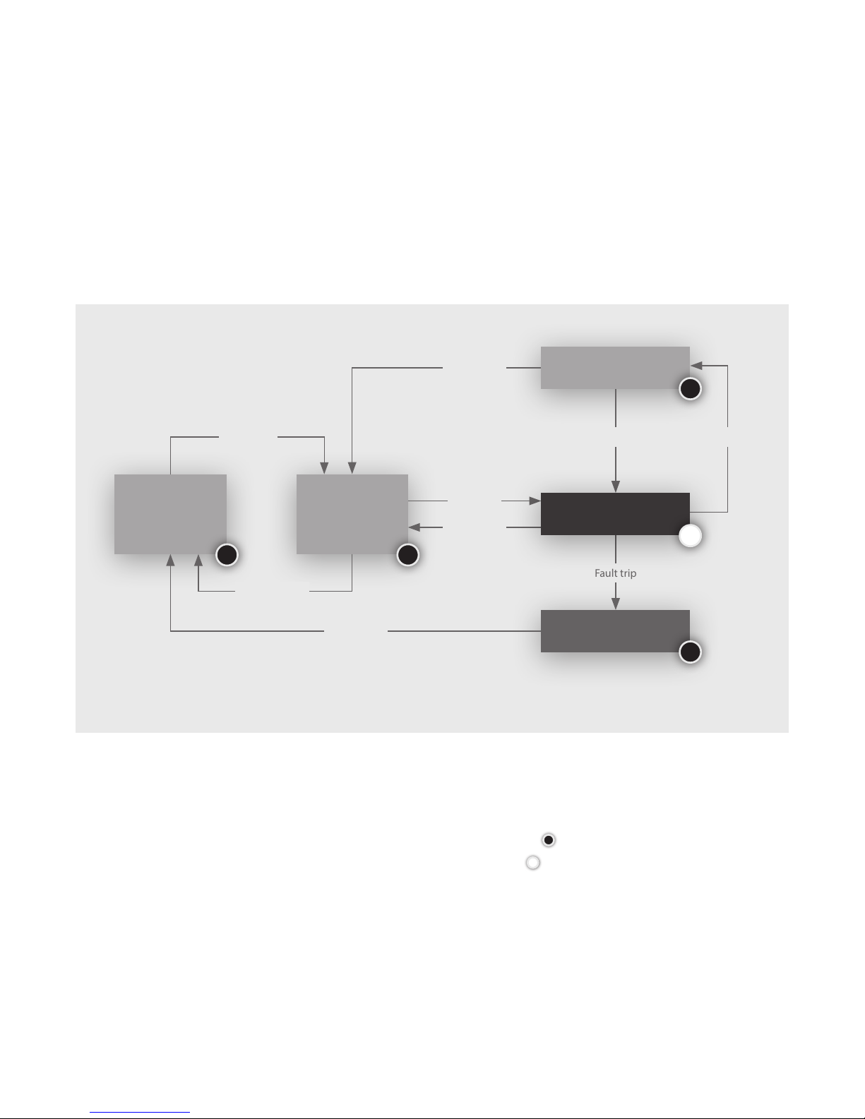
Fault state
If the parameters of the FCM-802/804 leave the normal operational range then a fault
is triggered. When a fault has been triggered the controller will latch. Toclear the
fault, the controller needs to be turned o via the Enable signal. For reset instructions
see Section 9.
Operation of FCM-802/8048

15
Number 10009655. A1
Procedure to reset the fault
If the FCM-802/804 has a fault it will disconnect the internal DC-DC converter and
stop providing power. To reset a fault, follow the procedure below:
The safety case of the overall installation must consider the fault condition of the fuel
cell as part of its analysis of the full function of the system.
9.1
Faults9
Note:
10.1 Mechanical mounting points
The FCM-802/804 must be installed as a standard 19" rack unit. This should then be
mounted on a at surface with four retaining points, these must be tightened to a
torque not exceeding 25Nm. When installing the FCM, inspect it and do not install if
there is visible damage to the unit. Any surfaces in contact with the FCM must not be
above +50°C. The FCM is 473mm deep (+45mm for the connection terminals). Allow at
least 50mm to the rear of the FCM for the cables/pipes to run in. It is recommended to
mount on a shelf with front and rear access for maintenance activity, as shown below:
Installation and set up10
448
75
146 302
483
· Check that the load is disconnected
· Switch the Enable signal to ‘O’
· Wait for ve seconds
· Return the Enable signal to ‘On’
· Set the Run signal to ‘On’
· Return the load to required setting

16 Installation and set up10
10.2
10.3
10.4
10.5
Note:
Mechanical protection and covers
The FCM-802/804 must be mounted with protection from weather and the elements.
The FCM-802/804 has been designed to comply with IP20 rating, it must be mounted
within an enclosure which is at least IP24 rated if used outside.
The covers of the unit must not be removed by unauthorised personnel. Theunit contains
live electrical components which could be hazardous, even when not operating. The covers
and the installation must protect the FCM-802/804 from precipitation and vegetation
ingress. The placement of the covers must consider the need for maintenance.
Do not remove the lid.
Do not remove terminal cover during operation.
Mechanical connection to the power terminals
It is important to use the correct procedure to connect the power terminals.
Incorrectprocedure could damage the unit if excessive torque is used. Excessiveload
may distort the internal busbars.
During Electrical maintenance/installation the FCM must be o and the load side
battery or external power supply must be made safe.
1 Two spanners (13mm).
2 One to hold rst nut to prevent it from rotating.
Note: There is a lock nut at the back holding the stud in place, which must not
beadjusted.
3 The other to tighten the second nut to secure cable/conductor terminal against
rstnut.
Mechanical connection to the Ground terminal
As standard the FCM 802/804 is provided negatively earthed. Positive earth version is
available as a factory congurable feature. The Ground terminal is located between the
two power terminals and should be used to earth the unit. The cable should be sized
to provide protection to the unit during operation and in foreseeable fault conditions.
Vibration and shock loads
The mounting of the FCM-802/804 must ensure that it is not exposed to shock or
vibration loads. Ensure that the FCM-802/804 is stationary while it is operating.
If the FCM has been stressed due to vibration or shock, return to Intelligent Energy
forinvestigation.
Warning:
Warning:
Warning:

17
Number 10009655. A1
Installation and set up10
Air supply and ventilation
The FCM-802/804 requires a free supply of clean air to deliver power output.
The unit will require up to 16 Sm3/min of unrestricted air ow. The operator
must consider the air ow required for the environmental conditions expected.
Theenclosure must not unduly restrict the air ow. The covers must be designed
such that the exhaust gas cannot be recirculated into the air inlet.
As part of the design, the main air ow is also used to manage the risk of a hydrogen
build-up. The hydrogen purge gas is routed into the air ow such that it is diluted
to below the low ammability limit at the point of exit from the unit; therefore, the
installer must take care not to restrict the exhaust stream. Also, this gas stream will
contain hydrogen, this is at a concentration where it is not ammable. However, the
air exhaust design must consider the hydrogen risk.
The FCM-802/804 must be provided with free venting air in the range of +5 to+40°C,
it must not be operated outside this range. The installation of the FCM 802/804 must
be considerate of other equipment near FCM 802/804 may elevate the local ambient
temperature during their operation. A local increase of ambient temperature may
aect the performance of the fuel cell. Do not use if the air has contaminants such as
smoke, volatile organics or corrosive chemicals present.
Hot air that is generated by other equipment within 0.6m of the inlet of the
FCM802/804 must be treated with care and should be limited to 5% of expected
operating power of the FCM 802/804 in order to limit the ingestion of hot air.
The FCM802/804 consumes oxygen as it operates, therefore the minimum air
ventilation requirement must be observed at all times to ensure safety of personnel
in the room:
· Rooms of less than 5m3must have a permanent vent area of 100cm2
· Rooms between 5 and 10m3must have a permanent vent area of 50cm2
· Rooms greater than 10m3do not require a permanent vent
The above is applicable only if openable windows (or equivalents such as grilles
or louvre panels) are also present. Extraction must be provided in cases where the
above does not apply. This covers internal rooms without windows. If the extraction
is adjacent to the fuel cell system the rate must be at least 30l/s. If the extraction is
elsewhere in the room the rate must be at least 60l/s.
10.6
Warning:

18 Installation and set up10
10.8 Hydrogen fuel physical requirements
The FCM-802/804 requires regulated fuel pressure to feed hydrogen into the cell.
Theinlet pressure for operation must be:
500mbar.g to 800mbar.g
The FCM-802/804 will consume less than 70g/kWh at rated power. This is equivalent
to 34sl/min (FCM-802) and 56sl/min (FCM-804) at rated power. It must be noted that
the ow will spike high during hydrogen purges, which, if poorly regulated, can lead
to a low pressure fault of the FCM.
It is required that the external system has an automatic shut-o valve as part of the
hydrogen feed line. This allows the hydrogen to be isolated at source if required.
Hydrogen Connection
Hydrogen connection
The FCM-802/804 requires hydrogen to fuel the electro-chemical reaction.
Connection of the hydrogen fuel will be at the rear of the module. The connection
type is a female G1/8 parallel BSP thread with a face seal, this must be connected
via an appropriate mating connector.
At installation the external hydrogen pipework must be bled of air or inert gas before
operation. Thehydrogen pipework must be checked periodically for leaks.
10.7

19
Number 10009655. A1
Fault Cause Action
No power from the
module
No command to start Verify that the module is in Enable and Run modes
(see section Connections)
Hydrogen leak See . Check for fuel leak
Incorrect hydrogen pressure See . Fuel check procedure
No power provided See . Electrical system check procedure
Fuel cell is over temperature See . Stack temperature check procedure
Maintenance procedures11
11.1
11. 2
12.1
User maintenance
The user can perform the following maintenance on the FCM-802/804:
· Monthly lter inspection
· Filter change
· Troubleshooting (see below)
Not performing these basic checks will reduce unit eciency. For all other
maintenance tasks, contact Intelligent Energy Ltd.
Contact Intelligent Energy Product Support Team
In the event of a fault with the FCM-802/804, please contact the Intelligent Energy
Product Support Team. Either contact your local representative or email:
servicing@intelligent-energy.com
Please have the part number of your product and the serial number (on the
nameplate). The part numbers are:
802: 10004360
804: 10004361
Trouble-shooting guide12
Possible causes of faults

20
Remove sources of ignition
Remove electrical load
Set FCM to “O” and “Disabled”
Is fault repeated?
Restart FCM
Verify hydrogen source is at an
output pressure within specication
(application specic)
Contact
IEProductSupportTeam
Return FCM to operation.
Inform IEProductSupport
of issue
Can the leak source be
identied?
Have a gas trained person
repair or replace faulty
component(s)
Isolate hydrogen source,
contact IE Product
Support Team urgently
Have a gas trained person conduct
pressure decay test on external
hydrogen supply system
Isolate hydrogen source, contact
IEProductSupportTeam
yes
yes
yes
pressure stable
no
no
no
pressure
dropping
Trouble-shooting guide12
12.2 Check for fuel leak
This manual suits for next models
1
Table of contents
Other Intelligent Energy Portable Generator manuals
Popular Portable Generator manuals by other brands

National Instruments
National Instruments NI 6.6 GHz MIMO Getting started guide

Unipower
Unipower Sageon III product manual

Briggs & Stratton
Briggs & Stratton 40297 Illustrated parts list

Sportsman
Sportsman GEN4000 Step-By-Step Quick Start Guide

Snap-On
Snap-On 5750 instruction manual

Bluetti
Bluetti AC300 How to connect

Lincoln Electric
Lincoln Electric NERTAMATIC 450 Instructions for use

PowerBoss
PowerBoss 30542 Operator's manual

REXROTH
REXROTH CytroPac operating instructions

Kimo
Kimo GP 500 Series user manual

Black Max
Black Max BM905511 Operator's manual

MULTIQUIP
MULTIQUIP Power WHISPERWATT DCA-400SSK Parts and operation manual