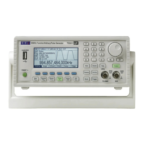
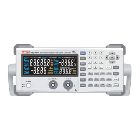
TTI TG1006 User manual

TG1006
10MHz DDS Function Generator
SERVICEMANUAL

2
Specifications
Specifications apply at 18°- 28°C after one hour warm-up, at maximum output into 50Ω.
WAVEFORMS
Standard waveforms of Sine, Square, Triangle and DC.
Sine
Range:
1mHz to 10MHz.
Resolution:
1mHz or 6 digits.
Accuracy:
10 ppm for 1 year; ± 1mHz below 0.2Hz.
Temperature Stability:
Typically <1 ppm/ºC outside 18° to 28°C.
Output Level:
1mV to 10Vp−p into 50Ω.
Harmonic Distortion: <0.3% THD to 20kHz (typically 0.1%).
<–45dBc to 300kHz.
<−30dBc to 10MHz (typically <−35dBc).
Non−harmonic Spurii:
<–55dBc to 1MHz, <–55dBc + 6dB/octave 1MHz to 10MHz.
Square
Range:
1mHz to 10MHz.
Resolution:
1mHz or 6 digits.
Symmetry Control:
20% to 80%, 1mHz to 10MHz.
Accuracy:
10 ppm for 1 year; ± 1mHz below 0.2Hz.
Output Level:
1mV to 10Vp−p into 50Ω.
Rise and Fall Times:
<25ns.
Aberrations:
<5% + 2mV.
Triangle
Range:
1mHz to 1 MHz.
Resolution:
1mHz or 6 digits.
Accuracy:
10 ppm for 1 year; ± 1mHz below 0.2Hz.
Output Level:
1mV to 10Vp−p into 50Ω.
Linearity Error:
<0.5% to 100 kHz.
OPERATING MODES
Continuous
Continuous cycles of the selected waveform are output at the programmed frequency.
Sweep
Carrier Waveforms:
All
Sweep Mode:
Manual, linear or logarithmic, single or continuous.
Sweep Width: From 0.1Hz to 10MHz in one range. Phase continuous. Independent
setting of the start and stop frequency.
Sweep Time:
100ms to 999.99s (10ms resolution).
Sweep SYNC:
Start of sweep trigger available from SYNC output.
Sweep Trigger Source: The sweep may be free run or a single sweep may be triggered from the
front panel MAN TRIG key.
Manual Sweep Mode: An analogue control can be used to set the generator to any intermediate
frequency between the Start and Stop frequencies.

3
Amplitude Modulation
Carrier Frequency:
From 1mHz to 10MHz.
Carrier Waveforms:
All.
Modulation Frequency:
400Hz internal. DC to 20kHz external.
External Modulation:
AM/COUNT IN socket.
Frequency Shift Keying (FSK)
Phase coherent switching between two selected frequencies at a rate defined by the switching
signal source.
Carrier frequency:
From 0.1Hz to 10MHz.
Carrier waveforms:
All.
Switch repetition rate:
DC to 10kHz (internal trigger).
Switching signal source:
Manual (front panel MAN TRIG key) or internal trigger generator.
Frequency List
Step through up to 10 stored frequencies.
Carrier Waveforms:
All.
Frequency List:
Up to 10 frequencies from 1mHz to 10MHz.
Switching Source:
Manual from front panel MAN TRIG key.
OUTPUTS
Main Outputs
Output Impedance:
50Ωand 600Ω (not independent).
Amplitude: 2mV to 20Vpk-pk open circuit, (1mV to 10V pk-pk into 50Ω/600Ω) in four
switch selectable ranges with 20dB vernier control within each range.
Amplitude can be displayed in Vpk-pk or Vrms.
Attenuator:
0, -20dB, -40dB, or -60dB.
Amplitude Flatness:
±0.2dB to 500kHz; ±2dB to 10MHz.
DC Offset Range: ±10V. DC offset plus signal peak limited to ±10V from 50Ω/600Ω; CLIP
shows in display when offset plus signal peak exceeds ±10V. DC offset
plus waveform attenuated proportionally by the attenuator.
Resolution:
3 digits for both Amplitude and DC Offset.
SYNC Out
Automatically selected to be either Waveform Sync or Sweep Sync.
Waveform Sync: A square wave at the main waveform frequency. Symmetry is 50% for
sine and triangle waves at MAIN OUT; for square waves symmetry is
the same as that of the waveform at MAIN OUT.
Sweep Sync: Outputs a trigger signal at the start of sweep to synchronize an
oscilloscope.
Output Signal Level:
Output impedance 50Ω nominal. Logic levels of <0.8V & >3V.
INPUTS
AM In
The AM/COUNT IN socket is set to AM input when EXT AM is selected.
Input Impedance:
40kΩ.
Input Sensitivity:
Approximately 2V peak-peak for 100% modulation.
Maximum Allowable
Input Voltage: ±10V.

4
Count In
The AM/COUNT IN socket is set to external frequency measurement when EXT COUNT is
selected.
Input Impedance:
1MΩ//20pF.
Input Sensitivity:
50mVrms (sinewave).
Maximum Allowable
Input Voltage: 30Vdc/30Vrms to 50Hz/60Hz with respect to ground
, reducing to
1Vrms above 1MHz.
DISPLAY FUNCTIONS
The LCD shows generator frequency setting at a resolution of 4 digits simultaneously with output
amplitude/offset, together with various status annunciators. Alternatively, the generator
frequency setting can be displayed independently of amplitude/offset to a resolution of 6 digits.
The LCD also functions as the external frequency measurement display with up to 7 digits of
resolution.
Internal Measurement Accuracy
Amplitude: Display shows peak-to-peak amplitude or rms value. Display corrected
for attenuator setting and waveform type. 3-digit resolution, accuracy
typically ±5% of range full scale.
DC Offset: 3-digit resolution; accuracy typically ±2% of setting ±1 digit. Display
corrected for attenuator setting.
External Frequency Measurement
Frequency Range:
3Hz to >120MHz.
Frequency Resolutuion:
Up to 7 digits displayed.
Input Sensitivity:
Better than 50mVrms (sinewave).
Measurement Time:
Automatic.
Accuracy:
±1 digit ± timebase accuracy.
Timebase Accuracy: <±5ppm initial error; <± 5 ppm/year ageing rate; typically less than
1ppm/°C.
GENERAL
Display:
LCD.
Data Entry: Keyboard selection of mode; value entry direct by numeric keys or
by rotary control.
Stored Settings: Up to 10 output frequencies may be stored and recalled from non-
volatile memory.
Size:
260(W) x 88(H) x 235(D)
Weight:
1.45kg. (3.2lb.)
Power: 110-120V AC or 220V-240V AC ±10%, 50/60Hz,
adjustable internally; 35VA max. Installation Category II.
Operating Range:
+5°C to 40°C, 20-80% RH.
Storage Range:
-20°C to + 60°C.
Environmental:
Indoor use at altitudes up to 2000m, Pollution Degree 2.
Safety & EMC:
Complies with EN61010-1 & EN61326.

5
Safety
This instrument is Safety Class I according to IEC classification and has been designed to meet
the requirements of EN61010-1 (Safety Requirements for Electrical Equipment for Measurement,
Control and Laboratory Use). It is an Installation Category II instrument intended for operation
from a normal single phase supply.
This instrument has been tested in accordance with EN61010-1 and has been supplied in a safe
condition. This instruction manual contains some information and warnings which have to be
followed by the user to ensure safe operation and to retain the instrument in a safe condition.
This instrument has been designed for indoor use in a Pollution Degree 2 environment in the
temperature range 5°C to 40°C, 20% - 80% RH (non-condensing). It may occasionally be
subjected to temperatures between +5°C and –10°C without degradation of its safety. Do not
operate while condensation is present.
Use of this instrument in a manner not specified by these instructions may impair the safety
protection provided. Do not operate the instrument outside its rated supply voltages or
environmental range.
WARNING! THIS INSTRUMENT MUST BE EARTHED
Any interruption of the mains earth conductor inside or outside the instrument will make the
instrument dangerous. Intentional interruption is prohibited. The protective action must not be
negated by the use of an extension cord without a protective conductor.
When the instrument is connected to its supply, terminals may be live and opening the covers or
removal of parts (except those to which access can be gained by hand) is likely to expose live
parts. The apparatus shall be disconnected from all voltage sources before it is opened for any
adjustment, replacement, maintenance or repair.
Any adjustment, maintenance and repair of the opened instrument under voltage shall be
avoided as far as possible and, if inevitable, shall be carried out only by a skilled person who is
aware of the hazard involved.
If the instrument is clearly defective, has been subject to mechanical damage, excessive
moisture or chemical corrosion the safety protection may be impaired and the apparatus should
be withdrawn from use and returned for checking and repair.
Make sure that only fuses with the required rated current and of the specified type are used for
replacement. The use of makeshift fuses and the short-circuiting of fuse holders is prohibited.
Do not wet the instrument when cleaning it.
The following symbols are used on the instrument and in this manual:-
Caution - refer to the accompanying documentation, incorrect operation
may damage the instrument.
terminal connected to chassis ground.
alternating current.

6
Installation
Mains Operating Voltage
The operating voltage of the instrument is shown on the rear panel. Should it be necessary to
change the operating voltage from 230V to 115V or vice-versa, proceed as follows:
1. Disconnect the instrument from all voltage sources.
2. Unclip the front bezel by gently pulling the centre of each long edge up and forward.
The case halves are held together by 4 plastic push-rivets. Use the blade of a small screwdriver
in the slot beside each rivet to first ease out the rivet head and then fully remove the rivet body,
see Figs (a) & (b) at the end of the ‘Dismantling the Instrument ‘ paragraph in the General section
that follows. Separate the case halves.
3. Remove the 6 screws securing the main pcb to the case upper and lift the pcb free,
complete with front and rear panels still connected. No further dismantling is required to access
the links that require changing, see (4.)
4. Change the appropriate zero-ohm links beside the transformer on the pcb:
Link LK2 only for 230V operation
Link LK1 and LK3 only for 115V operation
5. Refit the pcb to the case upper, ensuring all connections (especially safety earth) are
remade as before, and refit the case lower.
6. To comply with safety standard requirements the operating voltage marked on the rear
panel must be changed to clearly show the new voltage setting.
7. Change the fuse to suit the new operating voltage, see below.
Fuse The correct time-lag fuse must be fitted for the selected operating voltage.
For 230V operation use 125mA (T) 250V HBC.
For 115V operation use 250mA (T) 250V HBC.
Make sure that only fuses with the required rated current and of the specified type are used for
replacement. The use of makeshift fuses and the short-circuiting of fuse holders are prohibited.
Mains Lead
Connect the instrument to the AC supply using the mains lead provided. Should a mains plug be
required for a different mains outlet socket, a suitably rated and approved mains lead set should
be used which is fitted with the required wall plug and an IEC60320 C13 connector for the
instrument end. To determine the minimum current rating of the lead-set for the intended AC
supply, refer to the power rating information on the equipment or in the Specification.
WARNING! THIS INSTRUMENT MUST BE EARTHED
Any interruption of the mains earth conductor inside or outside the instrument will make the
instrument dangerous. Intentional interruption is prohibited.

7
General
Service Handling Precautions
Service work or calibration should only be carried out by skilled engineers using high quality test
equipment. If the user is in any doubt as to his competence to carry out the work, the instrument
should be returned to the manufacturer or their agent overseas for the work to be carried out.
This simplified service guide only details the routine calibration procedure and the dismantling of
the instrument to PCB assembly level. If a PCB assembly is suspected as being faulty it should
be returned to the manufacturer or their agents overseas for repair or replacement. The Parts
List gives the part numbers of each PCB assembly, together with the mechanical parts and
fasteners that can be easily replaced by the user.
Dismantling the instrument
WARNING!
When the instrument is connected to its supply, terminals may be live and opening the covers or
removal of parts (except those to which access can be gained by hand) is likely to expose live
parts. The apparatus shall be disconnected from all voltage sources before it is opened for any
adjustment, replacement, maintenance or repair.
Any adjustment, maintenance and repair of the opened instrument under voltage shall be
avoided as far as possible and, if inevitable, shall be carried out only by a skilled person who is
aware of the hazard involved.
1. Disconnect the instrument from all voltage sources.
2. Unclip the front bezel by gently pulling the centre of each long edge up and forward.
The case halves are held together by 4 plastic push-rivets. Use the blade of a small
screwdriver to remove the rivets*. Place the instrument upside down on the bench and
separate the case halves by removing the case lower. Only the case lower need be
removed to gain access to all the adjustments necessary for calibration.
3. To remove the individual assemblies, firstly remove the screws securing the MAIN PCB to
the case upper and lift out the PCB with front and rear panels attached.
4. The front panel assembly may be removed as follows. Remove the nut on the front panel
metalwork securing the green/yellow safety earth wire to the front panel metalwork.
Disconnect the two 16-way ribbon cables from PJ1 and PJ2 on the MAIN PCB.
Disconnect the four 2-way connectors from PJ4, PJ7, PJ8, and PJ11 on the MAIN PCB.
Use a soldering iron to desolder the two cables from the MAIN OUT and SYNC output
BNCs. Finally locate the MAIN Board PCB Screen (which is fitted above the switchbank)
and remove the screw that connects the MAIN Board PCB screen to the Control PCB.
The front panel assembly can now be separated from the MAIN PCB; take care not to
damage the switchbank whilst the front panel assembly is lifted clear.
5. To remove the CONTROL PCB from the front panel, first, with the aid of a soldering iron
desolder the wire that connects the AM/COUNT IN BNC to the CONTROL PCB. The wire
must be desoldered from the CONTROL PCB not the BNC; the wire can then be
straightened perpendicular to the CONTROL PCB allowing for simple disassembly and
reassembly. Remove all of the knobs from the front panel (including rotary encoder, AM
DEPTH, SYMMETRY, OFFSET and AMPLITUDE). Remove the seven screws securing
the CONTROL PCB to the front panel metalwork. Carefully lift off the CONTROL PCB
ensuring that the front panel metalwork is kept level and facing downwards to prevent the
loss of unsecured keycaps.

8
6. The MAIN PCB may be removed as follows. With the case and front panel assembly
removed, the MAIN PCB is left connected to the rear panel metalwork. This can be
separated by removing the nut that secures the green/yellow safety earth cable to the
rear panel.
7. Reassemble in the reverse order. Take care when reassembling the CONTROL PCB with
the front panel metalwork to ensure that all of the keycaps are correctly aligned.
* The snap-lock rivets are removed as follows:
First, ease out the head of the rivet using a fine
screwdriver blade under the edge of the head
(Fig.a). With the rivet head fully out, the body
of the rivet can now be eased out with the
screwdri
ver blade and removed completely
(Fig.b). To re-assemble, fully re-insert the body
of the rivet then push in the head to lock it.

9
Calibration
Equipment Required
Oscilloscope
4.5 digit battery powered multimeter
Reciprocal counting Frequency Meter
Only the case lower need be removed to gain access to all adjustments.
Allow 1 hour warm-up before commencing. For best results, use the following procedure.
1. Power Supply
+ 15V ± 20mV (adjust VR32) - 15V ± 20mV (adjust VR29)
+ 5V ± 0.25V - 5V ± 0.25V
+ 3.3V ± 0.1V
+1.8V ± 0.05V
2. Offset Nulling
Set instrument to 1MHz, sinewave, ensure the DC offset control is at its centre detent.
Connect DVM to TP1 and adjust VR7 for <1mV.
Connect DVM to main out, release all function buttons (DC) and adjust VR16 for <5mV
3. Level Calibration
Set instrument to 1MHz, sinewave, amplitude to maximum (20Vpk-pk).
Adjust VR6 for 20 Vpk-pk at the main output
Set instrument to squarewave
Adjust VR9 for 20V pk-pk at the main output
4. Waveform Symmetry
Set instrument to 1kHz, squarewave; ensure the Symmetry control is at its centre detent.
Adjust VR5 for a 50:50 mark space ratio using the oscilloscope x10 X-multiplier (to increase
resolution) and the trigger slope switch.
5. Frequency Calibration
Connect frequency counter to SYNC output; adjust VC1 to within ±1ppm.
Alternatively select external count and apply a frequency standard to AM/COUNT IN, adjust VC1
for correct reading ±1ppm.
6. AM
Set instrument to 300kHz, sinewave, modulation to minimum, amplitude to maximum (20Vpk-pk),
Select INT AM and enable, check output drops to half (10Vpk-pk); adjusted by VR18
Modulation to maximum, adjust VR17 for 100% modulation.
Release all 3 function buttons (DC), increase the oscilloscope gain, and adjust VR19 for
minimum output of the 400Hz modulation source.
Adjust VR26 for 0V ±50mV output.

10
7. Meter Calibration
Select Vpk-pk display with the PK-PK/RMS key, set instrument to 1kHz, squarewave.
Adjust the amplitude control to give 16Vpk-pk (8Vpk-pk into 50Ohm) at the output, and then
adjust VR27 on the control board for 16.0Vpk-pk on the display.
Select OFFSET display, release all 3 function buttons (DC), amplitude to minimum, offset control
at centre detent, and connect DVM to the main output. Adjust VR15 to match the generator’s
meter to DVM meter.
Set offset control to maximum (fully clockwise), adjust VR25 to match the generator’s meter to
DVM meter, ± 1%.

11
Parts List
Part Number
Description
Position
PCB ASSEMBLIES
44913-0500
PCB ASSEMBLEY - MAIN - TG1006
44913-0510
PCB ASSEMBLEY - CONTROL - TG1006
MECHANICAL ITEMS
20010-0258
RIVT SNAPLOK 3.6Dx2.7-3.6L GREY
FOR CASE
20010-0259
RIVET, SCREW TYPE
FOR FEET
20662-0590
FOOT - BLACK RBS-1 - S/ADHESIVE
22040-0030
FERRITE SLEEVE 9/16/17L
50Ohm CABLE (1 TURN),
TTL/CMOS CABLE (1 TURN)
22225-0800
SWITCHBANK X 5 - TG1006
22588-0004
BNC BULKHEAD SOCKET 50Ohm
23202-1549
RES 549RF W60 MF 50PPM
31547-1230
EARTH CONTACT STRIP - TG1006
FROM TOP SCREEN PCB
TO FRONT PANEL
31711-0210
BEZEL - BENCH CASE 2 - L/GREY
33143-0310
FOOT PLAIN (ROUND) BENCH CASE 2
33143-0320
FOOT BAIL HOUSING BENCH CASE 2
33143-0330
FOOT TILT BAIL BENCH CASE 2
33331-2050
FRONT PANEL - TG1006
33331-2060
OVERLAY – FRONT PANEL TG1006
33331-8240
REAR PANEL
33536-4380
CASE UPPER BENCHCASE 2 L/GREY
33536-4390
CASE LOWER BENCHCASE 2 L/GREY
35555-5740
PCB - SCREEN - TG1006
MAIN BOARD SCREEN PCBs
37113-0263
BUTTON 5.6X6.6 SWITCHBANK GREY3
37113-0413
BUTTON 5.6X5.6mm GREY3
37113-2033
KEYCAP 8X3MM GREY3
37113-2070
KEYCAP 8X3MM SOFT KEY BLUE
SHIFT KEY
37151-0493
KNOB 12.5MM D-SHAFT GREY3
37151-0570
KNOB ENCODER 26MM GREY3
ENCODER
43171-2910
CONNECTOR ASSY 16W 115mm TG1006
43171-2920
CABLE ASSY MAIN/CTL TG1006 150mm
43171-2921
CABLE ASSY MAIN/CTL TG1006 190mm
43171-2930
CABLE ASSY CTL TG1006 150mm
43187-2070
WIRE SET CUT TG1006
46912-5170
FIXINGS & FASTENERS TG1006
48591-1250
INSTRUCTION BOOK TG1006

Thurlby Thandar Instruments
Ltd
.
Glebe Road • Huntingdon • Cambridgeshire • PE29 7DR • England (United
K
ingdom
)
Telephone: +44 (0)1480 412451 • Fax: +44 (0)1480 450409
International web site:
www
.aimtti.com • UK web site:
www
.aimtti.co.uk
Email: info@aimtti.com
Aim Instruments and Thurlby Thandar Instruments Book Part No. 48591-1270Issue 1
Table of contents
Other TTI Portable Generator manuals
Popular Portable Generator manuals by other brands
Generac Power Systems
Generac Power Systems 8 - 20kW Air-cooled Automatic Standby... owner's manual

KEHUI
KEHUI T-305E user manual
EWM
EWM Titan XQ 400 puls D operating instructions

Powermate
Powermate PM0601100 instructions
Wacker Neuson
Wacker Neuson GP 4000 Operator's manual
evertz
evertz S621 instruction manual


