Intelligent Home 2-Easy DT601 Fingerprint User manual

Surface mount Flush mount
2-Easy
2-wire series
Door Station Mod. DT601 Fingerprint
www.intelligenthomeonline.com

Side View Wall box for Flush mounting
Fingerprint
window
Rain Cover for Surface installation
Surface mount version 93 mm
182 mm
30 mm
Flush mount version
220 mm
120 mm
Camera Lens
Speaker
Call Button
Microphone
Night Light
Screws for panel
mounting
Camera Lens
Speaker
LED 2
Call Button
Microphone
Night Light
LED 1
KEY 2 LocationKEY 1 Location
LED 2
LED 1
KEY 2 LocationKEY 1 Location
Fingerprint
window
Parts and Functions
-1-
Introduction
This door station is equipped with a high resolution colour ARS camera sensor with resolution 500TV Lines,
with a wide angle of view 105 degrees. White LEDs enable the door station to work efficiently at night. The
door station facia is made of stainless steel. There are both surface mount and flush mount versions.
Door station is equipped with built-in Fingerprint Reader for up to 200 users.
Door station can be connected to one electric gate/lock by default or to two locks with an additional DT-RLC
Lock Interface
Key1 and Key2 location (see drawing above)
Key1 and Key2 are used for programming, so it is important to understand how to activate them
because they are invisible and located on the bottom edge of the Fingerprint cover. For security
purposes, they are not marked by a visible mark or symbol. They only can be activated in first 10
seconds after the door station is powered up. To activate, place your left thumb on the surface of the
cover to activate Key1 (use your right thumb to activate Key2). Make sure that a thumb is resting flat on
the surface

Terminal Descriptions
1 2 3
Lock Control Jumper
BUS
PL
S+ S-
Main Connect Port
•Lock Control Jumper: To program electric lock type
• Main Connect Port: To connect the bus line and the electric lock
• BUS: Connect to the bus line, no polarity
• PL: Additional power supply for the lock input, connect to the power positive (power +)
• S+:Lock power (+) output
• S-: Lock power (-) output

Door Station Mounting
1 2
43
Drill holes in the wall to match the size of
screws and attach the rain cover to the wall
Attach the door station to the rain cover Secure with screws
Connect the cable
Surface Version Mounting
-2-
Surface mount version will be supplied with stainless steel rain/mounting bracket.
Flush mount version will be supplied with wall mounting box.
Please use drawings below for installation tips

Flush Version Mounting
1 2
43
Cut a hole in the wall to match the size of the
mounting box and install the wall box
Attach the door station to the mounting
box and secure with screws
Connect the cable
1- Monitor Kit Connection Diagram
BUS(IM) BUS(DS)
PC6
AC~
-
+
L1 L2 PL S+ S-
Doorbell Button
Switch
1 2 3
ON
DIPS
-3-

-4-
Electric Lock Connection
Electric lock can be powered from Door Station
if:
1. Electric lock is ‘Power-on-to-unlock’type
2. The lock is 12V, and holding current is less
than 250mA
3. lock control is not timed from Exit Button (EB)
The ‘Unlock Mode’Parameter would be 0
(default, no need extra programming)
EB
*
LOCK
BUS PL S+S-
Jumper position 2-3
1 2 3
LOCK
Take off the Jumper
POWER
SUPPLY
BUS PL S+S-
Automated Gates and Magnetic Locks
1. Connect low voltage box of the gate according the
diagram. Use power supply for magnetic lock
according lock specs
2. The inside relay contact is restricted to AC or DC
24V/1A
3. The jumper must be taken off
The ‘Unlock Mode’ parameter for ‘Power-on-to-unlock’
would be 0 (default, no need extra programming)
The ‘Unlock Mode’ parameter for ‘Power-off-to-unlock’
would be 1(needs extra programming via monitor)
‘Installer Setup’)

Unlock parameterssetting (via monitor)
-5-
Multiple Door Stations Connection
1# Camera2# Camera3# Camera4# Camera
L1 L2 PL S+ S-L1 L2 PL S+ S-L1 L2 PL S+ S-
L1 L2 PL S+ S-
ID Address:3 ID Address:2 ID Address:1 ID Address:0
100~240VAC
DBC4A
A B C D
OFF
ON
Impedance
switch
BUS(IM) BUS(DS)
PC6
AC~
Notes:
1. Door Station and Lock must be connected and powered up before programming
2. To find how to access ‘Installer Setup’ menu, refer to the monitor manual
3. New parameterswill be synced automatically
1.Touch icon on
main menu page
2.Touch UNLOCK
button and hold for 2s
3.A digital keypad will
be shown
About
Local Address 00.00
Video Standard AUTO
System Verson 00.01.00
Display Driver 1.0
Front 1.0
UI 1.0
INSTALLER SETUP 123
_

-6-
Multiple Monitors Connection via Daisy-chain
Door Station ID Address:0 (default)
BUS(IM) BUS(DS)
PC6
AC~
100~240VAC
Code=14Code=15 Code=0

Star Connection with DBC-4A distributor
Door Station ID Address:0 (default)
Code=0
OFF ON
OFF ON
DBC4A
A B C D
DBC4A
A B C D
Impedance
switch
Impedance
switch
100~240VAC
BUS(IM) BUS(DS)
PC6
AC~
Code=2
Code=1
Code=3
Code=12
Code=14
Code=13
Code=15
-7-

-8-
Door Station Address/ID Setup
1)Power-on
2) within 10 seconds Press and
hold "KEY2" for 3 seconds, to
enter Programming Mode
LED 1 Buzzer
beep,beep
(red,ashing)
Press and hold "KEY1" and
"KEY2" for 3 seconds at the
same time
LED 1 Buzzer
beep, beep
(off)
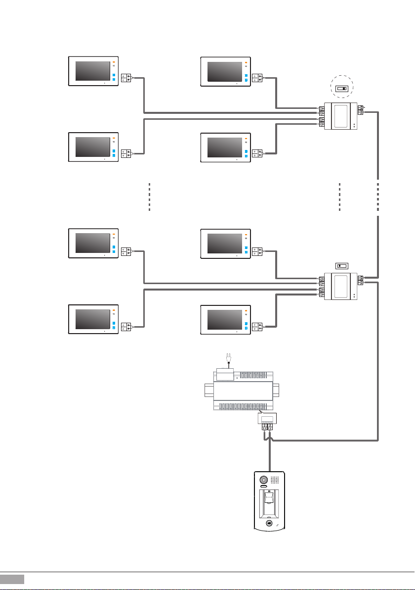
Up to 4 x Door Stations can be connected to one system. In case if multiple Door Stations connected,
they have to be assigned with unique Address/ID.
First Door Station Address/ID would be 0(default)
Second Door Station Address/ID would be 1
ThirdDoor Station Address/ID would be 2
Forth Door Station Address/ID would be 3
Followed by pressing the "KEY2"
button, each time you press
KEY2 to replace the ID;
Note:The ID will cycle between
ID0
ID1
ID2
ID3.
LED 1 Buzzer
beep one
(green,ash one)ID0:
beep twice
ID1:
beep 3 times
ID2:
beep 4 times
ID3:
(green,ash twice)
(green,ash 3 times)
(green,ash 4 times)
Note: any operation must be done within 10 seconds of door station powering up
Note: If there is no activity within 10seconds, system will exit Programming mode

-9-
1)Power-on
2) within 10 seconds Press and
hold "KEY2" for 3 seconds to
enter the Programming mode
LED 1 Buzzer
beep,beep
(red,ashing)
Press and hold "KEY1" for 3
seconds
LED 1 Buzzer
beep,beep
(off)
Press and hold "KEY2", time
count starts; release "KEY2" to
end. The time of pressing and
holding "KEY2" equal to
unlocking time. (Timing Unit: 1s)
LED 1 Buzzer
beep once
per second
(green,
flash once
per second)
Unlocking Time Settings
The unlocking time can be set to 1~30 seconds. The default is 1s
Note: any operation must be done within 10s of door station powered-up
Note: If there is no activity within 10 seconds, system will exit Programming mode

-10-
1)Power-on and within 10
seconds
2)Press and hold "KEY2" for 3
seconds, to enter the
Programming mode
LED 1 Buzzer
beep,beep
(red,ashing)
Press and hold "KEY2" for 3
seconds
LED 1 Buzzer
beep,beep
(off)
Door Station Ringtone Settings
There are three options of ringtone: [A]-One ringtone, [B]-Continuous ringtone, [C]-No ringtone.
The default is A- One ringtone
Followed by pressing the "KEY2"
button,each time you press KEY2
to replace the ringtone mode;
Note:The ringtone mode will cycle
between [A]
[B]
[C].
LED 1 Buzzer
beep one
[A]:
beep twice
[B]:
beep 3 times
[C]:
(green,ash one)
(green,ash twice)
(green,ash 3 times)
Note: any operation must be done within 10s of door station powered-up
Note: If there is no activity within 10seconds, system will exit Programming mode

-11-
Master Fingerprint Creation
1)Power-on and within 10 seconds
2)Press and hold "KEY1" for
3 seconds to enter Master
Fingerprint setting mode
LED 1 LED 2 Buzzer
beep,beep
(off) (off)
Touch nger in the ngerprint
window, get it identied first
time
LED 1 LED 2 Buzzer
beep+,beep
( green,
ash 3 times)
(off)Success:
(blue)
LED 1 LED 2 Buzzer
beep,beep,beep
( red,
ash 3 times)
(off)Failure:
(off)
Touch nger in the ngerprint
window again, get it identied
second time
LED 1 LED 2 Buzzer
beep+
( green,
ash 3 times)
(on)Success:
(red)
LED 1 LED 2 Buzzer
beep,beep,beep
( red,
ash 3 times)
(off)Failure:
(off)
If second identification was suc-
cesfull, the system will exit setting
mode and return to the standby.If
it fails, the system will return to the
operation of rst identied. Repeat
second identification once again.
Master Fingerprint enables you to register or delete user’s fingerprintsand program or change
parameters of programming i.e. unlocking time, ringtone and so on. The system can have
one only Master ngerprint
Note: any operation must be done within 10s of door station powered-up
Note: If there is no activity within 10 seconds, system will exit Programming mode

-12-
1)Power-on and within 10 seconds
2)Press and hold "KEY1" for
3 seconds to enter Programming
mode
LED 1 LED 2 Buzzer
beep,beep
(red) (off)
Present original Master
Fingerprint, Confirm Master
Fingerprint
LED 1 LED 2 Buzzer
beep,beep
(off)
Update Master Fingerprint
If the system already has registered Master Fingerprint, it can be change to a new Master Fingerprint.
Operation as follows:
Success: (off)
LED 1 LED 2 Buzzer
beep,beep,beep
( red,
ash 3 times)
(off)Failure:
(red)
Present new Master
Fingerprint, get it rst time
identied
LED 1 LED 2 Buzzer
beep+,beep
( green,
ash 3 times)
(off)Success:
(blue)
LED 1 LED 2 Buzzer
beep,beep,beep
( red,
ash 3 times)
(off)Failure:
(off)
Touch new Master Fingerprint,
get it second time identied
LED 1 LED 2 Buzzer
beep+
( green,
ash 3 times)
(on)Success:
(red)
LED 1 LED 2 Buzzer
beep,beep,beep
( red,
ash 3 times)
(off)Failure:
(off)
Note: After succsesful second identication the system will exit Programming mode and return to the standby.
When it failed, the system will return to the operation of rst identied
Note: any operation must be done within 10s of door station powered-up

-13-
Present Master Fingerprint in
standby mode to enter the state
of user ngerprints setting
LED 1 LED 2 Buzzer
beep,beep
(green) (off)
Add User’s Fingerprints
Present new ngerprint, get it
rst time identied
LED 1 LED 2 Buzzer
beep+,beep
( green,
ash 3 times)
Success:
(blue)
LED 1 LED 2 Buzzer
beep,beep,beep
( red,
ash 3 times)
Failure:
(off)
Present new ngerprint, get it
the second time identied
LED 1 LED 2 Buzzer
beep+
( green,
ash 3 times)
Success:
(off)
LED 1 LED 2 Buzzer
beep,beep,beep
( red,
ash 3 times)
Failure:
(off)
Note: After succsesful second identication the system will exit Programming mode and return to the
standby.When it fails, the system will return to the operation of rst identied
Note: any operation must be done within 10 seconds of the door station powering up
The system can store up to 200 user’s ngerprints.
User’s Fingerprints Registration
Press "KEY1"
LED 1 LED 2 Buzzer
beep,beep
(off) (ash slowly)
(ash
slowly)
(ash
slowly)
(ash
slowly)
(ash
slowly)

-14-
Present the Master Fingerprint in
standby mode to enter the
Programming mode
LED 1 LED 2 Buzzer
beep,beep
(green) (off)
Delete Specied User Fingerprint
Present the ngerprint you need
to delete
LED 1 LED 2 Buzzer
beep,beep
( green,
ash 3 times)
Success:
(off)
LED 1 LED 2 Buzzer
beep,beep,beep
( red,
ash 3 times)
Failure:
(off)
Press "KEY2"
LED 1 LED 2 Buzzer
beep,beep
(off) (ash quickly)
(ash
quickly)
(ash
quickly)
Note: If there is no activity within 10 seconds, system will exit Programming mode

-15-
Present Master Fingerprint in
standby mode to enter
Programming mode
LED 1 LED 2 Buzzer
beep+,beep
(green) (off)
7.3 Delete All User Fingerprints
Present Master Fingerprint to
delete all user ngerprints at
once
LED 1 LED 2 Buzzer
beep+
( green,
ash 3 times)
Success:
(red)
LED 1 LED 2 Buzzer
beep+,beep,beep
( red,
ash 3 times)
Failure:
(off)
Press and hold "KEY1" and
"KEY2" button at the same time
LED 1 LED 2 Buzzer
beep+,beep
(off) (double ash)
(on)
(double
ash)
Note: After successful second identication the system will exit Programming mode and return to
standby.Ifit fails, the system will return to the rst identication operation
Note: If there is no activity within 10 seconds, system will exit Programming mode

-16-
Precautions
9. Specications
•Please clean the unit with soft cotton cloth.Don't use organic impregnantsor chemical cleaning agents.
If necessary, please use a little pure water or dilute soapywater to clean the dust.
•The unit is weather resistant. However do not spray high pressure water on access control keypad
directly. Excessive moisture may cause problems with the unit.
•You must use the right adaptor which is supplied by the manufacture or approved by the manufacturer.
•High voltage spikes will destroy the product. Please get it serviced only by a trained and qualied
professional.
•Power Supply : DC 24V ;
•Power Consumption: Standby 34mA; Working status 158mA;
•Camera: Color ARS; 500 TV Lines;
•Lock Power supply: 12Vdc, 280mA(Internal Power);
•Mounting: Surface mount(DT601/FP)
Flush mount (DT601F/FP)
•Working temperature: -15ºC ~ +55ºC
•Wiring: 2 wires, no-polarity
•Dimension: 182(H)×93(W)×44(D)mm Surface version
220(H)×120(W)×50(D)mm Flush version

-17-
B
A
C
DBC4A
monitor
monitor
monitor
two or four monitors
BUS(IM) BUS(DS)
PC6
AC~
100~240VAC
Cables Requirements
This system transmits video and audio through the power cable. No Polarity connection.
Recommended cables: twisted pair, power-flex multi-cores (stranded), speaker cable, CAT5/CAT6
Minimum requirements 0.5mm cable up to 2mm (depends on distance)
When Monitor quantity < 20
Cable Usage A B C
Twisted cable 2x0.75 mm260 60 60
Twisted cable 2x1 mm2150 1500 1000
When Monitor quantity > 20
Cable Usage A B C
Twisted cable 2x1 mm270 70 70
Twisted cable 2x1.5 mm2100 100 100

-18-
WARRANTY CARD
NB Please keep this document safe, as it is proof of your Warranty
Your Video door system comes with a one year Manufacturers Warranty. When
used normally, the following services are offered:
The following actions will void the Warranty:
1. Damage to the device during installation
2. Damage to the device through misuse
3. Opening and/or disassembling the device
4. Attempting to force the device to perform functions for which it is not intended
5. Attaching the device to power supplies other than thoserecommended by the
manufacturer
Distributor for Warranty purposes:
Intelligent Home Online Ltd
62 Hartley Old Road
Purley, Surrey
CR8 4HJ
+44 (0)20 86170015
www.intelligenthomeonline.com
Product:_____________________________________________
Serial Number: ________________________________________
Invoice N: ____________________________________________
Purchase Date_________________________________________
Table of contents
Popular Accessories manuals by other brands

Comax
Comax CM-PIR03 Operation manual

Waterpik
Waterpik WP-440 instruction manual

Schulte
Schulte EVOline FlipTop Mounting instruction

TaoTronics
TaoTronics TT-AD007 user guide

DURAVANT
DURAVANT QC Conveyors PF51 Installation Manual, Operation & Maintenance Instructions

Miele
Miele SEB 234 - 2 operating instructions