11. Specications
• Power Supply: DC 10~12V (Powered by Monitors)
• Consumption: 150mA in working state (latch not included)
• Video Output: 75Ohm, 1Vp-p, CCIR standard (unless specied)
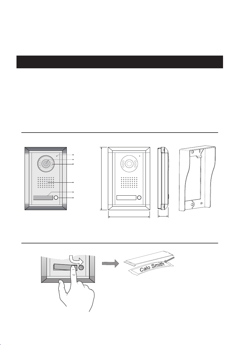
• Camera: 76 degree, CCD or CMOS camera with NightView-LED
• Working temperature: -10 ~ 40 degree
10. Connect a lock using the Monitor power only
9. Connect an electro-magnetic lock(power-OFF-to-open)
8. Connect an electron lock(power-ON-to-open)
Remove the JS/LK jumper on Monitor
Safety Type: Power-on-to-open
The lock consumption must not
greater than 12V 500mA.
Electronic lock
+
-
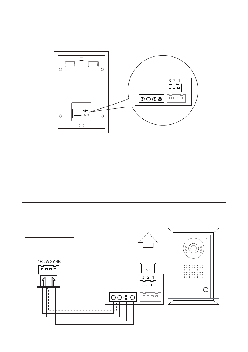
VT593
1R 2W 3Y 4B
The lock consumption must not
greater than DC 48V 1.5A.
Safety Type: Power-off-to-open
Adaptor
Electro
Magnetic
Lock
+
+
--
Keep the JS/LK jumper on Monitor
VT693
1R 2W 3Y 4B
Safety Type: Power-on-to-open
The lock consumption must not
greater than 48V 1.5A.
Electronic lock
Adaptor
+
+
--
Keep the JS/LK jumper on Monitor
VT593
1R 2W 3Y 4B
1. When using the power solely from the Monitor,
only the Power-on-to-unlock type electronic lock
can be supported. The rating of the lock must be
less than 12V 500mA.
2. Connect the 2 Black wire to the 1 Red wire
from Monitor, connect 1 Red wire to the lock (+),
connect 2 White wire from Monitor to the lock (-).
1. When connecting an electro-magnetic lock, an
external power supply is needed (not included with
this product).
2. The rating of the lock must be less than DC 48V
1.5A.
3. Connect the 2 Black wire to the power (+),
connect 3 White wire to lock (+), and connect the
power (-) to the lock (-).
1. When connecting an electric lock, an external
power supply is needed (not included).
2. The rating of the lock must be less than DC 48V
1.5A.
3. Connect the 2 Black wire to the power (+),
connect 1 Red wire to lock(+), and connect the
power (-) to the lock (-).
-4-