intellijel designs Plog User manual
Plog rev 1.0 MANUAL
1
Plog rev 1.0 MANUAL
1
The Intellijel Plog is a voltage controllable digital logic
device designed for musical applications. It is primar-
ily intended to create controllable patterns from gate/
pulse sources like clocks and sequencers.
It has many other applications other than to simply
mutate drum patterns. What you will use it for is up to
your imagination!
It contains four major blocks of logical operations.
These blocks are normalled in such a way that all the
blocks can be used together with minimal patching.
The Plog comprises two - triple input boolean logic
sections (with CV over type), a toggle ip op and a
data ip op.
The Toggle ip op can also be turned into a tap
tempo clock source.
The normals of the Plog can all be broken via the
switching jacks or in the case of theToggle input by a
jumper on the rear panel.
The Plog has been realized with a micro controller
that allows us to have features such as CV over logic
type and memory recall of initial logic state. The digi-
tal design of the Plog also means it is very shallow
behind the panel.
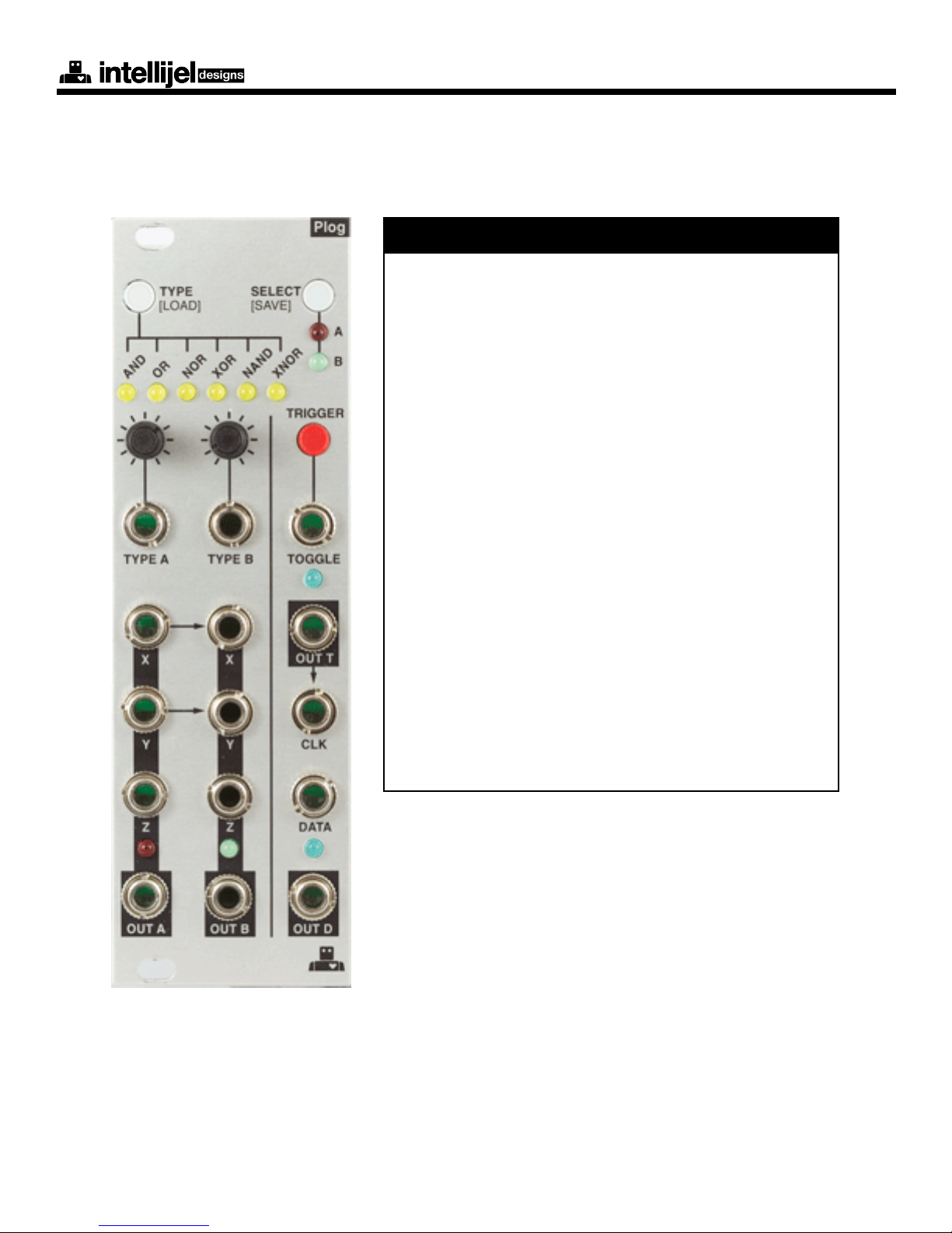
Overview

Plog rev 1.0 MANUAL
2
1 - TYPE (LOAD)
This button selects the logic type for the
selected channel, A or B. It also acts as
the starting point when under CV con-
trol. Press and hold this button for one
second to load the stored preset from
memory.
2 - These two mini knobs attenuate the
CV coming into their respective CV in-
puts labeled Type A and Type B.
3 - Type A/B bipolar CV input for logic
type of channel A/B. You will see the
logic type LEDs move when CV is pres-
ent and SELECT is on A/B.
4-XInput X for logic operator
5 - Y Input Y for logic operator
6-ZInput Z for logic operator.
This is a switching jack with Input Y nor-
malled to it unless patched.
The X and Y inputs for Logic block A are
normalled to the X and Y inputs of B.
7- OUT A /B is the output of the logic
operation.
8 - SELECT (SAVE)
Pressing this button selects between
logic A or B for the display of the yellow
Front Panel
LED logic type and the operation of the TYPE button. Pressing and holding this button for more than
one second will save the logic type selections into non-volatile memory.
9- TRIGGER button is normalled to the TOGGLE input below. When pressed it will send a trigger
to the toggle ip op. Press and hold on this button for one second and it will become a simple tap
tempo clk generator. Once in TAP MODE, start clicking the button in time with the tempo you would
like to set. To return to T-Flip-Flop mode simply hold the same button again for 1 second.
Plog rev 1.0 MANUAL
3
A - TOGGLE input to the toggle ip op. The TRIGGER button is normalled to this input with a
switching jack.
NOTE: There is a jumper on the back of the Plog module that connects the output of logic B to the
normalled input of T.
B - OUT T this is the output of the toggle ip-op. If in tap tempo mode this becomes the tempo
clock output (unipolar square pulses)
C - CLK clock input to the data ip-op. OUT T is normalled to here with a switching jack.
D - DATA data input to the data ip-op
E - OUT D output of the data ip op
NOTE: All of the logic and trigger inputs are expecting 0-5V signals (i.e. logic level pulses/gates/
clks). However the inputs all have negative and over voltage protection. Also each input employs
a comparator with a threshold of approximately 3V. This means you can still use non-square wave
signal sources as long as they exceed the comparator threshold (i.e. the positive excursion of a
triangle wave from a VCO/LFO).
The PLOG contains two - three input Boolean logic processing blocks. These are fundamental
building blocks of all logic systems and you are encouraged to check out some of the many excel-
lent tutorials available on the web.
Althought the logic blocks are three input, the third input (Input Z) is normalled to the second input
(input Y). This allows for a the three input devices to behave like two input logic devices if you only
use the X and Y inputs. Also the X and Y inputs of logic block B are normalled to the X and Y inputs
of logic block A. This creates the option to generate outputs from two logic blocks at the same time
with only one pair of inputs.
The truth tables for operating each of the logic blocks as a three input or two input device are in the
diagrams below. On this module a logic input of 0V or GND is the equivalent of a logic LOW or ‘0’
on the truth table.
An input of 5V is the equivalent of a logic HIGH or ‘1’on the truth table.
Front Panel - cont’d
Boolean Logic Blocks
Plog rev 1.0 MANUAL
4
X Y Z AND OR NOR XOR NAND XNOR
0 0 0 0 0 1 0 1 1
0 1 0 0 1 0 1 1 0
0 1 1 0 1 0 1 1 0
1 0 0 0 1 0 1 1 0
1 0 1 0 1 0 1 1 0
1 1 0 0 1 0 1 1 0
1 1 1 1 1 0 0 0 1
INPUTS
LOGIC OUTPUTS
X Y AND OR NOR XOR NAND XNOR
0 0 0 0 1 0 1 1
0 1 0 1 0 1 1 0
1 0 0 1 0 1 1 0
1 1 1 1 0 0 0 1
INPUTS
LOGIC OUTPUTS
Table 1: 3-input logic
Table 2: 3-input logic
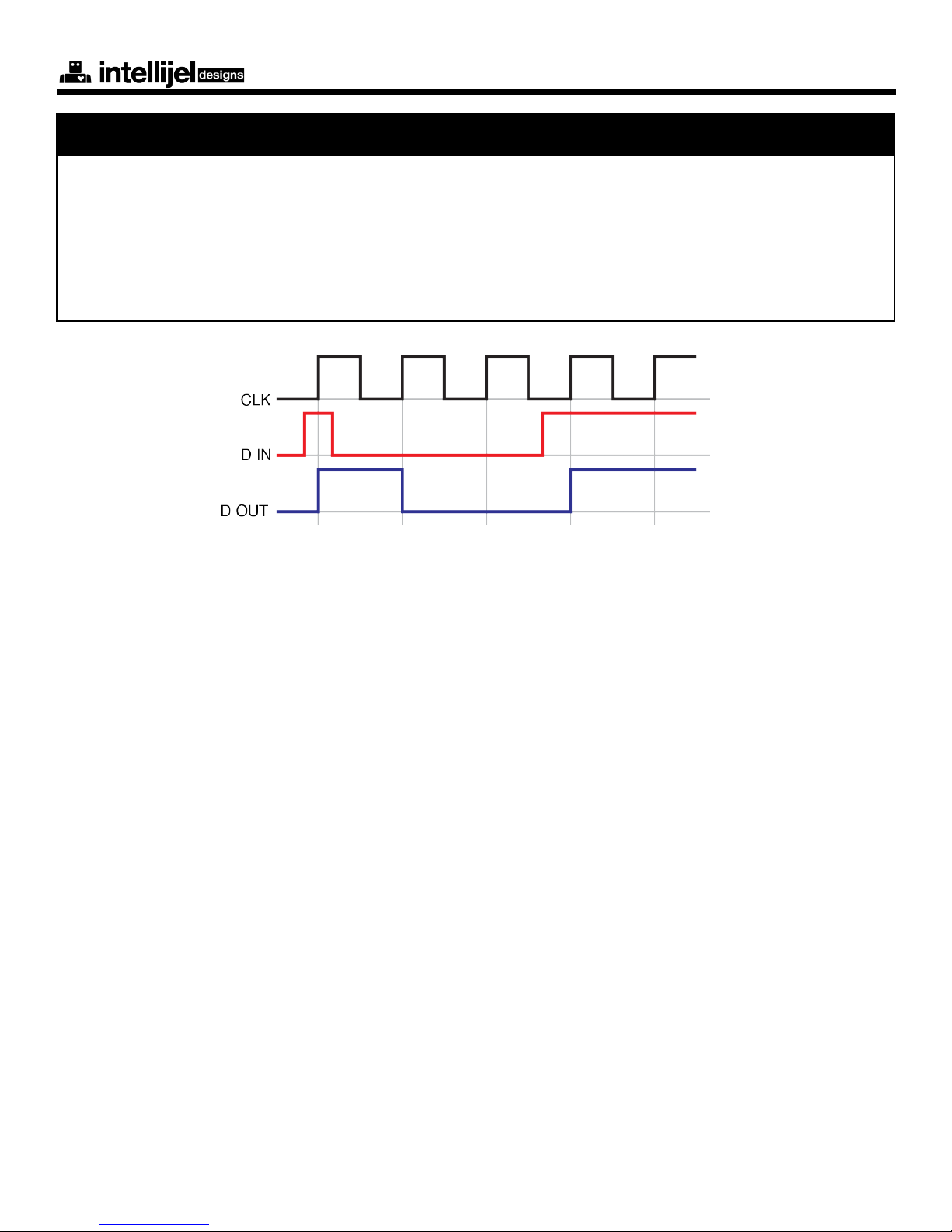
The Plog contains two types of Flip-ops: a Toggle (or a Latch) and a Data (or gated D latch). They
can be used to divide pulses, store binary data, create pendulum reset for sequencers etc.
By default the normals in the Plog set the Flip Flop section to be a divide by two and divide by
four. This acts as a clock divider of logic B without patching the inputs. If you patch a clock into the
Toggle input the OUT T and OUT D will divide the clock by two and four respectively.
Flip-op Logic Blocks
Plog rev 1.0 MANUAL
5
The D Flip-op output latches to whatever logic level the input is but only when the CLK signal
transitions from low to high.
The CLK input is also normalled (via the switching jack) the inverted output of the D Flipop. This
causes the D FlipFlop to function as a T Flip-op if nothing is patched into the CLK input.
The following diagram illustrates the relationship between the D Flip-op inputs and output.
Data (D) Flip-op

Plog rev 1.0 MANUAL
6
Example # 1: Real-time Quantizer Using AND Logic
Set A to AND and patch a random source of triggers into X.
Then patch a quantized source of triggers into Y.
Patch OUT A into a envelope generator.
Patch the envelope generator into something you want to modulate with quantized random enve-
lopes such as a VCA.
Using AND logic on a random source of triggers such as a square wave LFO.and a in synchronized
source of triggers (such as a 16th note pattern from a drum machine or sequencer) will create a
real time quantizer . This works because AND will go High when both the random trigger source
and the clock source are High. This means that as long as the random source goes high when the
16th note also goes high you will get a semi random sequence of 16ths. I nd it helpful to vary the
random source such as VC control of a Square wave LFO so that the 16th notes and the random
source coincide variably over time.
For extra and somewhat unpredictable results try applying CV to the CV input of TYPE A
Example Patches

Plog rev 1.0 MANUAL
7
Web: www.intellijel.com
E-Mail: [email protected]
Width: 8HP
Depth: 29mm
Current Draw:
55mA @ +12V
11mA @ -12V
Expected Inputs:
Logic: 0-5V
CV: +/- 5V
Plog software and hardware development: Danjel van Tijn / Intellijel Designs Inc.
Manual written by: Haven Siguenza and Danjel van Tijn
Copyright 2011 Intellijel Designs Inc.
MADE IN CANADA
Not yet available
Support
Technical Specications
Credits
Video Manual
Table of contents


