Intellijel Triplatt User manual
Triplatt Manual
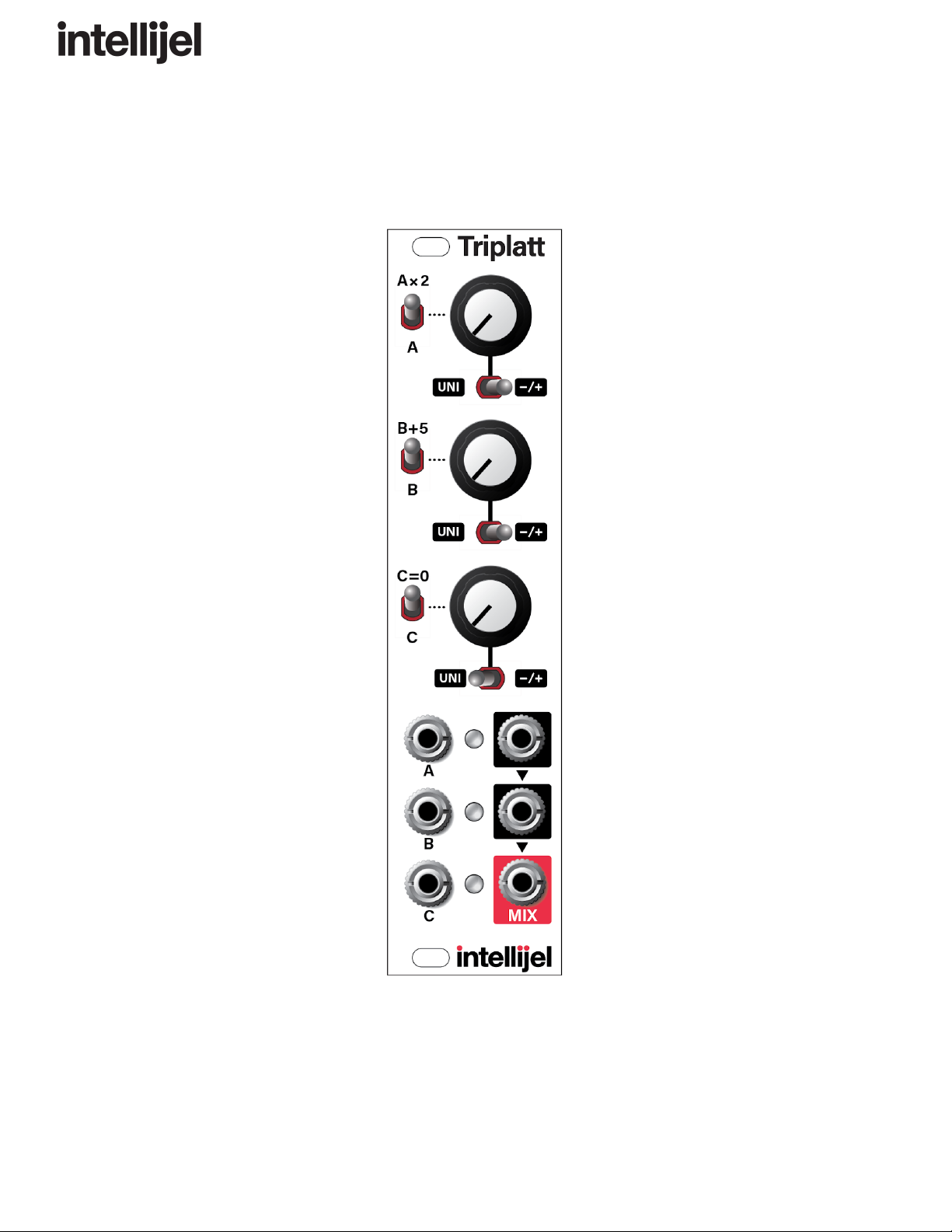
Triplatt
Triple Attenuator / Inverter / Attenuverter / Multiplier / Adder / Mixer / DC Voltage Source
Manual Revision: 2019.07.09


TriplattManual
Compliance
This device complies with Part 15 of the FCC Rules. Operation is subject to the
following two conditions: (1) this device may not cause harmful interference, and
(2) this device must accept any interference received, including interference that
may cause undesired operation.
Changes or modifications not expressly approved by Intellijel Designs, Inc. could
void the user’s authority to operate the equipment.
Any digital equipment has been tested and found to comply with the limits for a
Class A digital device, pursuant to part 15 of the FCC Rules. These limits are
designed to provide reasonable protection against harmful interference when the
equipment is operated in a commercial environment. This equipment generates,
uses, and can radiate radio frequency energy and, if not installed and used in
accordance with the instruction manual, may cause harmful interference to radio
communications.
This device meets the requirements of the following standards and directives:
EMC: 2014/30/EU
EN55032:2015 ; EN55103-2:2009 (EN55024) ; EN61000-3-2 ; EN61000-3-3
Low Voltage: 2014/35/EU
EN 60065:2002+A1:2006+A11:2008+A2:2010+A12:2011
RoHS2: 2011/65/EU
WEEE: 2012/19/EU
Page 2
TriplattManual
Installation
Intellijel Eurorack modules are designed to be used with a Eurorack-compatible case and power
supply. We recommend you use Intellijel cases and power supplies.
Before installing a new module in your case, you must ensure your power supply has a free
power header and sufficient available capacity to power the module:
● Sum up the specified +12V current draw for all modules, including the new one. Do the
same for the -12 V and +5V current draw. The current draw will be specified in the
manufacturer's technical specifications for each module.
● Compare each of the sums to specifications for your case’s power supply.
● Only proceed with installation if none of the values exceeds the power supply’s
specifications. Otherwise you must remove modules to free up capacity or upgrade your
power supply.
You will also need to ensure your case has enough free space (hp) to fit the new module. To
prevent screws or other debris from falling into the case and shorting any electrical contacts, not
leave gaps between adjacent modules, and cover all unused areas with blank panels. Similarly,
do not use open frames or any other enclosure that exposes the backside of any module or the
power distribution board.
You can use a tool like ModularGrid to assist in your planning. Failure to adequately power your
modules may result in damage to your modules or power supply. If you are unsure, please
contact us before proceeding.
Installing Your Module
When installing or removing a module from your case always
turn off the power to the case and disconnect the power cable.
Failure to do so may result in serious injury or equipment
damage.
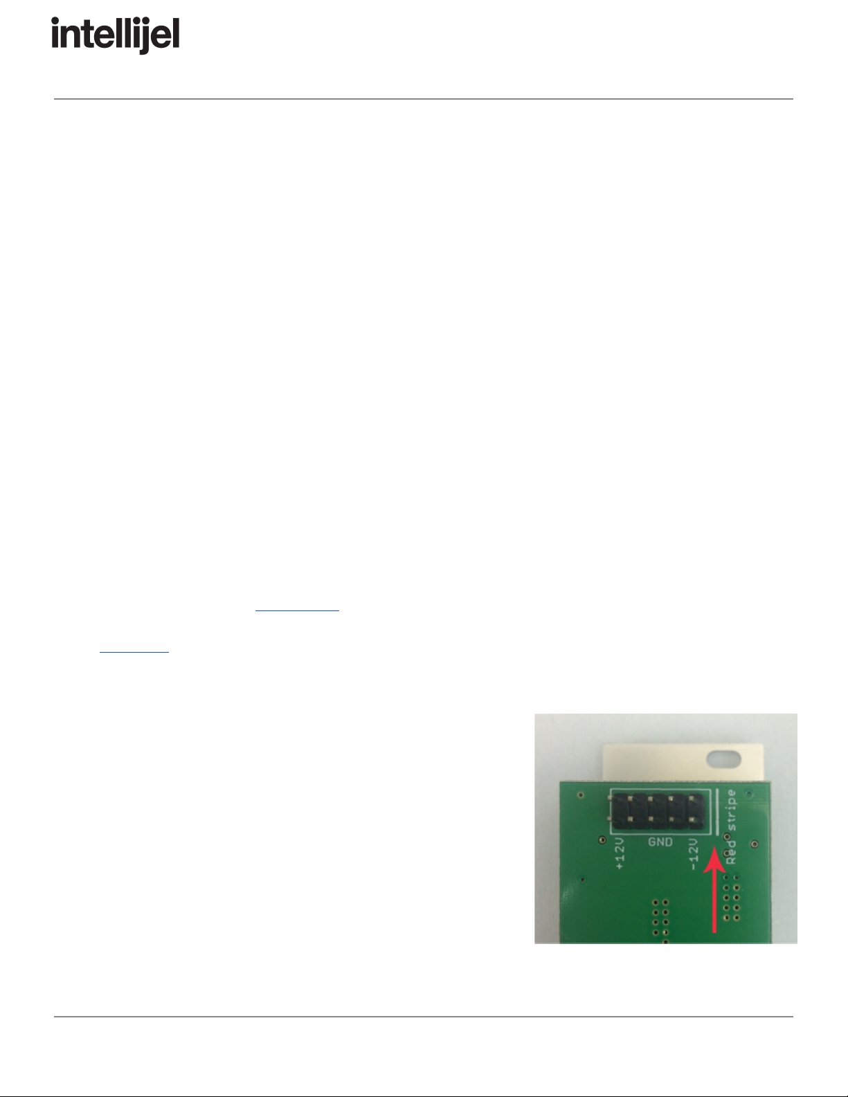
Ensure the 10-pin connector on the power cable is connected
correctly to the module before proceeding. The red stripe on
the cable must line up with the -12V pins on the module’s
power connector. Different modules use different ways to
indicate the -12V pins. Some may be labelled with “-12V;” a
white stripe next to the -12V pins; the words “red stripe;” or
some combination of these. Additionally, some modules may
have shrouded headers, thus preventing backward connections.
Page 3
TriplattManual
Most modules will come with the cable already connected but it is good to double check the
orientation. Be aware that some modules may have headers that serve other purposes so
ensure the power cable is connected to the right one.
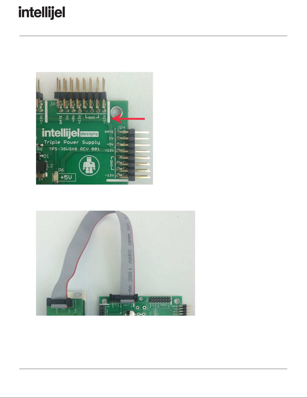
The other end of the cable, with a 16-pin
connector, connects to the power bus board of
your Eurorack case. Ensure the red stripe on
the cable lines up with the -12V pins on the
bus board. On Intellijel power supplies the
pins are labelled with “-12V” and a thick white
stripe.
If you are using another manufacturer’s power
supply, check their documentation for
instructions.
Once connected, the cabling between the module and power supply should resemble the
picture below:
Before reconnecting power
and turning on your modular
system, double check that
the ribbon cable is fully
seated on both ends and
that all the pins are correctly
aligned. If the pins are
misaligned in any direction
or the ribbon is backwards
you can cause damage to
your module, power supply,
or other modules.
After you have confirmed all
the connections, you can
reconnect the power cable and turn on your modular system. You should immediately check that
all your modules have powered on and are functioning correctly. If you notice any anomalies,
turn your system off right away and check your cabling again for mistakes.
Page 4

TriplattManual
Overview
Triplatt is a three-channel active/buffered attenuverter and summing mixer. Each channel has a
knob, which can function as a unipolar attenuator or a bipolar attenuverter, depending on the
setting of its corresponding two-position polarity switch.
Each input is normalled to a built-in +5V DC voltage source. With nothing plugged into the jacks,
each knob controls a voltage range of 0 to +5 V or -5 to +5 V depending on the position of the
channel polarity switch.
Each output is normalled to mix into the output of the channel below, making it possible to do
sub mixes in groups of two or three.
In addition, each channel has a “special function” switch to alter its input voltage in a specific
way. ChannelA has a 2x voltage multiplier switch, allowing you to double the voltage sent into
ChannelA. ChannelB has a +5V switch, allowing you to add 5V to whatever voltage is sent into
ChannelB. Channel C has a mute switch, allowing you to completely turn off the signal being
sent into ChannelC.
Page 5
TriplattManual
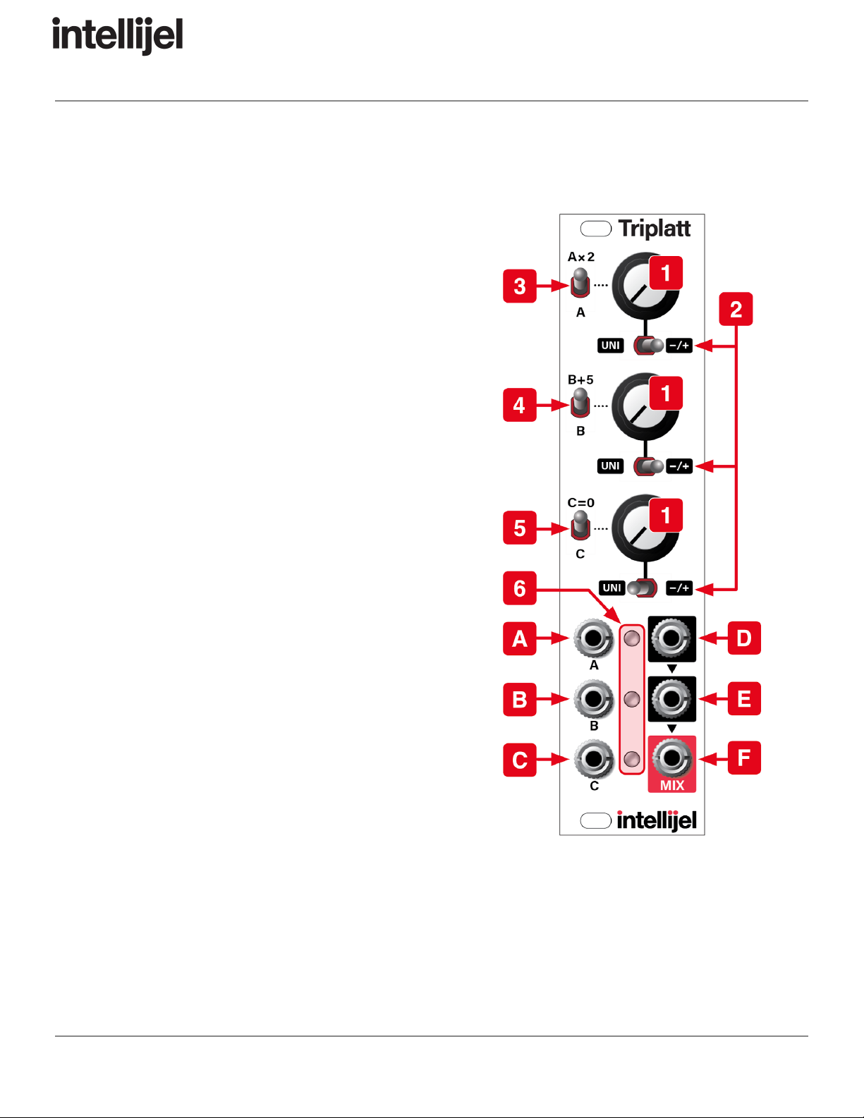
FrontPanel
Controls
1. Channel attenuator (x3)
These knobs attenuate the voltage present at the
input [A, B, or C] of each channel. The
behaviour of the knob depends on the position of
the Channel Polarity Switch [2] . The
attenuation amount is linear.
2. Channel polarity switch (x3)
This switch sets the polarity of the signal sent to
the output [D, E, or F] of each channel.
UNI: With the switch in the left UNI position, the
channel functions as a standard attenuator. The
full value of the channel’s input voltage is passed
through to the output when the attenuator knob
is fully clockwise . None of the input voltage
passes to the output when the attenuator knob is
fully counterclockwise ; and half the voltage
passes through to the output when the knob is at
the 12:00 (straight up) position.
-/+: With the switch in the right -/+ position, the
knob acts as a bipolar attenuverter. The full
value of the channel’s input voltage is passed
through to the output when the attenuator knob
is fully clockwise . The inverse of the input
voltage is sent to the output when the knob is
fully counterclockwise ; and none of the input
voltage passes through to the output when the
knob is at the 12:00 (straight up) position.
3. Ax2 switch
In the up (on) position, this switch doubles the voltage appearing at ChannelA’s input
[A] .
For example: leave the input of ChannelA unconnected; set the channel’s polarity switch
to -/+ , turn the channel attenuator fully clockwise; and set the Ax2 switch to the down
(off) position. Triplatt will send 5V to ChannelA’s input [A] . Flip the Ax2 switch to the up
Page 6

TriplattManual
(on) position, and Triplatt sends 10V (5V x 2) to ChannelA’s input. Rotate the knob fully
counterclockwise, and Triplatt sends -10V (-5V x 2) to ChannelA’s input.
The Ax2 switch is a convenient way to double the input voltage, or to set a full +10V or
-10V DC offset to the signal patched into ChannelB.
4. B+5 switch
In the up (on) position, this switch adds 5V to the input of ChannelB [B] .
This is particularly useful for converting a -5V/+5V bipolar signal (such as an LFO) into
a 0V-10V unipolar signal (which you can then attenuate with ChannelB’s attenuator
knob).
5. C = 0 switch
In the up (on) position, this switch mutes ChannelC’s input [C] , allowing you to
completely turn off the channel’s input, removing it from the ChannelC/MIX output [F] .
6. Output level/polarity LEDs (x3)
Each LED provides visual feedback of the voltage being sent out the corresponding OUT
jack. Green = positive voltage. Red = negative voltage. Brightness = absolute value of
output voltage (the LED is unlit when 0V is being sent to the output jack).
Page 7

TriplattManual
Inputs & Outputs
A. IN A
Input for Channel A. The voltage sent to this input is doubled (multiplied by 2) if the Ax2
switch [3] is on (up).
With no cable plugged in, Triplatt sends a 5V DC voltage into Channel A, which you can
double to 10V (5V x 2) with the Ax2 switch on. This input input voltage can then be
inverted with the polarity switch and scaled with ChannelA’s attenuator knob.
B. IN B
Input for Channel B. 5V is added to this input if the B+5 switch [4] is on (up).
With no cable plugged in, Triplatt sends a 5V DC voltage into ChannelB, which
becomes 10V (5V + 5V) with the B+5 switch on. The input voltage can then be inverted
with the polarity switch and scaled with ChannelB’s attenuator knob.
C. IN C
Input for Channel C. The input is switched off if the C=0 switch [5] is on (up).
With no cable plugged in, Triplatt sends a 5V DC voltage into ChannelC, which
becomes 0V with the C=0 switch on. You can invert the voltage appearing at INC using
a combination of ChannelC’s polarity switch and attenuator knob.
D. OUT A
Output for Channel A. If nothing it plugged into OUTA , then its voltage is bussed to the
next channel and summed with ChannelB’s output voltage. Plugging a cable into OUTA
prevents it from being summed with ChannelB’s output, or from appearing at the MIX
out [F] .
E. OUT B
Output for Channel B. If nothing is plugged into OUTA , then OUTB contains the sum of
ChannelA and ChannelB’s output voltages.
If nothing it plugged into OUTB , then its voltage is bussed to the next channel and
summed with ChannelC’s output voltage. Plugging a cable into OUTB prevents it from
being summed with ChannelC’s MIX out [F] .
F. OUT C / MIX
Output for ChannelC. With no cables connected to OUTA or OUTB this output is a
sum of the outputs of channels A, B, and C. Connecting a cable to OUTA removes its
output from the mix. Connecting a cable to OUTB removes both A and B’s outputs from
the mix.
Page 8

TriplattManual
UsageExamples
These simple parameters provide a wealth of useful functions to the modular synthesist. Here
are some basic examples of how you might employ Triplatt in your patches:
●Attenuation : Assume you want to subtly modulate filter resonance, but your filter of
choice doesn’t have a built-in attenuator on its resonance CV input. If you were to plug
the output of your LFO directly into the resonance CV input on your filter, you’d be
modulating it at full amplitude — meaning your LFO would cycle the resonance from
“none” to “ear shattering squelch” and back again. But what if you just want resonance to
undulate a little bit? Triplatt to the rescue!
Plug the output of your LFO into Triplatt’s INA , then plug OUTA into your filter’s
resonance CV jack. You’ll now be able to “dial down” the peak-to-peak amplitude of the
LFO using Triplatt’s attenuator knob.
●Inversion : Assume you want to control a module with an envelope. Normally, voltage
increases during the attack section of an ADSR, then decreases during the decay and
release segments. But what if you want the inverse? What if you want some sonic
attribute to get more pronounced as the signal decays, not less? For this you need to
invert the envelope. Once again, Triplatt to the rescue!
Plug the output of your envelope into Triplatt’s INA , set ChannelA’s polarity switch to
-/+ , then turn its attenuator knob counterclockwise past 12:00 — an inverted envelope
now appears at Triplatt’s OUTA .
●Voltage Offsets : Assume you have a Sample & Hold module sending random notes to
an oscillator, only you want to constrain that unruly 10 octave range of notes to just one
or two octaves in the bass range. One way to do this is to use two channels of a Triplatt.
Plug your S&H output into Triplatt’s INB ; connect OUTB to your oscillator’s pitch input;
then use the Channel B attenuator to limit the range of notes to an octave or two. Next,
use Triplatt’s Channel A (into which nothing is connected) to negatively offset the note
range down into the bass frequencies. Do this by setting Channel A’s polarity switch to
-/+ , then turn the corresponding attenuator knob counterclockwise past 12:00. Because
nothing is plugged into Triplatt’s OUTA , OUTB contains a sum of Channels A and B,
giving you both the reduced note range and the lower frequencies you desire.
●CV Mixing : What if you want to modulate some parameter with more than one control
voltage at a time? Perhaps you want to send a square wave to modulate a filter’s cutoff
frequency giving it a steady “pulsing” sound while simultaneously sweeping it with a
slow, triangular LFO. Triplatt is on the case. And, once again, you’ll be using two
channels.
Page 9

TriplattManual
Plug the square wave output of the “pulsing” LFO into Triplatt’s INA and connect OUTB
to your filter’s frequency CV input. Use ChannelA’s attenuverter to set the amount of
pulse you want to hear. Next, plug the triangle wave output of the “slow sweeping” LFO
into Triplatt’s INB . OUTB now contains of sum of Triplatt’s AandB channels. Use
Channel B’s attenuverter to set how much the pulse sweeps up and down the frequency
band. You now have two different CV sources controlling one destination by varying
amounts.
●Audio Mixing : Audio is a voltage too. So you’re probably asking yourself, “can I use
Triplatt to mix multiple channels of audio together as well?” Yes, you can!
Set all of Triplatt’s polarity switches to UNI and turn all its knobs fully counterclockwise .
Plug the output of one oscillator into INA , another into INB , and a third into INC .
Connect OUT C/MIX to your audio amplifier, and leave OUTA and OUT B unconnected.
Rotate ChannelA’s attenuator clockwise and you’ll hear the oscillator connected to INA .
Increase the ChannelB and ChannelC attenuators to add INB and INC to the mix.
●Instant Voltage Doubling : ChannelA has a dedicated multiplier switch, which doubles
the voltage being sent to its input. This is ideal for temporarily pumping up a CV’s impact
on a particular parameter, then instantly dropping it back down to its original level.
●Bipolar-to-Unipolar Conversion : ChannelB has a dedicated +5V switch, which adds
5V to the signal arriving at its input. This is particularly useful for converting a bipolar
signal (such as an LFO) into a unipolar signal. Connect the output of a bipolar LFO to
INB . Set ChannelB’s polarity switch to UNI , and its attenuator knob fully clockwise . With
the B+5 switch in the down (off) position, the -5V to +5V bipolar LFO is sent through to
OUTB without attenuation or conversion. Flip the B+5 switch to the on (up) position, and
a 0V to +10V unipolar LFO appears at OUTB . Turn the attenuator knob
counterclockwise to reduce the peak-to-peak amplitude of the unipolar LFO.
REMINDER: If nothing is plugged into to OUTA , then its value sums with ChannelB,
offsetting it accordingly. If you don’t want ChannelA’s value added to OUTB , connect a
dummy cable into OUTA , or set ChannelA’s attenuator to output 0V.
●Muting : ChannelC has a dedicated mute switch on its input. This is great for
instantaneously adding and removing a control voltage or DC offset to the value
appearing at OUTC/MIX .
Page 10

TriplattManual
BlockDiagram
Below is a block diagram of the signal flow through Triplatt:
TechnicalSpecifications
Width
6 hp
Maximum Depth
21 mm
Current Draw
49 mA @ +12V
25 mA @ -12V
Page 11
Table of contents
Other Intellijel Music Mixer manuals


