Intellijel TPS Series User manual
TPSManual
TPS Power Supplies
Triple Power Supply Product Range
Manual Revision: 2019.09.16

TPS Manual
Table of Contents
Table of Contents 1
Compliance 2
Overview 3
Common Features 4
TPS80W Triple Power Supply 4
TPS30 MAX Triple Power Supply 5
TPS30 Mini Triple Power Supply 5
Installation 6
Connecting to Power 6
Connecting Eurorack Modules 7
Connecting 5V Devices 8
Connecting CV & GATE 8
Using Multiple TPS Boards 8
Page 1

TPS Manual
Compliance
This device complies with Part 15 of the FCC Rules. Operation is subject to the
following two conditions: (1) this device may not cause harmful interference, and
(2) this device must accept any interference received, including interference that
may cause undesired operation.
Changes or modifications not expressly approved by Intellijel Designs, Inc. could
void the user’s authority to operate the equipment.
Any digital equipment has been tested and found to comply with the limits for a
Class A digital device, pursuant to part 15 of the FCC Rules. These limits are
designed to provide reasonable protection against harmful interference when the
equipment is operated in a commercial environment. This equipment generates,
uses, and can radiate radio frequency energy and, if not installed and used in
accordance with the instruction manual, may cause harmful interference to radio
communications.
This device meets the requirements of the following standards and directives:
EMC: 2014/30/EU
EN55032:2015 ; EN55103-2:2009 (EN55024) ; EN61000-3-2 ; EN61000-3-3
Low Voltage: 2014/35/EU
EN 60065:2002+A1:2006+A11:2008+A2:2010+A12:2011
RoHS2: 2011/65/EU
WEEE: 2012/19/EU
Page 2
TPS Manual
Overview
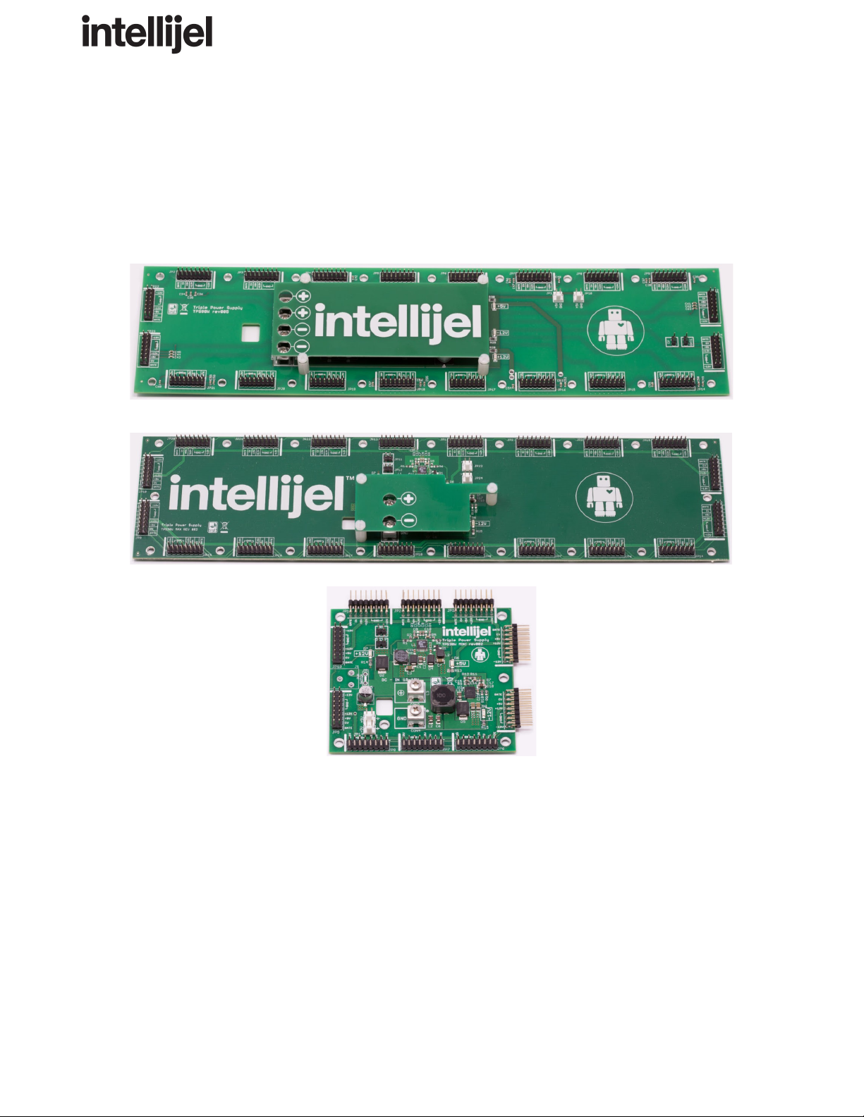
The TPS series of busboards and power supplies provides high power, efficient and low noise
studio-grade power to your Eurorack Modular case. It was designed to perform optimally with even
the most demanding, noisy and power hungry modules available today.
Each TPS busboard requires the purchase of an external power brick, plus either a 1U or 3U power
entry module (or DIY solution).
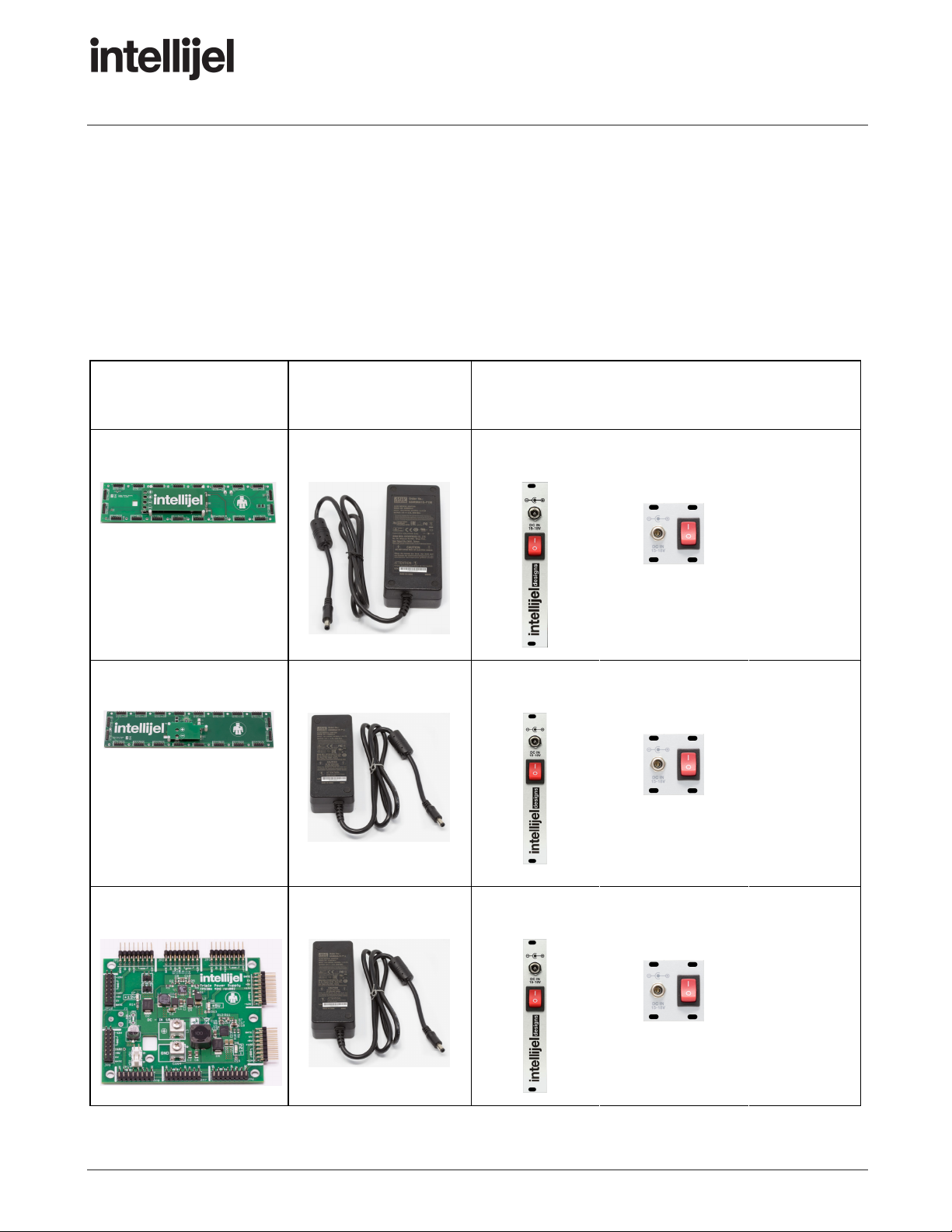
PRODUCT
+
POWER BRICK
+
A POWER ENTRY POINT
TPS80W
Meanwell 90W
Power Entry
(2.5mm)
Power Entry 1U
(2.5mm)
Intellijel
case with
integrated
entry point
or
DIY
solution
TPS30 MAX
Meanwell 60W
Power Entry
(2.1mm)
Power Entry 1U
(2.1mm)
Intellijel
case with
integrated
entry point
or
DIY
solution
TPS 30 MINI
Meanwell 60W
Power Entry
(2.1mm)
Power Entry 1U
(2.1mm)
Intellijel
case with
integrated
entry point
or
DIY
solution
Page 3

TPS Manual
Common Features
All TPS models share the following features:
● Low impedance star distribution due to 4 layer PCB
● Triple 120° phased controller for low induced noise
● Output short circuit protection and foldback current limiting
● Output overvoltage protection from transient overshooting
● Soft start for controlled start up operation
● +/-1% output voltage accuracy
● Two 2-pin molex headers for access to +5V bus
● Mounting holes can be used with 0.157″ / 4mm PEM snaps for quick install
TPS80W Triple Power Supply
In addition to the common features mentioned earlier, each TPW80W has the following additional
attributes:
● 80 Watt integrated switching power supply
● +12V output at 3000mA, -12V output at 3000mA, +5V output at 1500mA
● Includes 90W Meanwell power brick
● Connect up to 20 Eurorack modules
● 34cm wide x 8cm tall and max height of 20mm.
● Recommended for cases up to 7U x 104hp
Page 4

TPS Manual
TPS30 MAX Triple Power Supply
In addition to the common features mentioned earlier, each TPW30MAX has the following additional
attributes:
● 30 Watt integrated switching power supply
● +12V output at 1500mA, -12V output at 1500mA, +5V output at 1000mA
● Includes 60W Meanwell power brick
● Connect up to 20 Eurorack modules
● 34cm wide x 8cm tall and max height of 20mm
● Recommended for cases ranging from up to 7U x 84hp
TPS30 Mini Triple Power Supply
In addition to the common features mentioned earlier, each TPS30 Mini has the following additional
attributes:
● 30 Watt integrated switching power supply
● +12V output at 1200mA, -12V output at 1200mA, +5V output at 500mA
● Includes 60W Meanwell power brick
● Connect up to 10 Eurorack modules
● 9cm wide x 8cm tall and max height of 20mm
● Fits comfortably in a tiny skiff but can power larger cases
Page 5
TPS Manual
Installation
Each model of TPS busboard features integrating mounting holes, so you can secure the busboard to
the inside of your case. If you’re mounting inside a wood case, you can use screws with standoffs to
raise the board off the mounting surface, or you can use 0.157″/4mm PEM snaps for quick
installation.
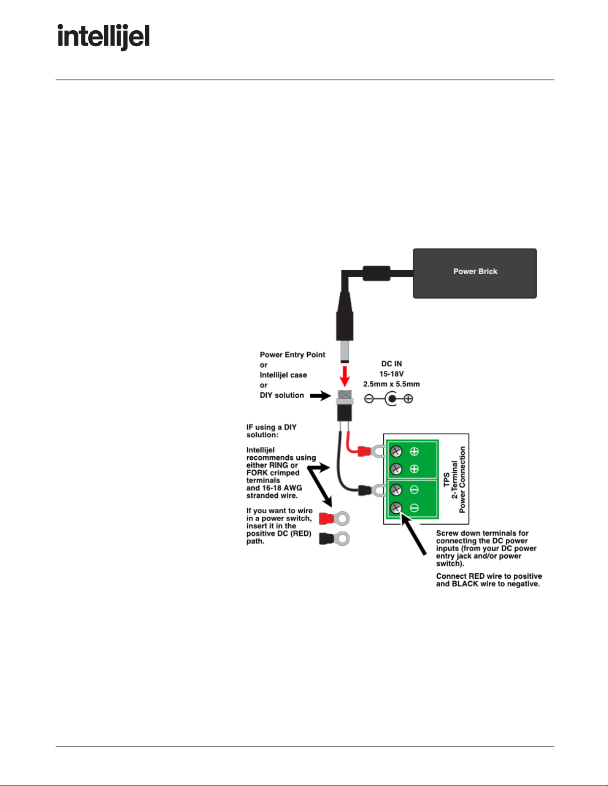
Connecting to Power
You will need to connect the
busboard to power. This can mean:
1) using an Intellijel Power Entry
module (3U or 1U), or
2) using an Intellijel case with a
built-in Power Entry, or
3) building your own DIY solution.
The illustration to the right shows
how to supply power to your TPS
busboard.
Specifically, connect the RED wire
(center pin) to the POSITIVE screw
terminal on the TPS board. Connect
the BLACK wire (sleeve) to the
NEGATIVE (or GND) screw terminal
on the TPS board.
NOTE: Some TPS busboards (like
the TPS80) have two pairs of screw
terminals (as shown in the illustration
to the right), and some (like the
TPS30) have only a single pair of screw terminals.
IMPORTANT : Never exceed the maximum amperage rating of your TPS busboard. Look up the
power specs for each module you connect, and sum their amperages to make sure they total less
than the rating of the circuit board. Ideally, you should also use a Power Brick that exceeds this
amperage, to give you plenty of overhead.
Page 6
TPS Manual
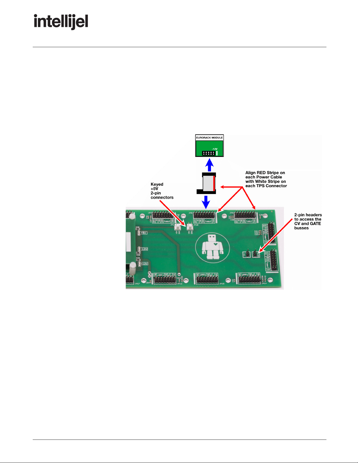
Connecting Eurorack Modules
Running around the circumference of the three TPS busboards are the power headers.
These headers power your eurorack modules using the ribbon cables included with each of your
modules.
Align each ribbon cable’s RED stripe with the WHITE stripe printed on the TPS busboard. The white
stripe indicates which pins are -12V.
Plug the other end of each
ribbon cable into the Eurorack
modules you wish to power —
being careful to align the red
stripe with the -12V pins on
the module. These pins are
indicated differently by
different manufacturers, but
often will say “-12V,” or “Red
Stripe,” or have a visible white
stripe next to the -12V side of
the connector. See your
Eurorack modules’ manual for
details concerning their -12V
power nomenclature.
NOTE : The TPS80W and
TPS30 MAX both contain
20power headers. The
TPS30 MINI contains
10power headers.
Page 7

TPS Manual
Connecting 5V Devices
Connect these 5V connectors to any modules that require a 5V power source. You can also use this
to power an Intellijel USBPower1U module, which (for example) is useful for connecting a small USB
gooseneck LED light.
Connecting CV & GATE
All TPS busboards have CV and GATE connections per the Eurorack standard.
Using Multiple TPS Boards
If you need more power headers than are on your TPS busboard, you have a few options:
● OPTION ONE: Multiple TPS Systems
You can simply install additional boards and power each from its own dedicated power brick.
● OPTION TWO: Flying Bus Cable
You can use a flying bus cable to gain additional headers. However, Intellijel does not
recommend this option, since you may experience more noise than if you connect all your
modules directly to TPS busboards.
● OPTION THREE: Daisy-Chain Busboards on a Single Power Brick
You can install multiple boards and daisy-chain them to a single power brick. This option is
preferable to Option Two, and requires the following steps:
1. Do the math.
Decide which modules you want connected to each busboard, then add up their total
amperage, and confirm it doesn’t exceed the amperage rating of each TPS busboard.
Use a Power Brick that provides at least as much power as the sum total of all
daisy-chained busboards. For example, the TPS30 MAX and TPS30Mini are both
30W busboards, so you should use at least a 60W power brick when powering them
both.
HINT: A busboard’s power requirements are reflected in its name. The TPS30 boards
require 30W of power; the TPS80 boards require 80W of power.
Page 8
TPS Manual
2. As described previously, connect the RED wire from the Power Entry point to the first
busboard’s POSITIVE terminal, and connect the BLACK wire from the Power Entry
point to the first busboard’s NEGATIVE terminal.
Some boards have two pairs of DC connectors, so simply connect the RED wire to one
of the two POSITIVE terminals, and the BLACK wire to the corresponding NEGATIVE
terminal.
3. Using 16-18 AWG stranded wire, connect the POSITIVE terminal on TPS1’s busboard
to the POSITIVE terminal on TPS2’s busboard.
4. Similarly, connect the NEGATIVE terminal on TPS1’s busboard to the NEGATIVE
terminal on TPS2’s busboard.
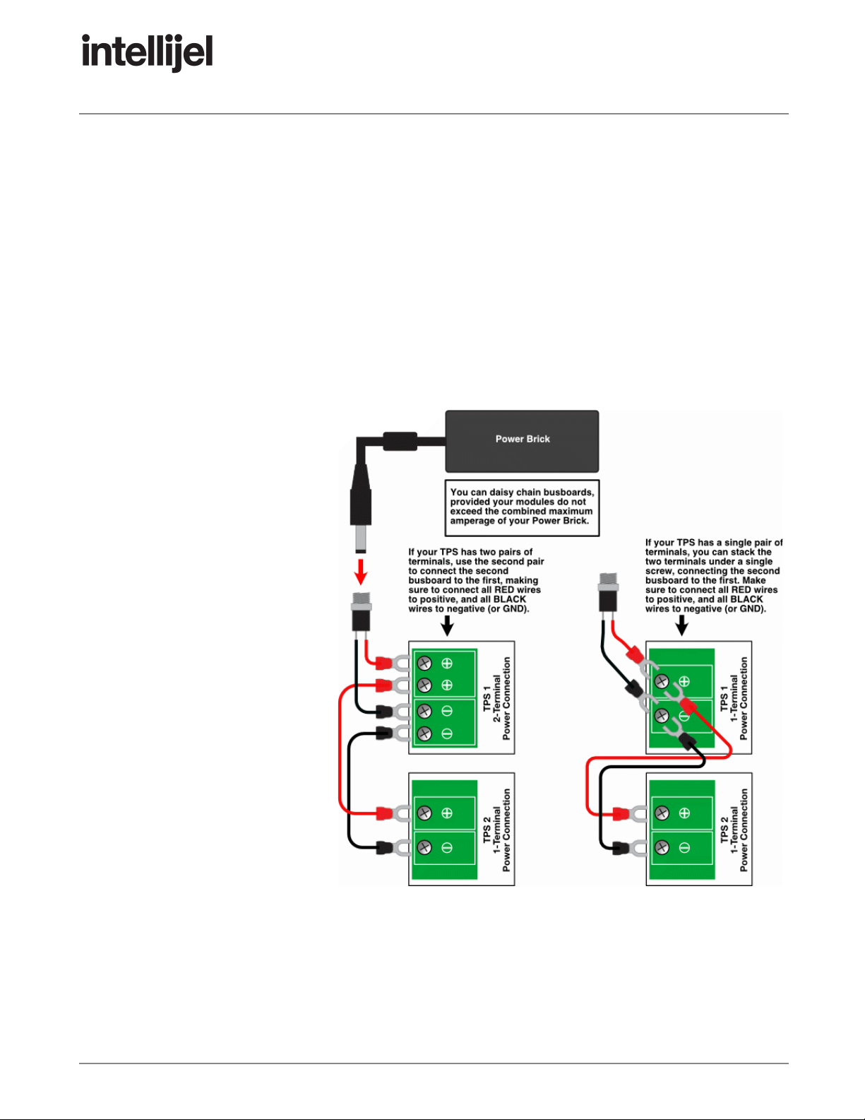
If the first busboard
has two pairs of DC
connectors (like the
TPS80), simply
make the
daisy-chain using
the second pair of
terminals, as shown
here.
If the first busboard
has a single pair of
DC connectors (like
the TPS30), you can
stack the two
terminal
connections under a
single screw to
complete the
daisy-chain (as
shown here).
Page 9
This manual suits for next models
3
Table of contents
Popular Power Supply manuals by other brands


Vertiv
Vertiv NetSure7100 Series user manual

Rockwell Automation
Rockwell Automation Allen-Bradley 1606-XLE192BM manual

HP
HP 6033A series Service manual

Intelligent Motion Systems
Intelligent Motion Systems ISP300 datasheet

Pulsar
Pulsar EN54-2A17 manual

Analytic Systems
Analytic Systems IBI Series Installation & operation manual

Whelen Engineering Company
Whelen Engineering Company UPS690 installation guide

Granit
Granit GN3000 user manual

Pulsar
Pulsar PSBOC15512110 manual

RKC INSTRUMENT
RKC INSTRUMENT SR Mini HG SYSTEM H-PCP-J instruction manual

MGC
MGC QPS-5000N installation instructions

Velleman
Velleman HQPOWER PS3003 user manual