MGC QPS-5000N User manual

LT-1107 Rev 4.1
Aug 2015
Page
1of 3
QPS-5000N
Audio Power Supply
Installation Instructions
The QPS-5000N Audio Power Supply may be used with the QBC-5000N Battery Charger (Network) as well as the QBC-
5000B Battery Charger (Non-network).
QPS-5000N Audio Power Supply for Network System
The QPS-5000N Audio Power Supply mounts into the QBB-5001(R) or the MMX-QBB-5001(R) expansion audio
cabinet. The power supply chassis mounts into the bottom left section of the audio cabinet as shown in Figure 1 below.
On the top portion of the power supply chassis is a battery disconnect relay.
Figure 1:
QBB-5001(R)/MMX-QBB-5001(R) Expansion Audio Cabinet Module Placement
12 VDC BATTERY 12 VDC BATTERY
INLINE FUSE 50A
- BATTERY +
XFORMER
Black
Black
L N
120 or
240 VAC
Input
IN OUT
Red
Red
QBC-5000N
QMB-5000B
Motherboard
BATTERY
CHARGER
CONNECTORS FOR MULTIPLE
QMB-5000B MOTHERBOARDS
SLOT #1
CONNECTOR IS
NOT USED
SLOTS #2 - #8
CONNECTORS FOR
QAA- STYLE AMPLIFIERS
CONNECTOR FOR QBC-5000N
BATTERY CHARGER
QPS-5000N
POWER
SUPPLY
SECURE QPS-5000N POWER SUPPLY TO BACKBOX WITH LUGS AND NUTS PROVIDED
TS1
JW1
Orange-Yellow-Orange
(MUST BE IN CORRECT ORDER)
Battery
Disconnect
Relay
Connecting wires are provided with the
QPS-5000N Power Supply Chassis.
LT-1107 Rev 4.1
Aug 2015Page 2 of 3
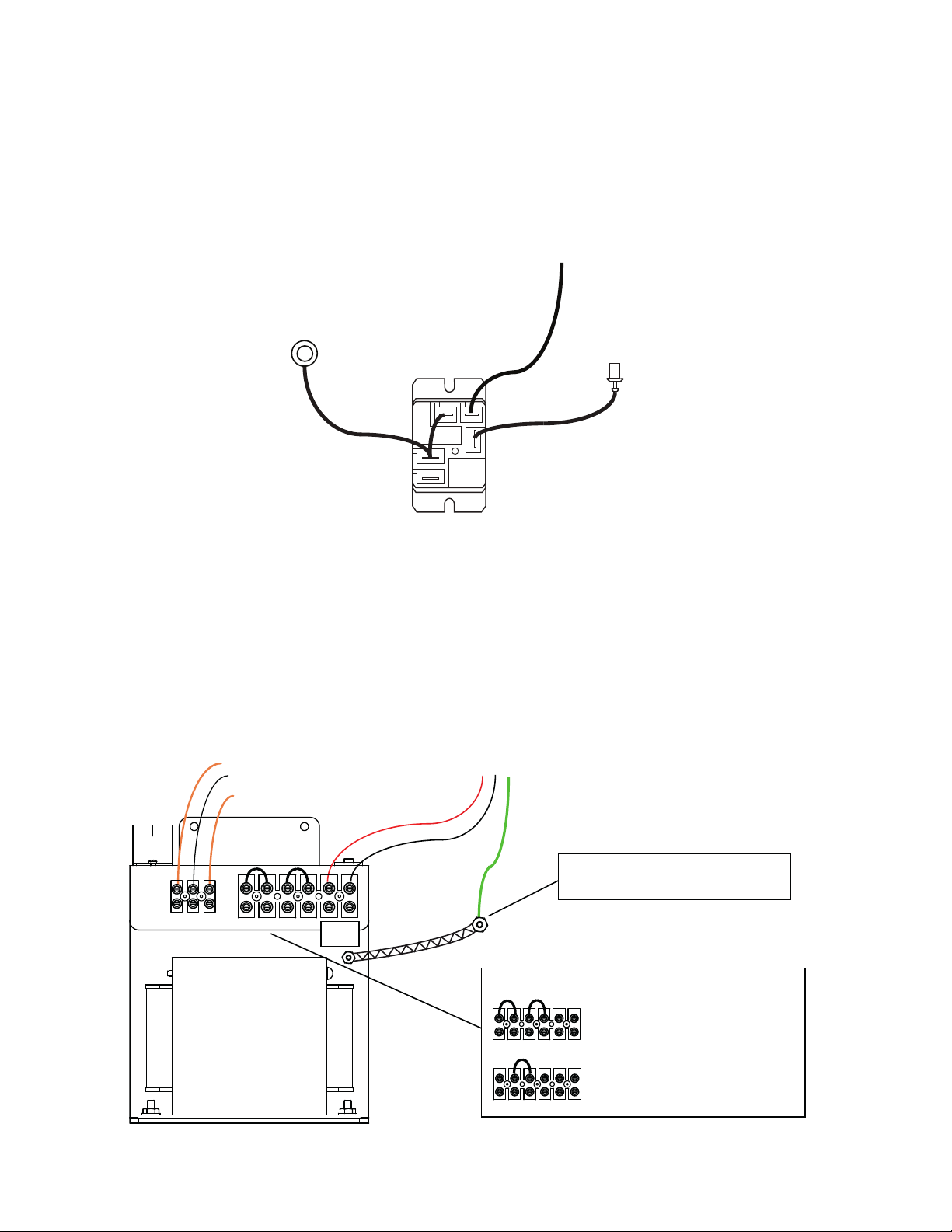
Connect QBC and Battery Wires to the QPS-5000N Power Supply Battery Disconnect Relay
Two red wires are provided with the power supply to hook up the Battery Disconnect Relay. The other wire to be connected
to the Battery Disconnect Relay comes from the QBC-5000N Battery Charger (the red wire soldered to the board or the
red/blk cable WX-518) with a lug connector on the end (refer to Figure 1). Wire as noted in Figure 2 below.
Figure 2: Battery Disconnect Relay Wiring (Relay located on the QPS-5000N Power
Supply Chassis)
Select QPS-5000N Power Supply Voltage
Two jumpers are factory set as shown in Figure 3 below for 120 VAC connection. For 240 VAC application, remove both
jumpers and replace one jumper between the two middle terminals, see Figure 3. The two terminals on the right are
L (live) and N (neutral), for AC supply. The three terminals on the left are connected to the orange-white-orange wires
from the QMB-5000B motherboard.
Figure 3: AC Voltage Wiring to QPS-5000N
Battery Disconnect Relay
(Top View)
Connect to the inline fuse
Connect to positive
side of Battery (see
Figure 1)
Red wire from the
QBC-5000N Battery Charger
connects to Battery Disconnect
Relay here
WX-517
WX-516
Orange- White-Orange
Wires connected to
QMB-5000B Motherboard
120 VAC or
240 VAC
Live (Black) Ground
Earth Ground stud in QBB-5001 Backbox
Neutral (White) Connect AC ground to Earth Ground
stud located in the QBB-5001 Backbox.
L N
L N
L N
QPS-5000N 120 VAC Select
120/240 VAC SELECTION
OR
240 VAC Select
Default Jumper Positions
Discard unused Jumper
Ground Braid

LT-1107 Rev4.1
Aug 2015
Page
3of 3
QPS-5000N Audio Power Supply for Non-network
The QPS-5000N can be used with the QBC-5000B Battery Charger as well as the QBC-5000N Battery Charger. When
using either Battery Charger for a non-network audio system, connect as shown in Figure 4 below. Remove the WX-518
connector from the QBC-5000N and discard. For battery connection discard the WX-517 wire (packaged with the QPS-
5000N) and use the battery connectors which come with the QMB-5000B motherboard to connect the batteries as shown
in Figure 4.
Figure 4: QPS-5000N and QBC-5000B or QBC-5000N Connection and Module
Placement within a Non-network Audio Cabinet QBB-5001(R)
Select QPS-5000N Power Supply Voltage
Jumpers are set for 120V AC as default. Rearrange jumper if 240V AC is required, see page 2 and Figure 3.
Note: Ensure that the circuit board MD-924 is Rev G or higher.
i
12 VDC BATTERY 12 VDC BATTERY
INLINE FUSE 50A
- BATTERY +
XFORMER
Black
L N
120 or
240 VAC
Input
IN OUT
Red
QBC-5000B/N
QMB-5000B
Motherboard
BATTERY
CHARGER
CONNECTORS FOR MULTIPLE
QMB-5000B MOTHERBOARDS
SLOT #1
CONNECTOR
FOR QIF-5000B
SLOTS #2 - #8
CONNECTORS FOR
QAA- STYLE AMPLIFIERS
CONNECTOR FOR QBC-5000B/N
BATTERY CHARGER
QPS-5000N
POWER
SUPPLY
SECURE QPS-5000N POWER SUPPLY TO BACKBOX WITH LUGS AND NUTS PROVIDED
TS1
JW1
Orange-Yellow-Orange
(MUST BE IN CORRECT ORDER)
Connecting wires are provided with the
QPS-5000N Power Supply Chassis.
Use ONLY WX-517 to connect to positive
side of the battery as shown here.
Disconnect Red/Blk Cable
WX-518. NOT USED. Ensure that the
circuit board
MD-924 is Rev
G or higher.
Table of contents
Other MGC Power Supply manuals


Popular Power Supply manuals by other brands


elsner elektronik
elsner elektronik KNX PS640 Technical Data and Installation Notes

Capetti Elettronica
Capetti Elettronica Winecap BOX-PPS user manual

Thermaltake
Thermaltake TOUGHPOWER GF1 ARGB 850W user manual

Altronix
Altronix SMP7 installation instructions

Velleman
Velleman PSSEMV25 user manual

SGC
SGC SG-2020 TEST DOCUMENT user manual