2 Function
2.1 Input voltage range
¡The range is from AC85V to AC264V. (please see SPECIFICA-
TIONS for details).
¡In cases that conform with safety standard, input voltage range is
AC100 - AC240V (50/60Hz).
¡If input value doesn’t fall within above range, the unit may not op-
erate in accordance with specications and/or start hunting or fail.
If you need to apply a square waveform input voltage, which is
commonly used in UPS and inverters, please contact us.
¡When the input voltage changes suddenly, the output voltage ac-
curacy might exceed the specication. please contact us.
2.2 Inrush current limiting
¡An inrush current limiting circuit is built-in.
¡If you need to use a switch on the input side, please select one
that can withstand an input inrush current.
¡Relay technique is used in the inrush current limiting circuit. When
you turn the power ON/OFF repeatedly within a short period of
time, please have enough intervals so that the inrush current limit-
ing circuit becomes operative.
¡Surge current in the lter unit does not include (0.2ms or less).
2.3 Overcurrent protection
¡An overcurrent protection circuit is built-in and activated at 105%
of the rated current. A unit automatically recovers when a fault
condition is removed.
Please do not use a unit in short circuit and/or under an overcur-
rent condition.
¡Intermittent Operation Mode
Intermittent operation for overcurrent protection is included in a
part of series. When the overcurrent protection circuit is activated
and the output voltage drops to a certain extent, the output be-
comes intermittent so that the average current will also decrease.
¡Output voltage shuts down when the output voltage continuously
drops due to overcurrent protection.
¡Output voltage recovers from overcurrent protection by shutting
down the input voltage and waiting more than 3 minutes then turn-
ing on AC input again.
2.4 Overvoltage protection
¡An overvoltage protection circuit is built-in. If the overvoltage pro-
tection circuit is activated, shut down the input voltage, wait more
than 3 minutes and turn on the AC input again to recover the out-
put voltage.
Remarks :
Please avoid applying a voltage exceeding the rated voltage to an
output terminal. Doing so may cause a power supply to malfunc-
tion or fail. If you cannot avoid doing so, for example, if you need
to operate a motor, etc., please install an external diode on the
output terminal to protect the unit.
2.5 Output voltage adjustment range
¡To increase an output voltage, turn a built-in potentiometer clock-
wise.
To decrease the output voltage, turn it counterclockwise.
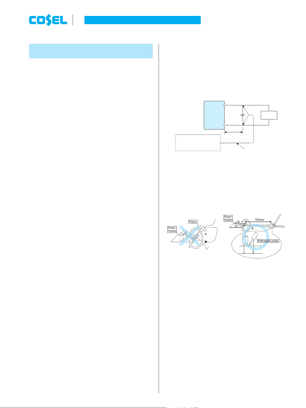
2.6 Output ripple and ripple noise
¡Output ripple noise may be inuenced by measurement environ-
ment, measuring method Fig.2.1 is recommended.
Load
150mm
C
1
Osiloscope/
Ripple noise meter
Bw:20MHz
Differential probe
+
C1 : Aluminum electrolytic capacitor 22μF
+V1
G1
Fig.2.1 Measuring method of Ripple and Ripple Noise
(Example of measurement with V1)
Remarks :
When GND cable of probe with ux of magnetic force from power
supply are crossed, ripple and ripple noise might not measure cor-
rectly.
Please note the measuring environment.
Bad example Good example
Fig.2.2 Example of measuring output ripple and ripple noise
2.7 Isolation
¡For a receiving inspection, such as Hi-Pot test, gradually increase
(decrease) the voltage for the start (shut down). Avoid using Hi-
Pot tester with the timer because it may generate voltage a few
times higher than the applied voltage, at ON/OFF of a timer.
¡When you test a unit for isolation between the input and output, or
between output and terminal FG, short-circuit between all outputs
and function terminal.
¡When you test a unit for isolation between output V1,V2, and out-
put V3,short-circuit between output V1 and output V2.
2.8 Start/stop sequence
¡The start / stop waveform changes due to external capacity, load
current, etc, so please evaluate if start / stop sequence is required.
¡Please contact us if start / stop sequence is required.
AC-DC Power Supplies Congurable Type
Instruction Manual
RB-9