Intellipure 950P User manual
Operation Manual
Intellipure 950P COMMERCIAL PORTABLE
AIR PURIFICATION SYSTEM


Table of Contents
Part Number: #10065IN
Copyright: © 2020 All rights reserved.
Address: Intellipure, Inc.
3420 Maple Ave.
Pulaski, NY 13142
Phone No: 315-298-2904
1-800-843-3860
Email: info@intellipure.com
Limited Warranty ......................................4
Safety Precautions ...................................5
Receiving and Unpacking........................5
Receiving
Storage
System Overview .....................................6
Unit Description
Component Description
Installation Procedures.............................7
Power Requirements
Location Determination
System Operation ....................................8
Maintenance ..................................... 10 -13
Prefilter Replacement
V-Bank Main Filter Replacement
Cleaning the Unit
Parts List
Voltage Adjustments ..............................13
Troubleshooting .....................................14
System Schematic .................................15

Intellipure © 2021 All rights reserved.
4
Limited Warranty
Intellipure offers a 5 Year Limited Warranty. 5 Years on motor and blower and 1 year on electronic components.
A return authorization must be obtained before any product is shipped to the manufacturer for warranty repair
and all transportation charges must be prepaid all work must be performed by a Intellipure authorized technician.
The sole responsibility of Intellipure under this Limited Warranty is, at its sole discretion, to either repair or replace a
duly registered product (or defective part thereof) with the same comparable model within a reasonable period of
time, subject to the following exclusions, limitations, statutory rights, and warranty claim procedures. This Limited
Warranty is exclusive, and Intellipure expressly disclaims all other or additional warranties, whether written or oral,
expressed or implied, including, but not limited to, warranties of merchantability, workmanship, or tness for a
particular purpose.
EXCLUSIONS
A. This Limited Warranty does not apply, or is void, as to any product or part damaged by (1) accident, misuse,
abuse, or lack of reasonable care or normal maintenance; (2) installation or operation under conditions other
than those recommended by Intellipure; (3) subjection of the product to any but the specified voltage;
(4) servicing or disassembly by unauthorized personnel; (5) defacing the serial number; or (6) modifying the
original factory assembled unit in any way.
B. THIS LIMITED WARRANTY DOES NOT APPLY TO SHIPPING CHARGES FOR PRODUCT SHIPPED TO OR FROM THE
FACTORY OR DESIGNATED SERVICE CENTER IN CONNECTION WITH WARRANTY CLAIMS NOR DOES IT APPLY
TO ANY DAMAGES OCCURRING DURING SUCH SHIPMENT.
C. This Limited Warranty does not apply to labor for installation, removal, re-installation, and/or travel or ship-
ping expenses and related expenses.
This Limited Warranty does not apply to replaceable lters.
LIMITATIONS
Intellipure shall not be liable for property, incidental, and/or consequential damages of any kind and, unless otherwise
prescribed by applicable state law, Intellipure shall not be liable for personal injury resulting from malfunc-
tions, defects, misuse, improper operation or installation, or alteration of a Intellipure product or any part thereof.
The exclusive remedy for a breach of this Limited Warranty is the repair or replacement of the defective product. In
no case, shall liability under any other remedy prescribed by law exceed the purchase price of the product.
WARRANTY CLAIM PROCEDURE
This information is provided as a guide regarding warranty claim procedures for Intellipure Products, Inc air
purication systems.
1. Determine model number from the label on the unit.
2. For technical support, warranty information, warranty parts or replacement parts, call Intellipure Products
at 315-298-2904 or 1-800-843-3860 from 8:00 AM-5:00 PM EST a Intellipure representative will help you
troubleshoot and diagnose the problem. Warranty matters involving products sold through a manufactur-
er representative should be directed to the appropriate representative.
3. Important: Do NOT return anything without a Return Authorization.
4. All returned parts are quality tested. If the returned part is found not to be defective, you may be invoiced for
the new part.

Intellipure 950P
5
Receiving and Storage
RECEIVING
Your unit has been carefully packed to avoid damage in shipping and storage. Equipment is prepared for shipment in
accordance with the Uniform Freight Classication. It is thoroughly inspected at the factory and barring damage in
transit, should be received in good condition.
When a freight carrier signs the Intellipure bill of lading, the carrier accepts the responsibility for any subsequent
shortages or damage evident or concealed. Inspection by the carrier of damage evident or concealed must be
requested. Evident shortage or damage should be noted on the carrier’s delivery document before signature of
acceptance. Claims must be made against the carrier by the purchaser.
Filtration systems are shipped as fully assembled lter units.
STORAGE
Store it in a dry place protected against moisture, dust, physical damage, weather, corrosion and excessive heat/cold.
Must install the Prelter and V-Bank Main Filter before turning on the unit.
Safety Precautions
This symbol will be used throughout this manual to indicate safety
checkpoints. Failure to heed these warnings and notices may result
in damage to the unit and/or injury to personnel.
SAFETY PRECAUTIONS
Personnel, who will operate this system, or those who will perform maintenance thereon, must be given all manuals and
other instructions regarding safe operation of the ltration system.
The appliance is not to be used by persons (including children) with reduced physical, sensory, or mental capabilities, or
lack of experience and knowledge, unless they have been given supervision or instruction.
Children being supervised are not to play with the appliance.
This manual contains general recommendations, but specic requirements may apply to individual
installations. Such requirements are outlined in federal, state, and local codes. Compliance with
applicable codes and strict adherence to these installation instructions are the sole responsibility of the user.
Intellipure © 2021 All rights reserved.
6
System Overview
COMPONENT DESCRIPTION
The 950P Portable DFS Air Cleaning System integrates the system components into a single, portable unit: the Prelter,
V-Bank Main Filter and the High Energy Grid are accessible from the lter access door.
Electrical controls are located on the front of the unit. It consists of the Main Power ON-OFF switch with a Blue LED to
indicate High Voltage Power Supply power status, Blower Speed Status and Blower Speed Control Switch.
Replacement Filters Eciency Replacement Period*
Prelter MERV-8 (35% Eciency) 1-2 times per year
VOC Post Filter (When equipped)
Formaldehyde > 99%
Benzine > 99%
Toluene > 99%
Optional V-Bank: once a year
DFS V-Bank
Main Filter
99.99% Ecient
(down to .007 microns) once a year
UNIT DESCRIPTION
The Air Cleaning System is a high performance system that utilizes patented award-winning Disinfecting Fil-
tration System technology. DFS technology electrically converts a low pressure drop filter to high efficiency while
retaining the low pressure drop and longer life advantages of the base lter material. This technologyhas also been
shown to inhibit bacteria growth on the lter.
The Electrical Components are located in an enclosed electrical box inside the unit.
The 950P Portable DFS Air Cleaning System is available in the following models:
Height Width Depth Weight
950P 44in 1,118mm 18in 457mm 28in 711mm 155 lb 70 kg
With VOC Filter 57in 1,448mm 18in 457mm 28in 711mm 215 lb 98 kg
Please conrm your model number and follow the instructions for that
model. The electrical power requirements for each individual unit are on
the data plate label. These requirements supersede all other inferences
to power requirements.
Intellipure 950P
7
Installation Procedures
POWER REQUIREMENT
The power requirements are as follows:
*Electrical disconnects may also be required - check local electrical codes
Model
Power Requirement FLA Power Usage
Max Start-up
VHz Phase AMPS WAT TS
950P 120 60 1 3.3 390
950P 220 50 1 1.71 390
LOCATION DETERMINATION
The 950P is designed as a portable oor model, the location and operation of the unit shall follow state /local code for
installation of electrical devices.
Place the air purier anywhere in the room and on a at and level surface to allow continuous airow to the bottom intake
and out the top outlet grill.
For best performance, it is recommended to place the air purier at least two (2) feet from walls and other obstructions.
Do not place the air purier where drapes or other objects block airow.
Always lock both casters.
Do not run power cord under carpeting or near heaters, registers, radiators, stoves or replaces. To avoid a tripping hazard,
keep the power cord away from trac areas.
Never operate the air purier in areas where combustible gases or vapors are present or any other ammable materials.
Do not operate unit using an extension cord.

Intellipure © 2021 All rights reserved.
8
System Operation
ELECTRICAL CONNECTION
Inspect power cord for damage before plugging in. The outlet must be grounded. If the supply cord is damaged,
it must be replaced by a special cord or assembly available from the manufacturer or its service agent.
f-1 g-1 h-1
i-2f-2 g-2 h-2
edcba
a) Power button
b) Sleep mode
c) Slide speed control
d) High speed
e) Turbo mode
f-1) VOC Pre-lter indicator
f-2) Change VOC pre-lter indicator
g-1) Main lter indicator
g-2) Change main lter indicator
h-1) VOC post-lter indicator
h-2) Change VOC post-lter indicator
i-1) DFS indicator
i-2) DFS deactivation indicator
Disconnect power to the unit before servicing. Moving Parts inside. Wait
30 seconds after turning the unit o before opening the Filter Access Door.
The touch control technology is designed to operate under minimal pressure.
Lightly touch or slide over the buttons for an optimal user experience.
i-1
On-board Touch Pad Diagram

Intellipure 950P
9
System Operation
POWER ON / OFF
1. When unit is plugged in, control goes through self-diagnosis and then returns to the last setting before power was lost.
2. When unit is o (and plugged in), only the power button is dimly lit.
SPEED CONTROL
1. When unit is turned on, Power Button, Speed Bar, DFS and Filter Lights will be illuminated white.
2. Touch the fan speed bar to increase or decrease fan speed by increments of four.
3. For ne-tuning Speed:
a. Touch the small fan symbol (button b in On-board Touch Pad Diagram) to decrease fan speed by 2 increments.
b. Touch the large fan symbol (button d in On-board Touch Pad Diagram) to increase fan speed by 2 increments.
SLEEP MODE
1. Adjust to desired speed for Sleep Mode. Press & hold Sleep Mode Button for 5 seconds to activate Sleep Mode.
2. When Sleep Mode is activated, the whole user interface will dim to low. Only the Power Button and Sleep Mode Button
are lit. The unit will remain running at the speed set before Sleep Mode was activated.
3. To deactivate Sleep Mode, touch anywhere in the speed bar.
TURBO MODE
1. Touch Turbo Mode button to activate Turbo Mode.
2. When activated, all buttons on the On-board Touch Pad are illuminated white.
3. To deactivate Turbo Mode, touch anywhere in the speed bar.
FILTER INDICATOR 1/2/3
1. When unit is operating properly, the lter indicators are illuminated white.
2. When lter lifespan has been reached, lter indicator goes out and change lter indicator turns red.
3. Filter light can be reset by holding the respective lter light button for 5 seconds. When lter indicator quickly ashes
6 times, the timer is successfully reset.
DFS INDICATOR
1. When unit is on and DFS is operating properly, the indicator lit in white.
2. When DFS needs maintenance, DFS will automatically turn o. When DFS is turned o, indicator turns RED.
3. DFS can be activated / deactivated by touching DFS button. When DFS is deactivated, the DFS indicator turns o and
DFS deactivation indicator turns red.
Intellipure © 2021 All rights reserved.
10
Maintenance
PREFILTER REPLACEMENT
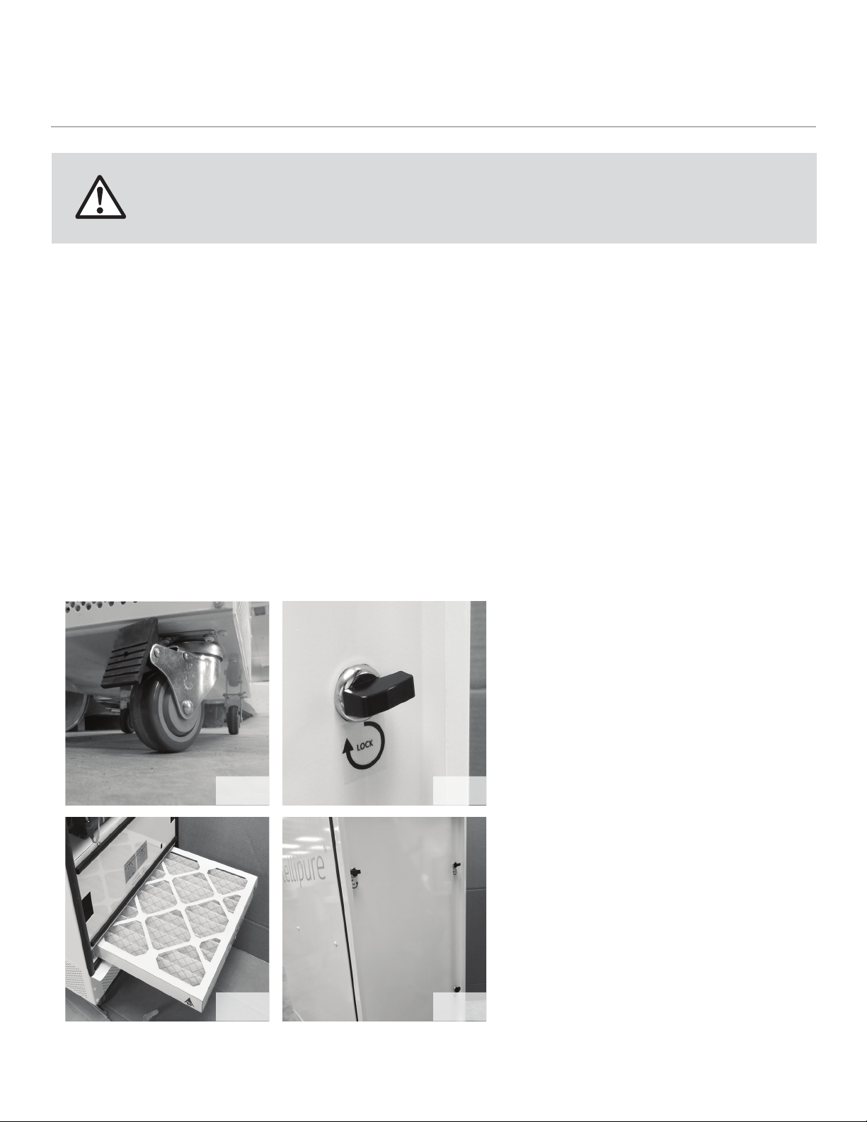
Lock the (2) front wheels to secure the unit. (g-1)
Remove the lter access door by unlocking four quarter turn latches. (g-2).
Filter access door removal may require a rm pull to release.
Slide Prelter out of the lter channel (g-3).
To install a new Prelter, slide the new Prelter into the channel in accordance with the direction of the air ow label. (g-3)
Ensure the Prelter is rmly seated, unit will not turn on without installing Prelter correctly.
Return the lter access door to the unit, (g-4 and g-10) threaded pin shall be positioned into the hole of the control panel to
activate safety switch. The unit will not operate without safety switch activated.
When replacing lters use only Intellipure certied lters. Intellipure lters are
designed for high voltage operation. Use of non-Intellipure lters can be hazardous
to personnel and equipment voiding the warranty.
Fig-4
Fig-2Fig-1
Fig-3

Intellipure 950P
11
VBANK MAIN FILTER REPLACEMENT
- Lock the (2) front wheels to secure the unit. (g-1 on page 10)
- Remove the lter access door by unlocking four quarter turn latches (g-2 on page 10).
- Filter Access Door removal may require a rm pull to release.
- Disconnect the red wire lead from the multiplier (g-5).
- Unlock V-bank lter with a at screw driver or similar tools turning lock cylinder in accordance with labeled direction. (g-6)
Maintenance
Using a rm pull, remove the V-Bank Main Filter
and High Energy Grid Assembly out of the lter
access opening. (g-7)
Inspect and clean the inside of the unit.
Refer to page 12 for proper instructions.
Separate the High Energy Grid from the V-Bank
Main Filter by turning and unlocking three panel
clips (g-8).
Replace the V Bank Main Filter (g-9) and apply
High Energy Grid to the new lter.
Secure the High Energy Grid to the new V Bank
Main Filter by turning and locking three panel clips
(g-8).
Slide the V-Bank Main Filter and High Energy Grid
Assembly back into the unit. Pay attention to the Flow
Direction Arrow on the lter, the arrow should point
towards the Supply/Outlet end of the unit.
Lock V-bank lter with a at screw driver or similar
tools turning lock cylinder in accordance with labeled
direction. (g-6)
Reconnect the High Voltage Lead.
Before returning the door, ensure the Prelter is
rmly seated. The unit will not run if the Prelter is
not installed correctly.
Return the lter access door to the unit, (g-4
and g-10) threaded pin shall be positioned into
the hole of the control panel to engage with safety
switch. The unit will not operate without safety
switch activated.
Fig-5 Fig-6
Fig-7
Fig-9 Fig-10
Fig-8
Always unplug the unit and wait a minimum of 30 seconds before touching the unit.

Intellipure © 2021 All rights reserved.
12
Maintenance
Remove the V-Bank Main Filter and High Energy Grid Assembly
Refer to page 11 for proper instructions.
To clean the wires, use a lint free swab, either dry or moistened with denatured alcohol, clean along the length of each
wire and spring clips.
Clean the inner surfaces of the High Energy Grid material using a lint cloth moistened with denatured alcohol.
Clean the High Energy Grid surface by vacuuming between the wires using a small vacuum attachment or by using a lint
free cloth, either dry or moistened with denatured alcohol. Take care to avoid leaving large bers snagged on the wires,
control grid, or other components of the High Energy Grid.
Make sure that any contaminant that falls to the bottom of the lter unit is removed.
In extreme cases, it may be necessary to remove the wires from the springs attached at each end to the power distribution
bars, thus allowing complete access to the inside of the High Energy Grid assembly for cleaning
as previously described. It is recommended that the manufacturer be contacted for detailed instructions should this step
appear necessary.
Vacuum the bottom of the lter seal plate section and of the lter unit to remove any particles dislodged during cleaning.
Reinstall the High Energy Grid, V-Bank Main Filter and Filter Access Door as previously instructed.
Do not install the High Energy Grid to the V Bank Filter until wires are completely dry.
CLEANING THE UNIT
Depending on contamination level, this procedure should be conducted once a year or during each lter change or if an
electrical problem occurs.
Do not install the High Energy Grid to the V Bank Filter
until wires are completely dry.
Cleaning and user maintenance shall not be made
by children without supervision.

Intellipure 950P
13
Description Part Number
Prelter FT-101-2
V-Bank Main Filter 950/1200_MainFilter
High Energy Grid 950/1200_HEGrid
Multiplier NZ-025
Blower EC-026
120v Power Supply TC80-502
Interlock Switch Single-Pole 2069
Interlock Switch Two-Pole 2009
High Energy Wire WH502
Tungsten wire WH611
Optional Part Number
VOC Filter 2000 VOC Cartridge
Maintenance
PARTS LIST
Order all parts by contacting: Phone No: 315-298-2904 • 1-800-843-3860
Fax No: 315-298-6992
Email: info@intellipure.com
Voltage Adjustment
In order to change the incoming
voltage setting:
Unplug the unit. Remove the front door
(Fig-1).
Remove the electrical panel cover (Fig-2).
Slide voltage switch to appropriate voltage
(Fig-3).
Replace electrical panel cover (Fig-2).
Install front door (Fig-4).
Fig-1
Fig-3 Fig-4
Fig-2

Intellipure © 2021 All rights reserved.
14
Troubleshooting
Service should only be done by a qualied factory trained technician.
For additional troubleshooting assistance contact Intellipure; Monday-Friday, 8am-5pm EST:
Phone No: 315-298-2904 • 1-800-843-3860
Fax No: 315-298-6992
Email: info@intellipure.com
Problem Description Recommended Action
1. Unit will not turn ON.
a. Ensure power cord is plugged in, electrical outlet is
energized.
b. Check fuse located on the bottom of the unit. Check if
fuse was blown.
c. Ensure Pre-lter was installed.
d. Ensure V Bank Main Filter is locked correctly. (g-6)
e. Ensure High Energy Wire is connected (g-5)
2. The unit turns ON but no air blows out Turn o unit and unplug the power, wait 2 minutes and
restart the unit.
3. Unit is ON, but no change in speed Call Intellipure Customer Service (further examination by
trained technician).

Intellipure 950P
15
Troubleshooting
Problem Description Recommended Action
4. Pre-lter indicator is out and Change
pre-lter indicator is illuminated in red Pre-lter needs to be replaced. (Page 13 part number)
5. Main lter indicator is out. Change main lter
indicator is illuminated in red Main lter needs to be replaced. (Page 13 part number)
6. VOC post-lter indicator is out. Change VOC
post-lter indicator is illuminated in red VOC post-lter needs to be replaced. (Page 13 part number)
7. DFS indicator is out and maintenance
indicator is illuminated in red
DFS Technology is turned o or High Energy Grid needs
to be cleaned.

intellipure.com
Other manuals for 950P
1
Table of contents
Other Intellipure Air Cleaner manuals


 owner's manual")


