Intellipure 950P User manual
Installation Manual
950P
PORTABLE AIR CLEANING SYSTEM
2015 #10065

950P
PortableAirCleaningSystem
Installation and Operation Manual
Intellipure’s DDFSTechnology (Disinfecting Filtration System)surpassesallothertypesoffiltration.This
revolutionary technologytrapsmicroorganismssuchasbacteria,moldandviruses,reducesbioburdenandinhibits
microorganism’s growth through Microbiostatic condition, resulting in the most powerful indoor air purification in the
world.
SPECIFICATIONS
•
12gaugealuminumconstruction
•
ButterflyLatchbackdoorforaccess
•
High-memory sponge neoprene door
gasketstoensuredoortofilterseal
•
Aluminum filter track design for 2”
standardprefilterandatrackforHigh
EnergyGridFrame
•
Apolypropylenefinsealonthemainfilter
tracktoeliminatefilterairbypass
•
Designedforcontinuousoperation
•
Op
e
r
a
t
e
s
a
t
120/
22
0
V
,
5
0
/
6
0
H
z
,
4.4
/
2
.
2a
m
p
FEATURES
•
High Air Flow Capacity
–delivershighCFMwithlow
energy consumption
•
Wattage
•
MobileDesign–builtin3.5”safetylockswivelcasters,fullwidth
handle for easy movement
•
Multiple Fan Speeds
–fourfanspeedsforeaseofcontrol
•
99.99% DFS Filtration Efficiency
–downtoasizeof0.007microns
•
IndependentAirflow/DistributionControl–tofacilitate
placement anywhere in the space
•
Patented V-Bank Filter
–increases surface area and provides
higher dust loading capacity
•
Three times longer filter span
–comparedtoconventional
HEPA Filtration –Lower Maintenance Cost
•
HousingDesign
–5052paintedmarinegradealuminum,provides
a100%sealaroundthefilter
•
Ease of Maintenance
–quickreleasefilteraccessfromtheback
sideoftheunit.
•
Optional
V-
bankVOCFilter(70lbs–AdsorbentBlend)
HydratedPhoto
Catalytic Oxidation (HPCO) Odor-TVOC
Cartridge
Low
Medium
High
Turbo
334 m3/hr
660 m3/hr
1000 m3/hr
1500 m3/hr
210 CFM
415 CFM
630 CFM
950 CFM
Low
Medium
High
Turbo
50 watts
90 watts
172 watts
450 watts

950P Portable AirCleaningSystem
950P PortableAirCleaningSystem
#10065
©Intellipure 2015
#10065
3
© Intellipure 2015
Part Number: #10065
Copyright: © 2015 All rights reserved.
Address: Intellipure, Inc.
3420 Maple Ave.
Pulaski, NY 13142
Phone No: 1-315-298-2904
1-800-843-3860
Fax No: 1-315-298-6992
Email: info@Intellipure.com
LIMITED WARRANTY
This one year Limited Warranty applies only to the repair and replacement of any manufactured or supplied part of
this product which, upon inspection by Intellipure authorized personnel, proves to have failed in normal use due to
defects in material or workmanship. A return authorization must be obtained before any product is shipped to the
manufacturer for warranty repair and all transportation charges must be prepaid all work must be performed by a
Intellipure authorized technician. The sole responsibility of Intellipure under this Limited Warranty is, at its sole
discretion, to either repair or replace a duly registered product (or defective part thereof) with the same
comparable model within a reasonable period of time, subject to the following exclusions, limitations, statutory
rights, and warranty claim procedures. This Limited Warranty is exclusive, and Intellipure expressly disclaims all
other or additional warranties, whether written or oral, expressed or implied, including, but not limited to,
warranties of merchantability, workmanship, or fitness for a particular purpose.
Exclusions:
A. This Limited Warranty does not apply, or is void, as to any product or part damaged by (1) accident, misuse,
abuse, or lack of reasonable care or normal maintenance; (2) installation or operation under conditions other
than those recommended by Intellipure; (3) subjection of the product to any but the specified voltage;
(4) servicing or disassembly by unauthorized personnel; (5) defacing the serial number; or (6) modifying the
original factory assembled unit in any way.
B. THIS LIMITED WARRANTY DOES NOT APPLY TO SHIPPING CHARGES FOR PRODUCT SHIPPED TO OR
FROMTHEFACTORYORDESIGNATEDSERVICECENTERINCONNECTIONWITHWARRANTYCLAIMSNOR
DOESITAPPLYTOANYDAMAGESOCCURRINGDURINGSUCHSHIPMENT.
C. This Limited Warranty does not apply to labor for installation, removal, re-installation, and/or travel or shipping
expenses and related expenses.
This Limited Warranty does not apply to replaceable filters.
Limitations:
Intellipure shall not be liable for property, incidental, and/or consequential damages of any kind and, unless otherwise
prescribed by applicable state law, Intellipure shall not be liable for personal injury resulting from malfunctions,
defects, misuse, improper operation or installation, or alteration of an Intellipure product or any part thereof. The
exclusive remedy for a breach of this Limited Warranty is the repair or replacement of the defective product. In no
case, shall liability under any other remedy prescribed by law exceed the purchase price of the product.
Warranty Claim Procedure:
This information is provided as a guide regarding warranty claim procedures for Intellipure air purification systems.
1.
Determine model number from the label on the unit.
2.
For technical support, warranty information, warranty parts or replacement parts, call Intellipure and a
representative will help you troubleshoot and diagnose the problem. Warranty matters involving products sold
through a manufacturer representative should be directed to the appropriate representative.
3.
Important: Do NOT return anything without a Return Authorization.
4.
All returned parts are quality tested. If the returned part is found not to be defective, you may be invoiced for the
new part.
The following is a history of the Instruction Manual
for
950P Portable Air Cleaning System Initial Printing
................ 7/2015

950P Portable AirCleaningSystem
950P PortableAirCleaningSystem
#10065
© Intellipure 2015
#10065
5
© Intellipure 2015
Safety Precautions
SAFETY PRECAUTIONS
Personnel, who will operate this system, or those who will perform maintenance thereon, must be given all
manuals and other instructions regarding safe operation of the filtration system.
This manual contains general recommendations, but specific requirements may apply to individual
installations. Such requirements are outlined in federal, state, and local codes. Compliance with
applicable codes and strict adherence to these installation instructions are the sole responsibility of the user.
This symbol will be used throughout this manual to indicate safety checkpoints.
Failure to heed these warnings and notices may result in damage to the unit and/or
injury or death topersonnel.

950P Portable AirCleaningSystem
950P PortableAirCleaningSystem
#10065
© Intellipure 2015
#10065
7
© Intellipure 2015
TableofContents
Safety Precautions .......................................................................... 5
Receiving and Unpacking................................................................9
Receiving.........................................................................................9
Storage ............................................................................................9
Unpacking and Inspection.............................................................10
System Overview ........................................................................11
Unit Description..............................................................................11
Component Description.................................................................12
Installation Procedures.......................................................13
Power Requirements .....................................................................13
Location Determination..................................................................13
System Operation...........................................................................15
Electrical Connection..................................................................................15
To Turn On the Unit.....................................................................................15
To Turn Off the Unit.....................................................................................15
Maintenance ...................................................................................17
Prefilter Replacement ....................................................................17
VOC PostFilter Replacement........................................................17
V-Bank Main Filter Replacement......................................................18
Cleaning the Unit ...........................................................................19
Parts List........................................................................................20
Troubleshooting............................................................................. 21
DFS Troubleshooting Guide...........................................................22
Figures and Schematics.............................................................1-1
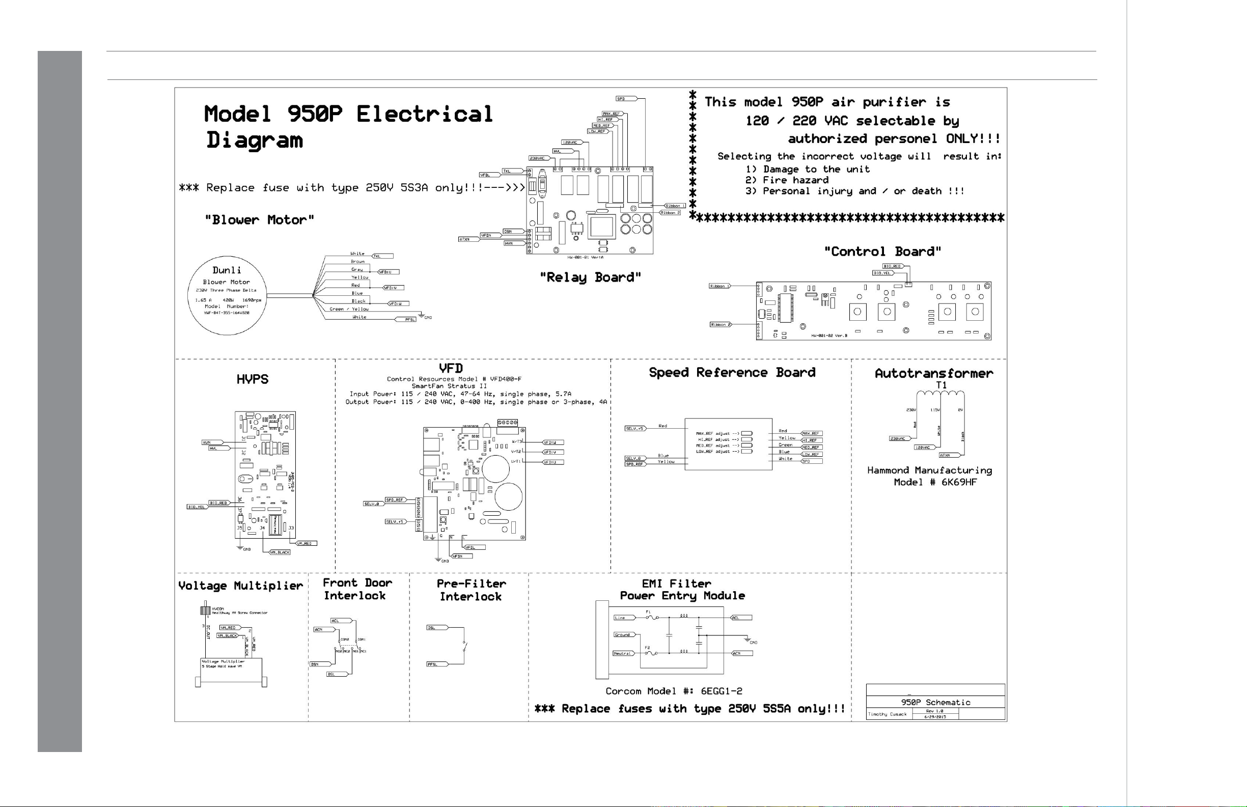
950PSchematic.............................................................................1-1

950P Portable AirCleaningSystem
950P PortableAirCleaningSystem
#10065
© Intellipure 2015
#10065
9
© Intellipure 2015
System Overview
ReceivingandUnpacking
RECEIVING
Your unit has been car fully packed to avoid damage in shipping and storage. Equipment is prepared for
shipment in accordance with the Uniform Freight Classification. It is thoroughly inspected at the factory and
barring damage in transit, should be received in good condition.
When a freight carrier signs the Intellipure bill of lading, the carrier accepts the responsibility for any
subsequent shortages or damage evident or concealed. Inspection by the carrier of damage evident or
concealed must be requested. Evident shortage or damage should be noted on the carrier’s delivery
document before signature of acceptance. Claims must be made against the carrier by the purchaser.
Filtration systems are shipped as fully assembled filter units.
STORAGE
Store it in a dry place protected against moisture, dust, physical damage, weather, corrosion and excessive heat.
Must install the V-Bank Main Filer before running the unit.
For long term storage, unit must be turned on and run at low speed for 8 hours
every 6 months to recondition the capacitors in the VFD.
950P Portable AirCleaningSystem
950P PortableAirCleaningSystem
#10065
10
© Intellipure 2015
#10065
11
© Intellipure 2015
ReceivingandUnpacking System Overview
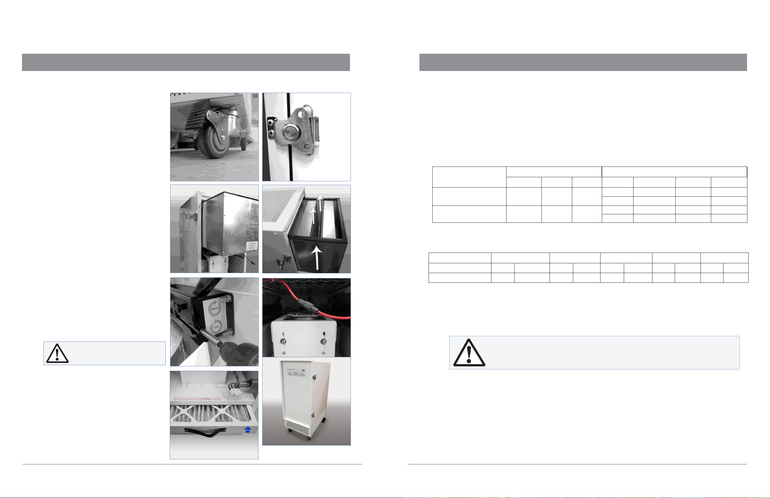
UNPACKING AND INSPECTION
To prevent damage during shipping, the V-
Bank Main Filter and High Energy Grid
Assembly are packaged separately from
the main unit.
To un-crate, remove the strapping, box tops
and additional wrappings around the unit
and V-Bank Main Filter and High Energy
Grid Assembly.
Inspect for damages not previously evident.
Lock the (2) front wheels to secure the
unit. (fig-A)
Remove the Filter Access Door located in
the back of the unit using the four butterfly
latches located on the sides of the unit.
Lift the latch wings (4) and turn
counter-clockwise to open. (fig-B)
Filter Access Door removal may require a
firm pulling effort.
Slide the V-Bank Main Filter and High
Energy Grid Assembly into the unit. Take
note that the labels will be facing outward
with the airflow arrow pointing upwards.
(fig-C) (fig-D)
Using the Magnetic Bit Holder provided,
alternate tightening the left and right
Scissor Locking Mechanisms located near
the motor plate in the filter. (fig-E)
Connect the High Voltage Lead. (fig-F)
Ensure the Prefilter is firmly seated.
The unit will not run if the Prefilter is
not installed correctly. (fig-G)
Return the Filter Access Door. Lift the
latch wings (4) and turn clockwise
to close. (fig-H)
UNIT DESCRIPTION
The 950PAir Cleaning System is a high performance system that utilizes patented award winning
Disinfecting Filtration System technology. DFS technology electrically enhances a low efficiency, high flow,
low-pressure drop filter to high efficiency while retaining the low pressure drop and longer life advantages of
the base filter material. This technology has also been shown to inhibit bacteria growth onthe filter.
The 950PPortable DFS Air Cleaning System is available in the following models:
Model
Power Requirement
Air Flow Capacity
V
Hz
Phase
Low
Medium
High
Turbo
950P
120
50/60
1
334 m3/hr
660 m3/hr
1000 m3/hr
1500 m3/hr
210 CFM
415 CFM
630 CFM
950 CFM
950P
220
50/60
1
334 m3/hr
660 m3/hr
1000 m3/hr
1500 m3/hr
210 CFM
415 CFM
630 CFM
950 CFM
Height
Width
Depth
Weight
Ship Wt
950PUnit
44in
1,118mm
18in
457mm
28in
711mm
155 lb
70 kg
254 lb
116 kg
V-Bank VOC Filter
57in
1,448mm
18in
457mm
28in
711mm
81 lb
37 kg
fig-B
fig-D
fig-F
fig-A
fig-C
fig-E
Do not over-tighten the
Scissor Lock Clamps.
fig-G
fig-H
Please confirm your model number and follow the instructions for that model. The
electrical power requirements for each individual unit are on the data plate label
adjacent to the electrical connections. These requirements supersede all other
inferences to power requirements.

950P Portable AirCleaningSystem
950P PortableAirCleaningSystem
#10065
12
©Intellipure 2015
#10065
13
©Intellipure 2015
SystemOverview
Installation Procedures
COMPONENT DESCRIPTION
The 950P Portable DFS Air Cleaning System integrates the system components into a single, portable unit:
the Prefilter, V-Bank Main Filter and the High Energy Grid are accessible from the back service door. The unit
is also remotely controllable by using a remote control. The fan inlet screen is located on the bottom side of
the unit and provides protection from loose items being drawn into the fan and thus damaging the unit and
the internal components.
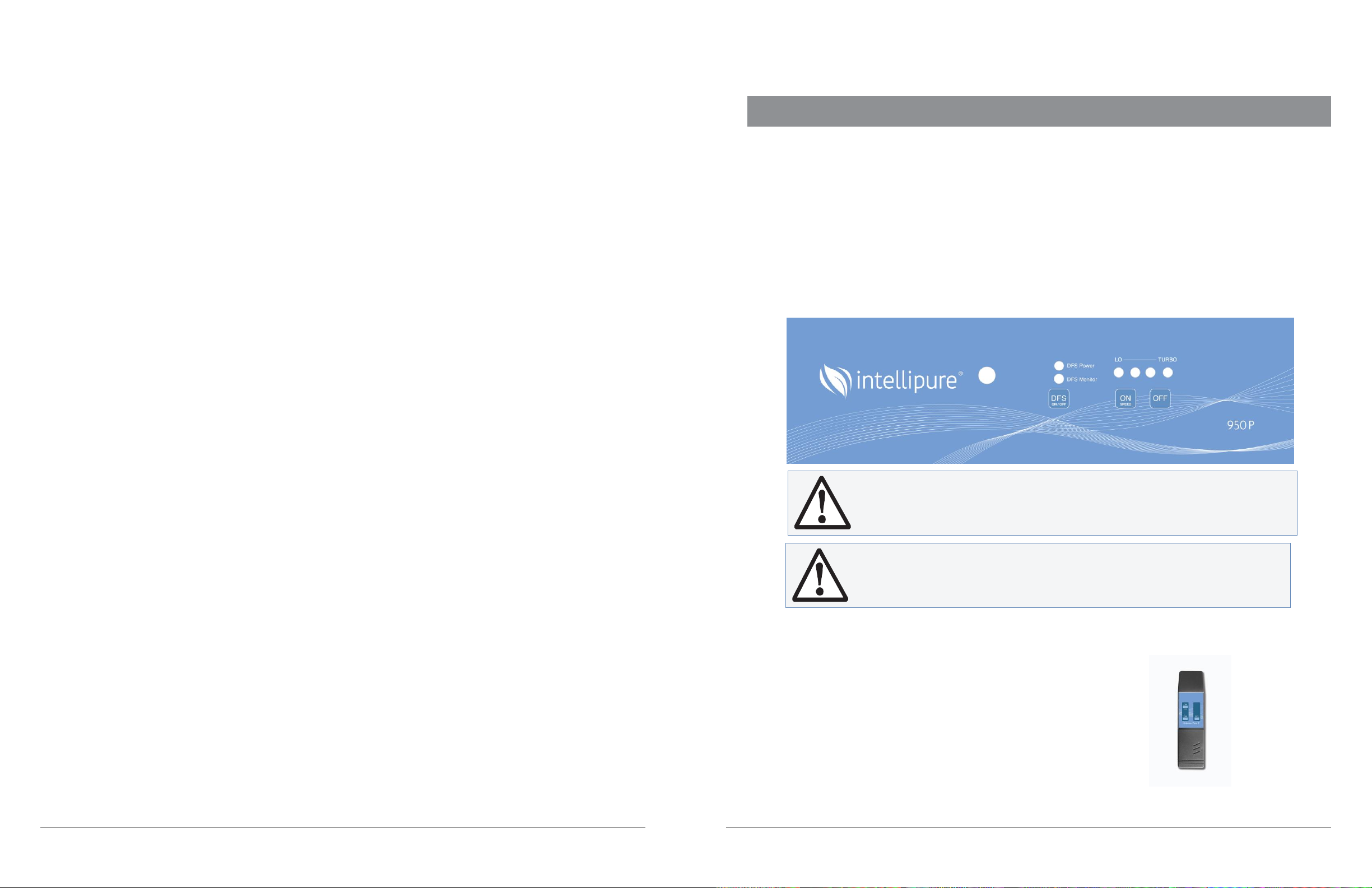
Electrical controls are located on the front of the unit. It consists of the Main Power ON-OFF switch with a
Blue LED to indicate HVPS power status, Blower Speed Status and Blower Speed Control Switch.
Replacement Filters
Efficiency
Replacement Period*
Prefilter
MERV-8 (30% Efficiency)
1-2 times per year
VOC Post Filter
Formaldehyde > 99%
Benzine > 99%
Toluene > 99%
1/2” Filter: 2 times per year
Optional V-Bank: once a year
DFS V-Bank
Main Filter
99.99% Efficient
(down to .007 microns)
once a year
*Replacement period depends on the level of pollution in the environment
POWER REQUIREMENT
The power requirements are as follows:
*Electrical disconnects may also be required - check local electrical codes
Model
Power
FLA
Power Usage
Max Start-up
V
Hz
Phase
AMPS
WATTS
950P
120
50/60
1
4.44
590
950P
220
50/60
1
2.21
560
LOCATION DETERMINATION
The 950P is designed as a portable floor model. Place the air purifier anywhere in the room; being careful
not to block air from “entering” the intake grill, or “exiting” the top grill cover.
Do not place the air purifier where drapes or other objects block airflow.
For best performance, it is recommended to place the air purifier at least two (2) feet from walls and
other obstructions.
Place the unit on a flat and level surface to allow continuous airflow to the bottom intake and out the top
outlet grill.
Do not run power cord under carpeting or near heaters, registers, radiators, stoves or fireplaces. To avoid a
tripping hazard, keep the power cord away from traffic areas.
Never operate the air purifier in areas where combustible gases or vapors are present or any other
flammable materials.
Do not operate unit using an extension cord.
The filter unit will not turn on without the Prefilter installed and firmly seated.
950P Portable AirCleaningSystem
950P PortableAirCleaningSystem
#10065
© Intellipure 2015
#10065
15
© Intellipure 2015
System Operation
ELECTRICAL CONNECTION
Inspect power cord for damage before plugging in.
The outlet must be grounded.
TO TURN ON THE UNIT
Plug the unit in. Turn on the ON/SPEED located on the front of the unit, the power indicator should
illuminate, indicating the power is on, the Blue LEDS indicating blower speed and DFS function should also
come on. (fig-I)
TO TURN OFF THE UNIT
To turn off the unit, simply turn off the main switch located on the front of the unit.
Do not connect power to the unit until the High Energy Grid wires have been
checked for proper connection. (Refer to page 10)
fig-I
LO
TURBO
®
950P REMOTE
Each unit is also equipped with a Remote Control. (fig-J)
The Remote has 3 buttons:
fig-J
ON/SPEED Turns the unit on and controls the speed of the fan.
OFF Turns the unit off
FS Turns the FS on andoff
®
Disconnect power to the unit before servicing. Moving Parts inside.
Wait 30 seconds after turning the unit off before opening the Filter Access
Door.

950P Portable AirCleaningSystem
950P PortableAirCleaningSystem
#10065
© Intellipure 2015
#10065
17
© Intellipure 2015
Maintenance
PREFILTER REPLACEMENT
Lock the (2) front wheels to secure the unit. (fig-1)
Remove the Filter Access Door located in the back of the unit using the four butterfly latches located on the
sides of the unit. Lift the latch wings (4) and turn counter-clockwise to open. (fig-2)
Filter Access Door removal may require a firm pulling effort.
Simply slide the Prefilter out of the filter channel located in the bottom of the unit. (fig-3)
To install a new Prefilter, slide the Prefilter back in the channel. Pay attention to the Flow Direction Arrow on
the Prefilter, the arrow should point upwards towards the Supply/Outlet End of the unit. (fig-3)
Ensure the Prefilter is firmly seated. The unit will not run if the Prefilter is not installed correctly.
Return the Filter Access Door. Lift the latch wings (4) and turn clockwise to close. (fig-2)
VOC POST FILTER REPLACEMENT
Lock the (2) front wheels to secure
the unit. (fig-1)
Remove the Filter Access Door located in
the back of the unit using the four butterfly
latches located on the sides of the unit. Lift
the latch wings (4) and turn
counter-clockwise to open. (fig-2)
Filter Access Door removal may require a
firm pulling effort.
Simply slide the VOC Post Filter out of
channel located in the top of the unit. (fig-4)
To install a new VOC Post Filter, slide
the VOC Post Filter back in the channel.
Return the Filter Access Door. Lift the
latch wings (4) and turn clockwise
to close. (fig-2)
When replacing filters use only Intellipure certified filters. Intellipure filters are
designed for high voltage operation. Use of non-Intellipure filters can behazardous
to personnel and equipment voiding the warranty.
Always unplug the unit and wait a minimum of 30 seconds before
touching the unit.
fig-2
fig-3
fig-4
fig-1

950P Portable AirCleaningSystem
950P PortableAirCleaningSystem
#10065
18
© Intellipure 2015
#10065
19
© Intellipure 2015
fig-6
fig-5
Maintenance
Maintenance
V-
BANK MAIN FILTER REPLACEMENT
Lock the (2) front wheels to secure the unit. (fig-1)
Remove the Filter Access Door located in the back of the unit using the four butterfly latches located on the
sides of the unit. Lift the latch wings (4) and turn counter-clockwise to open. (fig-2)
Filter Access Door removal may require a firm pulling effort.
Using the Magnetic Bit Holder provided, alternate loosening the left and right Scissor Locking Mechanisms
located near the motor plate in the filter. Make sure the Scissor Locking Mechanisms are fully opened. (fig-5)
Disconnect the High Voltage Lead from the High Energy Grid. (fig-6)
Using a firm pull, remove the V-Bank Main Filter and High Energy Grid Assembly out of the filter access
opening. (fig-7)
Inspect and clean the inside of the unit.
Refer to page 19 for proper instructions.
Separate the High Energy Grid from the
V-Bank Main Filter by removing the
six screws (4 corners and 2 in the center)
in the V-Bank Main Filter. (fig-8)
Replace the V-Bank Main Filter.
Secure the V-Bank Main Filter to the bottom
of the High Energy Grid by using the
six screws (4 corners and 2 in the center)
in the V-Bank Main Filter.
Slide the V-Bank Main Filter and HighEnergy
Grid Assembly back into the unit. Pay
attention to the Flow Direction Arrow on
the Prefilter, the arrow should point
upwards towards the Supply/Outlet end
of the unit. (fig-9)
Using the Magnetic Bit Holder provided,
alternate tightening the left and right
Scissor Locking Mechanisms located
near the motor plate in the filter.
CLEANING THEUNIT
Depending on contamination level, this procedure should be conducted about once a year or during each
filter change or if an electrical problem occurs.
Remove the V-Bank Main Filter and High Energy Grid Assembly
Refer to page 18 for proper instructions.
To clean the wires, use a fiber free swab, either dry or moistened with distilled or deionized water, clean
along the length of each wire, spring clip, and ceramic insulator.
Clean the inner surfaces of the High Energy Grid material using a lint cloth moistened with distilled or
deionized water.
Clean the High Energy Grid surface by vacuuming between the wires using a small vacuum attachment or
by using a lint free cloth, either dry or moistened with distilled or deionized water. Take care to avoid leaving
large fibers snagged on the wires, control grid, or other components of the High Energy Grid.
Make sure that any contaminant that falls to the bottom of the filter unit is removed.
In extreme cases, it may be necessary to remove the wires from the springs attached at each end to the power
distribution bars, thus allowing complete access to the inside of the High Energy Grid assembly for cleaning
as previously described. It is recommended that the manufacturer be contacted for detailed instructions
should this step appear necessary.
Vacuum the bottom of the filter seal plate section and of the filter unit to remove any particles dislodged during
cleaning. Reinstall the High Energy Grid, V-Bank Main Filter and Filter Access Door as previously instructed.
Reconnect the High Voltage Lead.
Ensure the Prefilter is firmly seated.
The unit will not run if the Prefilter is
not installed correctly.
Return the Filter Access Door. Lift the
latch wings (4) and turn clockwise
to close. (fig-10)
fig-9
fig-10
Do not over-tighten the
Scissor Lock Clamps.
Do not use alcohol or cleaners that may damage acrylics, plastics or aluminum.
fig-7
fig-8

950P Portable AirCleaningSystem
950P PortableAirCleaningSystem
#10065
20
© Intellipure 2015
#10065
21
© Intellipure 2015
Maintenance
Troubleshooting
PARTS LIST
Intellipure recommends that the following spare parts be available on-site at all times.
Order all parts by contacting:
Phone No: 1-315-298-2904
1-800-843-3860
Fax No: 1-315-298-6992
Email: info@Intellipure.com
For additional troubleshooting assistance refer to the DDFS Troubleshooting Guide on the following page or
contact Intellipure International:
Phone No: 1-315-298-2904
1-800-843-3860
Fax No: 1-315-298-6992
Email: info@Intellipure.com
Service should only be done by a qualified factory trained technician.
Problem Description
Recommended Action
Blue LED (FS) is OFF - Fan is running
1.
Check the High Energy Grid for broken, loose
or disconnected wires and debris. If the
problem persists then refer to the
FS Troubleshooting Guide.
2.
If the problem persists, then call for assistance.
Fan motor not running
1.
Check whether the unit is running on the required
supply voltage and confirm the status of the fuses.
2.
If problem persists, then check for disconnected
wires or connectors inside the unit including all low
voltage control connections.
3.
If the problem persists, then call for assistance.
Blue LED (FS) is OFF - Fan is not running
1.
Check whether the unit is running on the required
supply voltage and confirm the status of the fuses.
2.
If the problem persists, check the prefilter and
prefilter safety interlock.
3.
If the problem persists, then call for assistance
Description
Part Number
Prefilter
FT-101-2
V-Bank Main Filter
1200-VB-92
1/2” Carbon Post Filter
950P carbon filter
High Energy Grid
TC-019
High Energy Grid Wires
NZ-023
High Energy Voltage Lead Wires
NZ-026
1/2” S.S. Spring
NZ-004
Airdecon Pure 2 H.V. Extension Cable
950P HV ext cable
230V 3 Prong Cord
10-916
Standoff
7047
Multiplier
NZ-025
355-230-3ph motor
4065
115/240v VFD
EC-083
120v Power Supply
2010
230-120 Step-Down Transformer
EC-033
Electronics Assembly:
Relay, Ribbon, Control Panel
LED Light Wires
4045
EMI Filter w/ Fuse 5amp
NZ-033
Interlock Switch Single-Pole
2034
Interlock Switch Two-Pole
2009
Airdecon Pure 2 Remote
4051
2-7/8 Magnetic Bit Holder
HA-115
Optional
Part Number
Airdecon Pure 2 VOC Filter Assembly
950P-VOC
1200- VB VOC
1200-VB-VOC

950P Portable AirCleaningSystem
950P PortableAirCleaningSystem
#10065
22
© Intellipure 2015
#10065
23
© Intellipure 2015
Troubleshooting
Troubleshooting
DFS TROUBLESHOOTING GUIDE
Refer to pages 17 and 18 to view figures
Symptom: The unit has been turned on but the High Voltage Power Supply Indicator Light (DFS) is OFF
Probable cause #1: Short in High Energy Grid (foreign debris, loose wires, loose electrical connection)
Confirmation:
Step 1: Disconnect power to unit and lock the (2) front wheels to secure the unit. (fig-1)
Step 2: Remove the Filter Access Door located in the back of the unit using the four butterfly latches
located on the sides of the unit. Lift the latch wings (4) and turn counter-clockwise to open. (fig-2)
Step 3: Disconnect the High Voltage Lead from the High Energy Grid. (fig-6)
Step 4: Safely secure the male end of the High Voltage Lead to ensure that the High Voltage Lead cannot
contact the blower wheel.
Step 5: The following steps should be done with extreme care and the person(s) performing this
test should ensure that unauthorized personnel cannot come in contact with dangerous moving
parts and high voltages.
Defeat Safety Interlock: Ensure the Prefilter is firmly seated. The unit will not run if the Prefilter is not
installed correctly.
Step 6: Return power to the unit and put the unit into run mode. Observe the status of the High Voltage
Power Supply Indicator Light (DFS). If the light is now functioning the problem is in the High
Energy Grid.
Disconnect power to the unit and follow these steps:
(A)
Using the Magnetic Bit Holder provided, alternate loosening the left and right Scissor
Locking Mechanisms located near the motor plate in the filter. Make sure the Scissor Locking
Mechanisms are fully opened. (fig-5)
(B)
Ensure the High Voltage Lead is disconnected from the High Energy Grid. (fig-6)
(C)
Using a firm pull, remove the V-Bank Main Filter and High Energy Grid Assembly out of the
filter access opening. (fig-7)
(D)
Separate the High Energy Grid from the V-Bank Main Filter by removing the six screws (4
corners and 2 in the center) in the V-Bank Main Filter. (fig-8)
(E)
Inspect the High Energy Grid and its wires, they should be free from debris and evenly
tensioned. Loose wires can cause arcing or cause the protection circuit to trip.
(F)
Inspect the “V” sections of the V-Bank Main Filter and ensure that it is free of metal debris,
excess dirt or hair etc…
(G)
Secure the V-Bank Main Filter to the High Energy Grid by using the six screws (4 corners
and 2 in the center) in the V-Bank Main Filter.
(H)
Stand the V-Bank Main Filter and High Energy Grid Assembly up and inspect the gasket on
the seal side of the Assembly. Replace the gasket if it is damaged
DFS TROUBLESHOOTING GUIDE CONT.
(I)
Slide the V-Bank Main Filter and HighEnergyGridAssemblybackintotheunit.Pay attention to
the Flow Direction Arrow on the Prefilter, the arrow should point upwards towards the
Supply/Outlet end of the unit. (fig-9)
(J)
Tighten the right and left Scissor Locking Mechanism.
(K)
Repeat Step 5 from aboveand place the unit in runmode to confirmthe problemhas been resolved.
Conclusion: If the High Voltage Power Supply Indicator Light stays off this indicates a faulty Voltage
Multiplier. Disconnect power from the unit and replace the Voltage Multiplier. Repeat Step 5
from above and place the unit in run mode to confirm the problem has been resolved.
Probable Cause #2: Faulty Voltage Multiplier / Faulty High Voltage Power Supply (DFS)
Confirmation:
Step 1: Disconnect power to unit
Step 2: Open the Electrical Panel located behind the front panel of the unit. You will need to remove the
(14) screws holding the front panel in place.
Step 3: Locate the Voltage Multiplier above the electrical components on the left side. The Voltage
Multiplier is a gray, rectangular device with red and black wires at one end and a single red wire
at the opposite end. (fig-11)
Step 4: Disconnect the red wire of the Voltage Multiplier from the “J3” terminal of the High Voltage
Power Supply (HVPS). Stay clear of this terminal while testing and Do Not attempt to
re-connect the terminal with power applied to the unit.
Step 5: Re-connect power to the unit
Step 6: Place the unit in “run” mode and observe the status of the High Voltage Power Supply Indicator
Light (HVPS1)
Conclusion: If the High Voltage Power Supply Indicator Light stays off with no Voltage Multiplier attached
there is a fault in the High Voltage Power Supply. Disconnect power from the unit and
replace the High Voltage Power Supply.
If the High Voltage Power Supply
indicator light is on with no Voltage Multiplier attached the fault is
either in the High Energy Grid or in the Voltage Multiplier.
Variable Frequency Drive
High Voltage Power
Service should only be done by a qualified factory trained technician.
Voltage Multiplier
fig-11
950P Portable DFS Air Cleaning System
950P-220
#10065
©Intellipure 2015
1-1
950P

©Intellipure 2015 #10065
Other manuals for 950P
1
Table of contents
Other Intellipure Air Cleaner manuals


