eisfink varithek acs 1500 d3 User manual
Bedienungsanleitung
Preliminary Draft
Air Cleaning System ACS
Type: acs 1500d3 – 32A
Please read instructions carefully before use
Image acs 1500d3
Varithek acs 1500 d3
- The product innovation by Eisfink and Rieber

Page 2
Air Cleaning System ACS
The Air Cleaning System ACS conforms to the EMC Directive 2004/108/EEC and the Low Voltage
Directive 2006/95/EC. Copies of the corresponding conformity declarations can be obtained from
the manufacturer.
Image acs 1500d3
We reserve the right to make technical changes!
Due to continuous further development, illustrations, functional steps and technical data may deviate
slightly.
Manufacturer's address
EISFINK MAX MAIER GMBH & CO.KG
Im Werkzentrum Weststadt
Rheinlandstr. 10
D 71636 Ludwigsburg, Germany
Phone: +49/7141/479-0
Fax: +49/7141/479-299
http://www.eisfink.de or http://www.varithek.de
Date: 17/02/2011

Page 3
Air Cleaning System ACS
Contents
1 General 4
1.1 Preliminary remarks 4
1.2 Symbols for user instructions 4
1.3 Laws, standards, directives 5
1.4 Scope of supply 5
1.5 Instructions for operator 5
1.6 Warranty 5
2 Safety 6
2.1 Use as per specifications 6
2.2 Misuse 6
3 Description of product 7
3.1 Basic dimensions and technical data 7
3.2 General equipment 7a
3.3 Electrical equipment 8
3.4 varithek
®
functional elements 8
4 Transport / Assembly / Installation 9
4.1 Mechanical 9
4.2 Electrical 9
5 Operation 10
5.1 General safety instructions 10
5.2 Commissioning ACS 10
5.3 Commissioning varithek
®
cooking components 11 + 11a
6 Cleaning and maintenance 12
6.1 General 12
6.2 First clean, regular cleaning and maintenance of ACS module 12 - 14
6.3 Regular cleaning and maintenance of varithek
®
cooking components 15
7 End of operation and interruption of operation 16
8 Faults and possible causes 17
9 Circuit diagram 18
10 Wiring diagram 19
Page 4
Air Cleaning System ACS
1 General
1.1 Preliminary remarks
These operating instructions were specifically prepared for the staff operating the Air Cleaning
System ACS. They contain important information on installation, assembly, operation, safety and
cleaning of the system.
These operating instructions are valid for all available ACS modules with edge extraction.
For the relevant design of the ACS modules, refer to the shipping and order documentation or the
specifications on the rating plate.
Before first commissioning, please read these operating instructions carefully and ensure that
all users read these operating instructions before using the unit. The
operating instructions must be available at the place of installation at all times.
This unit is not intended for use by persons with limited physical, sensory or mental abilities or
inexperienced and/or unskilled persons (including children), unless such persons are supervised by
another person who is responsible for their safety or were instructed by this person on how to use
the unit.
Children should be supervised to ensure they won't play with the unit.
1.2 Symbols for user instructions
Warning!
Identifies a possibly dangerous situation. Non-observance may result in injuries and/or material
damage.
Warning, hot surface!
Identifies a possibly dangerous situation caused by hot surfaces. Non-observance may result in
burns and/or material damage.
Tip!
Identifies user tips for optimum use of the unit and other useful information.

Page 5
Air Cleaning System ACS
1.3 Laws, standards, directives
During design and manufacturing of the unit, the requirements of the following directives and regulations
were complied with:
•Directive 93/43/EEC: Hygiene Directive
•Directive 2006/95/EEC: Low Voltage Directive
•Directive 2004/108/EEC: EMC Directive
•DIN EN 60335-1: Household and similar electrical appliances - Safety -
•DIN EN 60335-2-36
•DIN EN 60335-2-99
•DIN 18869-1
•DIN 18869-5
•DIN EN 50366 Electromagnetic fields
TPS test programme for large kitchen units: Ventilation equipment of commercial kitchens
1.4 Scope of supply
•For the scope of supply and the design of the elements, refer to the enclosed shipping papers.
•Remove the packaging of the elements and dispose of the packaging material properly and in an
environmentally compatible way.
•Check the elements for any transport damage. Document any damage on the carrier's consignment
note and report the damage to your supplier immediately.
1.5 Instructions for operator
As the operator, you are responsible for:
•ensuring that all elements of the Air Cleaning System are used properly as per the relevant
specifications,
•compliance with the safety regulations and safety instructions,
•instructing the operating staff and ensuring that these persons read and understand the operating
instructions,
•ensuring that all safety equipment works properly,
•for providing appropriate safety and working clothes and
•ensuring appropriate working conditions.
1.6 Warranty
Generally, the "General Terms and Conditions" of EISFINK MAX MAIER GmbH & CO.KG shall apply. In
these terms and conditions, the conditions of warranty claims are specified in detail.
Warranty claims will only be accepted if the unit is used as per specifications (see following section
"Safety").

Page 6
Air Cleaning System ACS
2 Safety
2.1 Use as per specifications
The Air Cleaning System ACS is an extraction system which, in combination with adequate and
dimensionally matching cooking units, e.g. varithek
®
cooking components, is used for removing fumes and
vapours at any location. For proper use of the installed cooking units, refer to the relevant operating
instructions.
An Air Cleaning System is no substitute for a ventilation system as required by VDI 2052.
The following functions can be performed with the ACS:
•Frying, grilling, cooking, woking and deep-frying in combination with adequate and dimensionally
matching cooking units, e.g. varithek
®
cooking components.
Any other use shall be considered as a misuse and can have non-foreseeable consequences.
2.2 Misuse
Misuse which may have dangerous consequences includes in particular:
•Flambéing
•Use of gas cooking units
•Transporting of persons on mobile ACS modules
•Use of the installed cooking equipment for heating of rooms or any objects other than food.
•Use of other devices which do not have the correct dimensions for installation in the Air Cleaning
System. Such devices might reduce the functionality of the ACS.
Warning!
Never leave the operating unit unattended!
The safety and operating information provided in these operating instructions shall not replace the
necessity for compliance with the legal and Employers' Liability Insurance Associations' regulations
(e.g. BGR 111 – Working in kitchen operations). These requirements must be met in addition to the
instructions given in these operating instructions.

Page 7
Air Cleaning System ACS
3 Description of product
The Air Cleaning System ACS is an extraction system which, in combination with adequate and
dimensionally matching cooking units, e.g. varithek
®
cooking components, is used for removing fumes and
vapours at any location. For proper use of the installed cooking units, refer to the relevant operating
instructions.
By replacing elements, the user can respond flexibly to special requirements and requests.
3.1 Basic dimensions and technical data
Dimensions / model ACS 1500 d3
Width 1,500 mm
Depth with front cover closed 740 mm
Total height including splash protection 1,100 mm
Height without splash protection 900 mm
Height of carcass without casters
and splash protection 780 mm
Connected power 3N AC 230V / 400 V, 50 Hz, 32 A, max. 22 KW
Electrical connection 2 m cable, CEE connector 3x 32A L1 / L2 / L3 / N / PE
IP protection IP X4
Weight 130 kg
Pressure of separator 360 Pa
Volumetric flow rate 1,150 m³/h
3.2 General equipment
Design variants of ACS:
•Mobile design: features 4 steering casters, caster diameter 80 mm.
The steering casters on the operator's side feature locking brakes.
•Stationary design: features 4 cast iron feet.
Standard equipment and components:
As standard, the ACS module features 4 steering casters of chrome nickel steel CNS 18/10 (WN 1.4301),
two of them (on operator's side) equipped with locking brakes. Also included: 3-part, removable splash
protection of chrome nickel steel CNS 18/10 (WN 1.4301), two cyclone filters (E-cyclone) made of coated
aluminium, two divided grease collection pans, two fan motor units, four smell filter double cartridges with
zeolite filling and two wrenches.
Page 7a
Air Cleaning System ACS
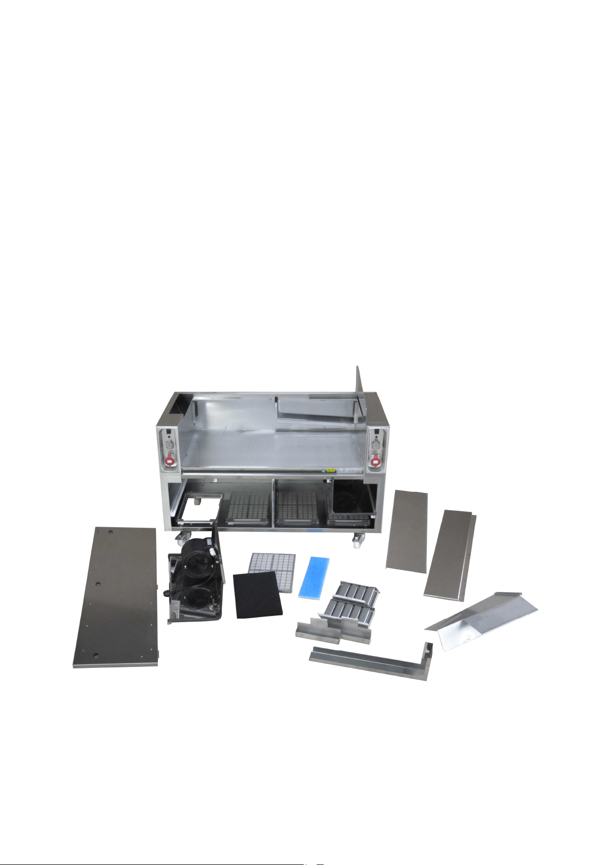
1: body of CNS 18/10 with built-in
control panel left + right
2: Inspection cover, removable
3: 2 fan motor units with connection cable
4: 4 activated carbon filters
5: 4 smell filter double cartridges
6: -optionally- fabric filter
7: 2 grease collection pans (2 parts)
8: 2 cyclone filters (E-cyclone, 2 parts)
9: Rear wall installation niche, removable
10: Splash protection middle part, removable
11: 2 splash protection side parts, removable
12: 2 intake duct, removable from rear side
Image acs 1500d3
1
9
1
9
6
8
3
4
12
11
7
5
10
2

Page 8
Air Cleaning System ACS
3.3 Electrical equipment
Model Number of sockets
ACS 1500 d3 2 x 230 V sockets with earthing contact
2 x 400 V-CEE sockets
Electrical consumers Power consumption
Fan motor unit max. 230 V ACS 1100 d3: 2 x 440 W
varithek
®
grill gp 3500sp max. 230 V 3.5 kW
varithek
®
grill gp-b 3500(hv) max. 230 V 3.5 kW
varithek
®
induction hob ik/iw 3500 max. 230 V 3.5 kW
varithek
®
induction hob ik/iw 5000 max. 400 V 5.0 kW
varithek
®
ceran hob ck 3400 max. 230 V 3.4 kW
varithek
®
grill gp 5500(sp) max. 400 V 4.6 kW
varithek
®
grill gp 9000(sp) max. 400 V 6.6 kW
varithek
®
grill gp 11000(sp) max. 400 V 8.1 kW
3.4 varithek
®
cooking elements
Element Use
grill 1/1-gp 3500 (sp) for grilling and frying
400-gp 5500 (sp)
600-gp 9000 (sp)
800-gp 11000 (sp)
grill 1/1-gp-b 3500 for grilling and stewing
induction hob ik/iw 3500 / 5000 for cooking and frying with induction energy
ceran hob ck 3400 for cooking and frying with radiation energy

Page 9
Air Cleaning System ACS
4 Transport / Assembly / Installation
During assembly and installation, the applicable electro-technical, fire protection and local building control
regulations shall be complied with. For a perfect function of the unit and operational safety, proper
installation, operation and maintenance in accordance with these operating instructions are required.
Warning! Risk of material damage.
If the ACS module is moved to another place, the locking brakes on the steering casters must be
released. All electrical couplings must be disconnected as well as any mechanical fixtures to
adjacent furniture. Always ensure that the connection cable is secured such (e.g. using adhesive
tape) that it cannot get under the steering casters.
4.1 Mechanical
Move the ACS module to the intended place of installation. This place must be level and clean.
A minimum distance of 5 cm must be kept from combustible material, except for the electric supply cable of
the ACS.
When transporting the ACS module, do not move the unit over obstacles lying on or projecting
from the floor, otherwise the connection cable on the underside of the unit might be damaged.
Also ensure that the extraction module is in a horizontal position. To that end, the steering casters are
adjustable in height. To adjust the height of the casters, loosen the locknut using the supplied wrenches and
turn the axle of the corresponding caster. To reduce the height of the extraction module, turn the axle in a
clockwise direction, to increase the height, turn it in an anticlockwise direction.
To adjust the extraction unit properly, use a level. As soon as you have adjusted it to the correct height,
tighten the locknut again using the supplied wrenches.
To fix the unit at the place of installation, press down the locking brakes on the steering casters on the
operating side of the unit.
4.2 Electrical
Before commissioning, check the mains voltage and type of current. Make sure they match the
specifications on the rating plate.
The requirements of DIN / VDE 0100 ff. as well as the technical connection requirements of the local power
utility must be met.
The unit is provided with a connection cable with CEE connector for connection to an existing socket.
Ensure that an appropriate fuse/circuit breaker is provided for the 400 V / 32 A CEE socket (not included in
scope of supply). We expressly point out that the units may be damaged if the neutral conductor is
interrupted. The socket outlet must be easily accessible so that the unit can be disconnected from power
supply at any time. As a unit of protection class 1, it must always be connected to the earth conductor. The
cable must be routed such that it cannot be squeezed.
If you are not sure if all requirements are met, consult an electrician.
If the connection cable of this unit is damaged, it must be replaced by the manufacturer, its customer
service or a qualified electrician, to avoid any risks.
Equipotential bonding - connection for existing additional equipotential bonding protection system.
This sign is fixed to the front and the underside of the bottom of the unit and indicates the
position of the terminal.

Page 10
Air Cleaning System ACS
5. Operation
5.1 General safety instructions
Warning! Risk of tilting and falling over!
When moving the ACS module across uneven surfaces, uncontrolled movements must be
expected. Do not let go of the unit while transporting it.
Warning! Danger of jamming!
When moving the unit to another location, ensure that no body parts are caught between the ACS
module and adjacent furniture, in particular when pushing the unit into a niche. After placing the
module at the required place, lock the casters to avoid uncontrolled rolling away.
5.2 Commissioning ACS
The extraction module was checked after manufacturing for proper function. Before commissioning the unit
for the first time, please ensure that there are no packaging residues or other objects inside the case or the
side air ducts and that the filters and grease collection pan are installed at the correct place.
The ACS module may never be operated without the filter components and grease collection pan
installed and placed correctly..
The extraction module is commissioned by plugging the connection cable in a correctly installed and fused
400 V CEE socket. As soon as the unit is connected to power supply, the indicator light (1) will be green.
Now, the sockets installed in the control panel are powered.
To start the system, press the circulating air On/Off switch which is positioned on the left and/or right side. If
you switch on the circulating air system on both sides, the grease and smell loaded vapours are sucked into
the intake duct and the filter system from three sides (left, right and rear).
We recommend leaving the circulating air system on for 10 more minutes once you are finished
with cooking to prevent the vapours (which rise due to the residual heat) from spreading into the
environment.
Before opening the inspection cover of the ACS module, both Ventilation On/Off switches must be
switched off and the mains plug must be disconnected from power supply. Otherwise, there is the
risk of injury from the fan of the extraction unit.
Control panel
1: Circulating air on/off switch
2: Circulating air indicator light
3: 230 V socket
4: 400 V CEE outlet

Page 11
Air Cleaning System ACS
5.3 Commissioning of varithek
®
cooking components
Ensure that the exhaust air ducts at the inner front of the installation niche are fixed properly.
If varithek
®
cooking components are used, first place the system carriers in the installation niche of the
extraction module.
Then insert the varithek
®
cooking unit in the system carrier.
Warning! Danger of jamming!
When inserting the cooking unit, take care to prevent body parts from being caught. Also ensure
that the power cables of the varithek
®
cooking elements are not jammed!
Acs 1500d3 easy-clean
suitable for operation with three thermal devices (varithek
®
GN 1/1) with the corresponding varithek
®
system
carrier ast 255 or ast 155, a grill plate with a width of up to 800mm (e.g. varithek 800 gp 1100sp) and
another thermal device or three varithek
®
400 devices (no system carrier required).
Never insert 400V + 230V units on the left or right side of a switch panel at the same time.
Comply with the relevant operating instructions of the varithek
®
components.
Warning! Risk of burns and jamming!
If using cooking, frying and deep-frying units, there is the risk of burns/injury due to hot surfaces.
This risk will even be present after these units are switched of as the hot surfaces may cool down
slowly.
Allow the cooking units to cool down completely before removing the cooking equipment and
cleaning the ACS.
If the ACS module is to be moved to another location after use, please remove the installed
cooking equipment or secure it properly so that it cannot move during transport.

Page 11a
In case of varithek
®
grill plates and grill-roasters in system carrier, use the supplied fixing clamp
which prevents the grill plate from slipping out of the system carrier.
Deep-fryer in ACS Air Cleaning System
If a deep-fryer FT 6 is used in ACS 1500 d3, it must be installed in a varithek
®
tabletop system
carrier AST 255 and fixed with an insertion mask EM AST FT 6.
Only one deep-fryer may be used in the ACS.
The general filter and grease rules must be followed, otherwise the efficiency of the filter systems
is affected.
Risk of explosion! Risk of burns!
Never pour water in the deep-fryer as long as it is filled with grease / oil - neither when the fryer is
hot nor when it is cold.
There must not be any water tapping points or devices containing liquids, e.g. water baths or
kettles, near deep-fryers. A minimum distance of 90cm must be kept in any case.
Page 12
Air Cleaning System ACS
6 Cleaning and maintenance
6.1 General
Cleaning is particularly important for equipment and units used for preparing and/or serving food. For this
reason, the operating staff must be familiar with the section "Cleaning and maintenance" in order to ensure
hygienic conditions.
Warning! Risk of burns, cutting and jamming!
When cleaning the system, use gloves suitable for cleaning; skin which is softened by cleaning
agents may be injured at metal edges.
Allow the cooking units to cool down completely before removing the cooking equipment and
cleaning the ACS. (grill plate approx. 30 min.)
Warning! Material damage.
Do not use any cleaning agents containing acids. Cleaning agents must not contain any
hydrochloric acid or hydrofluoric acid, as these acids might result in decolouration of the surfaces
and even corrosion. Do not use any sharp-edged objects for cleaning.
Warning!
Before cleaning and servicing the unit unplug the unit in all circumstances!
Warning!
Do not clean with a water jet cleaner.
Cleaning agents
Only use the specified cleaning agents and little water for cleaning the casing parts. Use the
cleaning agents as per the relevant manufacturer's instructions. Tenacious dirt may be cleaned
using a soft plastic fibre, for example. Then, rinse with clean water.
6.2 First clean, regular cleaning and maintenance of ACS module
Before first commissioning, the unit must be cleaned thoroughly to remove any packaging or transport
residues.
The ACS and its components must be checked for dirt accumulation daily and cleaned, as necessary.
We recommend cleaning the ACS module each time after use.
Before cleaning, the units must be disconnected from electric power supply. Components (plastic
parts) which might not be compatible with the cleaning agent used must be protected. Before
cleaning, the splash protection and the side cover must be removed. The units in the niche may
remain in their place.
Use a soft cloth and water for cleaning the casing components; the water may be mixed with a mild, grease-
solving but scouring-agent-free cleaning agent. Grease and grease-bound pigment dirt can be removed
easily using a universal cleaning agent, neutral or alkaline cleaning agent.
Tenacious grease (resinified oil and grease) on casing components may be removed using solvent-
containing cleaning agents and scouring-agent-free emulsions.
The foldable casing parts, the connection points of the elements, as well as lower edges and indentations,
must be cleaned with particular care. At these places, food residues and dirt may accumulate.

Page 13
Air Cleaning System ACS
Cleaning of filter area
Ensure that the ACS module is disconnected from power supply.
To clean the filter area, open the inspection flap using a wide flat-blade screwdriver by turning the locking
buttons by 90°in clockwise direction.
Warning! Risk of injury!
Never open the flap of the extraction module while the unit is switched on! Risk of injury from
extraction unit fan. Always disconnect the unit from the power supply. If the unit is not cleaned as
per the following instructions, there is the risk of fire.
Cyclone filter (E-cyclone) (grease filter) / grease collection pan
The cyclone filters are installed in the right + left side pan. Take them by the handle fixed on the upper side,
lift them up and take them out of the unit. Then, you can clean them in a dishwasher. Please comply with
the legal requirements regarding wastewater containing grease, as the wastewater will contain the grease
removed from the filters. The cleaning intervals depend on how often the unit is used and on the grease
load. However, we recommend daily cleaning. The same applies to the grease collection pan.
After cleaning the ACS components and separators in dishwashers,
the water must be replaced
.
After cleaning and full drying, the grease filter and the grease collection pan can be installed again. Ensure
that the components fit properly in the corresponding cut-out; the mark on the handle (one or three little
knobbles) must be in alignment with the corresponding grease filter mark on the ACS side wall. The handle
of the filter points up.
Fan motor unit
The fan motor unit arranged on the left + right side must only be removed when it is very dirty e.g. if there
are traces of grease on or around the fan case. To remove the fan motor unit, the connection cable must be
unplugged from the socket above the unit. Then, the fan can be pulled out in the plastic guide (towards the
front).
Warning!
Ensure that no water enters the fan motor under any circumstances when cleaning the unit. When
the interior of the unit is cleaned with water, remove the fan motor units and seal the blue socket
with the cap.

Page 14
Air Cleaning System ACS
Smell filter double cartridge (zeolite filter)
The zeolite filter inserted in the lower floor is used for smell absorption. Its effect depends on the type of
vapours and their grease contents.
In order to obtain optimum smell absorption at all times, we recommend cleaning (technically: desorbing)
the filter after approx. 24 operating hours, but at least twice a week.
This process can be repeated, as required, when the efficiency of the filter decreases, throughout
the service life of the ACS module.
Cleaning / desorption of the smell filter cartridges is done in a baking oven or a hot air steamer.
Take out the smell filter cartridges and place them in a baking oven or hot air steamer. Desorption takes
place there using only hot air (no steam) at approx. 220 °C over a period of approx. 1 hour.
After the desorption, the odorants absorbed in the filter are released again and are in the hot air steamer /
oven. For this reason, switch on the exhaust air system above the oven/steamer to allow the released
odorants to be sucked off.
Warning! Risk of burns!
Since the smell filters are approx. 220 °C hot, all ow them to cool down with the hot air steamer
door / oven flap open. To prevent burns, use special gloves when taking out the smell filters.
If the zeolite filter cartridges are covered with grease, they can also be cleaned with water and a
dishwashing liquid. If the zeolite filters are cleaned with water, they must be dried before reinstallation. To
dry, put them in a baking oven or hot air steamer as described above.
After cleaning, the smell filters are reinstalled in the ACS module and the flap is closed again. To that end,
turn the two locking buttons by 90°in clockwise di rection.
Warning! Danger of jamming!
Ensure that no power cables get caught between doors and the casing and that the door seals fit
properly in the body.
If you wish to clean the whole interior of the module with water, after removing all filter
components, the grease collection pan and the fan motor unit, the fan connection outlets must be
sealed using the blue cap.
The cleaning of kitchen appliances, such as transport trolley and work table used for storage of
the elements/separators, is done according to the relevant manufacturer's recommendations.

Page 15
Air Cleaning System ACS
6.3 Regular cleaning and maintenance of varithek
®
cooking components
Always comply with the relevant operating instructions, in particular with the instructions on cleaning
and maintenance given in such operating instructions.
Warning! Risk of burns, cutting and jamming!
When cleaning the system, use gloves suitable for cleaning; skin which is softened by cleaning
agents may be injured at metal edges.
Allow the cooking units to cool down completely before removing the cooking equipment and
cleaning the ACS.
Examples of cleaning instructions (extracts from original documentation):
varithek
®
system carriers
In the case of strong vapour development, the varithek
®
system carrier(s) must be cleaned after each use.
varithek
®
grill plates / grill-roaster
These units must be cleaned after each use.
Use a grill plate scraper to remove coarse, sticky residues from the grill surface. Then use a sponge with a
rough surface and a grease solvent to clean the surface.
Rinse the surface thoroughly with fresh water to ensure that all cleaning agent residues are removed from
the grill plate. Drain the water through the grease drain opening in the grill plate. Before that, ensure that the
collection pan is in place.
varithek
®
grill plates / grill-roaster with chrome-plated grill surface
These units are to be cleaned as described above. However, grill plate scrapers must not be used.
Warning! Material damage.
The chrome-plated surface is damaged if sharp objects are used.
varithek
®
induction and ceran hobs
To clean the Ceran
®
glass, use a special Ceran
®
glass cleaning agent and a soft cloth. If necessary, use a
special Ceran
®
glass scraper to remove large residues.
In order to remove cleaning agent residues completely, clean the surfaces, using a moist, soft cloth and
water, until all residues are removed.
Warning! Material damage.
Never use sharp-edged objects for cleaning the Ceran
®
glass, otherwise the Ceran
®
glass will be
scratched.

Page 16
Air Cleaning System ACS
7 End of operation and interruption of operation
Before decommissioning the ACS module for an extended period of time, unplug the connection cable. This
ensures that all electrical elements are disconnected from the power supply. The ACS module is switched
off.
Warning!
After each use, switch off all cooking elements separately.
Warning! Risk of burns!
The cooking units will remain hot for a while even after they are switched off. Thus, there is still the
risk of burns.
A grill plate will need approx. 30 minutes, for example, to cool down.
Warning! Danger of jamming!
Secure the module and the installed cooking elements against unintentional movement.
Warning! No children in hazard area!
Ensure that no children stay or play near or with the module and cooking elements.

Page 17
Air Cleaning System ACS
8 Faults and possible causes
Check the circulating air equipment for damage at least every six months.
If any faults occur, the ACS module must be disconnected from power supply by unplugging the CEE
connector.
Repair work on the ACS module and the cooking elements used may only be carried out by specialized
companies.
Note!
Regardless of the manufacturer, any manipulations of the casing and appliance equipment carried
out by staff not authorized by the manufacturer will result in all warranties becoming null and void.
In the case of faults which are not due to dirt accumulation and insufficient cleaning, please contact your
supplier who will give you the address of an authorized specialized company.
Note!
Only original spare parts of the corresponding manufacturer may be used.
If the connection cable of the ACS module or the cooking elements used becomes damaged, the
unit must not be used any more, and must remain disconnected from the power supply until the
connection cable has been replaced by an original spare part by the manufacturer or an
authorized specialized company.
Fault
Possible cause
Repair by / with
Plug connection interrupted
User to check if plug is connected
properly
No power supply
to ACS module
cable defective Repaired by customer service
Connector not plugged in socket Plug in connectorCooking units don't work
Appliance defective Repair by customer service
Temperature of cooking
appliances
set too high
Reduce temperature to
max. 230 °C
Strong smoke and odour
development
Filter components clogged Clean filters
Module can only be moved
with difficulty Casters locked
Release locks
Manufacturer's address
EISFINK MAX MAIER GMBH & CO.KG
Im Werkzentrum Weststadt
Rheinlandstr. 10
D 71636 Ludwigsburg, Germany
Phone: +49/7141/479-0
Fax: +49/7141/479-299
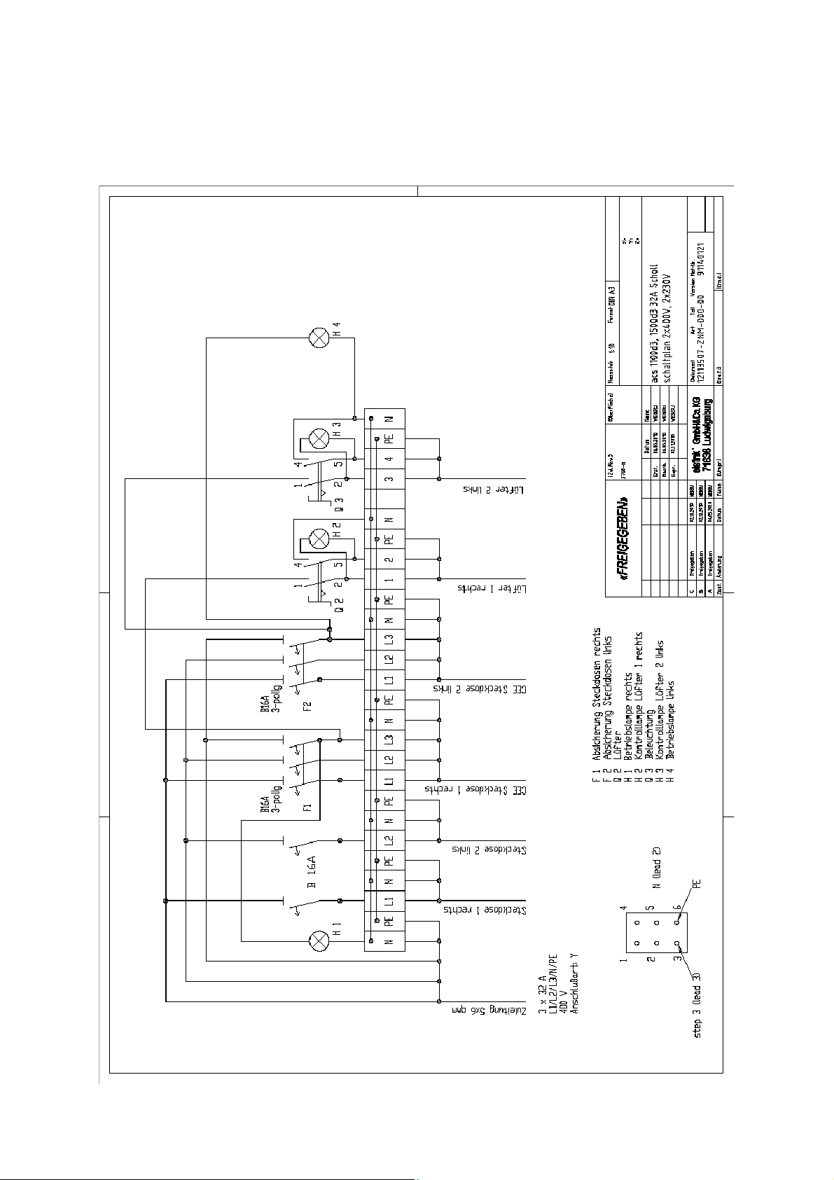
Page 18
Air Cleaning System ACS
9 varithek
®
Circuit diagram ACS 1100 d3
Table of contents
Other eisfink Air Cleaner manuals


