IntelliSAW IRM-48 User manual

IntelliSAW IRM-48 Reader
INSTALLATION MANUAL
Document:
910.00371.0001
Revision:
1.1
Date:
14 July 2016
Page 1 of 28

IntelliSAW IRM-48 Reader
Installation Manual Page 2 of 28
IRM-48 Reader 910.00371.0001
Copyright © 2016, IntelliSAW
IntelliSAW reserves the right to make technical changes or modify the contents of this document without
prior notice. IntelliSAW is not responsible for errors or possible lack of information in this document.
IntelliSAW reserves all rights in this document and in the subject matter and illustrations contained
therein. Any reproduction, disclosure to third parties or utilization of its contents, in whole or in part,
without prior written consent of IntelliSAW is forbidden.
IntelliSAW
Rosemount Measurement
100 Burtt Rd.
Andover, MA 01810
+1-978-409-1534
WARRANTY
These products are warranted to be free from functional defects in material and workmanship at time of
manufacture and to conform at that time to the specifications set forth in the relevant instruction manuals
or data sheets, for such products for a period of one year.
Reference IntelliSAW terms and conditions provided at time of purchase for complete warranty details.

IntelliSAW IRM-48 Reader
Installation Manual Page 3 of 28
IRM-48 Reader 910.00371.0001
IMPORTANT INFORMATION
This symbol identifies messages in this document related to safety.
DANGER
DANGER indicates an imminently hazardous situation, which, if not avoided, will result in death or
serious injury.
Failure to follow the instructions given will result in death or serious injury.
WARNING
WARNING indicates a potentially hazardous situation, which, if not avoided, could result in death or
serious injury.
Failure to follow the instructions given can result in death or serious injury
CAUTION
CAUTION indicates a potentially hazardous situation, which, if not avoided, may result in minor or
moderate injury.
Failure to follow these instructions can result in personal injury.
NOTICE
NOTICE alerts you to practices unrelated to personal injury, such as those that can cause property
damage.
Failure to follow these instructions can result in property damage.
IMPORTANT
IMPORTANT indicates additional information about making effective use of this product.

IntelliSAW IRM-48 Reader
Installation Manual Page 4 of 28
IRM-48 Reader 910.00371.0001
TABLE OF CONTENTS
1 Introducing the IRM-48 Reader........................................................................................... 6
1.1 Models......................................................................................................................... 6
1.2 Instructions for Use...................................................................................................... 6
2 Product Overview................................................................................................................ 7
2.1 System Inputs and Outputs.......................................................................................... 7
2.2 Labeling....................................................................................................................... 7
2.2.1 Serial ID Label...................................................................................................... 7
2.2.2 Compliance Label................................................................................................. 7
2.2.3 Product Label........................................................................................................ 8
2.3 Connectors.................................................................................................................. 8
2.3.1 USB Cable Connector........................................................................................... 9
2.3.2 Power and Modbus RTU Connector ..................................................................... 9
2.3.3 SMA (RF) Connectors........................................................................................... 9
2.3.4 Humidity Sensor Connector.................................................................................10
2.4 Power / Feedback LED...............................................................................................10
3 Installation..........................................................................................................................11
3.1 Unpacking...................................................................................................................11
3.2 Dimensions.................................................................................................................12
3.3 Din Rail Mounting .......................................................................................................12
3.3.1 Installation Location.............................................................................................13
3.3.2 Recommended Spacing.......................................................................................13
4 Wiring ................................................................................................................................14
4.1 Power and Modbus RTU Connections........................................................................15
4.1.1 Power ..................................................................................................................15
4.2 Communication Connections......................................................................................17
4.3 Humidity Sensor Connections.....................................................................................19
4.4 Air Interface Connections............................................................................................19
5 Sensor Installation & System Configuration .......................................................................20
5.1 Sensor Installation ......................................................................................................20
5.2 System Configuration..................................................................................................20
6 System Integration.............................................................................................................21
6.1 Modbus Commands....................................................................................................21
6.2 Modbus Registers.......................................................................................................22
7 Specifications.....................................................................................................................24

IntelliSAW IRM-48 Reader
Installation Manual Page 5 of 28
IRM-48 Reader 910.00371.0001
8 Product Certifications.........................................................................................................25
8.1 Compliance.................................................................................................................25
8.2 Wireless Certifications ................................................................................................26
8.2.1 Telecommunication Compliance..........................................................................26
8.2.2 Approved Antennas .............................................................................................26
8.2.3 Federal Communications Commission (FCC)......................................................26
8.2.4 Industry Canada (IC)............................................................................................27
9 Contact..............................................................................................................................28

IntelliSAW IRM-48 Reader
Installation Manual Page 6 of 28
IRM-48 Reader 910.00371.0001
1INTRODUCING THE IRM-48 READER
The IntelliSAW IRM-48 Reader is a remote monitoring unit that provides temperature, partial
discharge (PD), and humidity sensing for predictive condition-based monitoring of electrical
power critical assets such as switchgear, circuit breakers, and bus ducts. Multiple IRM Readers
can be bussed to a CAM-4 system or existing SCADA system providing immediate data display
and alarming.
1.1 MODELS
This manual covers the following models:
•IRM-48-T00: Temperature only monitoring
•IRM-48-TP0: Temperature and PD monitoring
•IRM-48-T0H: Temperature and Humidity monitoring
•IRM-48-TPH: Temperature, PD, and Humidity monitoring
1.2 INSTRUCTIONS FOR USE
The IRM-48 Reader is intended for use in the measurement of Temperature, Humidity, Ambient
Temperature, Partial Discharge and Surface Discharge of Low to Medium Voltage air insulated
Electrical Equipment. Readers connect Air Interfaces through RF cables for wireless
interrogation of SAW temperature sensors and Partial Discharge monitoring, while humidity and
ambient temperature sensors are wired to the readers. Interfacing to the IntelliSAW CAM-4 or
an existing SCADA, DCS, or historian is easily accomplished with industry standard Modbus
RTU (RS485 serial).
WARNING
The Reader is not intended for use in monitoring assets above 40KV
The reader is intended to be installed in Low Voltage compartments of switchgear or in similar
types of assets; a unit can also be installed in a weather proof environmental enclosure. The
unit is intended for use at a maximum altitude of 5km, between -40°C to +70°C and between 10
- 95% non-condensing relative humidity. The reader has been recognized for meeting UL
61010-1 safety requirements for electrical equipment. Please refer to Specifications and
Compliance for complete ratings.
WARNING
The Reader is not intended for installation in asset Medium Voltage or High Voltage
Compartments. Only sensors and antennas are intended for installation in medium
voltage Compartments.

IntelliSAW IRM-48 Reader
Installation Manual Page 7 of 28
IRM-48 Reader 910.00371.0001
2PRODUCT OVERVIEW
2.1 SYSTEM INPUTS AND OUTPUTS
The maximum system inputs and outputs are as follows:
Inputs
Outputs
12 temp sensors
Communications: Modbus RTU
4 air interfaces (PD / temp)
8 humidity sensors
Power: 24V to 60V DC (3.5W)
2.2 LABELING
The Reader has two labels on the bottom of the unit, a Serial ID label and a compliance label,
and one main product label on the top.
2.2.1 Serial ID Label
The IRM-48 Serial ID label provides a model number and serial number for the reader.
Figure 1: IRM-48 Model Number and Serial ID Label
2.2.2 Compliance Label
The compliance label provides product certification information.
Figure 2: IRM-48 Compliance Label

IntelliSAW IRM-48 Reader
Installation Manual Page 8 of 28
IRM-48 Reader 910.00371.0001
2.2.3 Product Label
The top product label provides guidance to the model type, product voltage and power ratings,
and connector interfaces.
Figure 3: Product top label
Model identification boxes will be red if the option is available in the reader.
2.3 CONNECTORS
The product has up to seven connectors (depending on model):
•(1) USB connector –used for configuration
•(1) Power and Modbus RTU (RS485) connector
•(4) SMA (RF) connectors –used for air interface connections
•(1) Ground lug –chassis Function Earth (FE)
•(1) Humidity connector –available with humidity option
Figure 4: Front and side views of IRM-485 Reader
Power &
Modbus
RTU
USB
Humidity
SMA (RF)
Model Identification
Voltage and
power ratings
Ground Lug

IntelliSAW IRM-48 Reader
Installation Manual Page 9 of 28
IRM-48 Reader 910.00371.0001
2.3.1 USB Cable Connector
Interface
Name
Description
USB
USB
USB mini used for unit configuration
2.3.2 Power and Modbus RTU Connector
Pin
Name
Description
V+
Power In +
Input power range from 24 to 60V DC.
V-
Power In -
Input power range from 24 to 60V DC.
FE
Functional Earth
This pin is used for ground and shield connectivity.
Should use separate wire from Case Ground.
D-COM
DATA Common
Common input for Modbus RTU (RS485)
DATA-
DATA Negative
Negative Input for Modbus RTU (RS485)
DATA+
DATA Positive
Positive Input for Modbus RTU (RS485)
2.3.3 SMA (RF) Connectors
Pin
Name
Description
P1
RF Port 1
Air Interface Radio Frequency Port 1
P2
RF Port 2
Air Interface Radio Frequency Port 2
P3
RF Port 3
Air Interface Radio Frequency Port 3
P4
RF Port 4
Air Interface Radio Frequency Port 4
Ground
Case Ground
Chassis ground lug connection, required for safety when air
interfaces are near energized conductors.

IntelliSAW IRM-48 Reader
Installation Manual Page 10 of 28
IRM-48 Reader 910.00371.0001
2.3.4 Humidity Sensor Connector
Pin
Name
Description
H-PWR
Humidity Power
Humidity Cable Power Input from Humidity Sensor
H-DAT
Humidity Data
Humidity Cable DATA Input from Humidity Sensor
H-CLK
Humidity Clock
Humidity Cable Clock Input from Humidity Sensor
H-COM
Humidity
Common
Humidity Cable Common Input from Humidity Sensor
2.4 POWER /FEEDBACK LED
The product has one power / feedback LED.
LED States:
•No Illumination: No Power
•Solid Green: Power, no measurements
•Green / Amber toggle: Automated measurements
•Fast flashing Amber: Rebooting
LED

IntelliSAW IRM-48 Reader
Installation Manual Page 11 of 28
IRM-48 Reader 910.00371.0001
3INSTALLATION
IMPORTANT
•The installation instructions are only for the IRM-48 Reader.
•It is assumed an Air Interface Antenna, and Sensors have been installed and configured.
WARNING
INSTALLATION AND CONFIGURATION SHOULD BE PERFORMED ONLY BY
PERSONNEL WHO ARE TECHNICALLY COMPETENT AND AUTHORIZED TO DO SO.
LOCAL REGULATIONS REGARDING ELECTRICAL INSTALLATION AND SAFETY MUST
BE OBSERVED.
Failure to follow the instructions given can result in death or serious injury
WARNING
THE USE OF THIS EQUIPMENT IN A MANNER NOT SPECIFIED IN THIS MANUAL OR BY
THE MANUFACTURER MAY IMPAIR PROTECTION OF THE USER AND EQUIPMENT.
Failure to follow the instructions given can result in death or serious injury
CAUTION
THIS EQUIPMENT IS DESIGNED FOR INSTALLATION IN AN ENCLOSURE THAT
PROVIDES ADEQUATE PROTECTION AGAINST ELECTRIC SHOCK.
Failure to follow these instructions can result in personal injury.
3.1 UNPACKING
1. Remove the product from its packing. Retain the packing for future use, to transport the
instrument to a different site or to return it to the supplier for repair/testing.
2. Examine the delivered items for damage or defects. If any are found, contact the courier
immediately.
3. In the Box:
a. Reader with a pre-installed din rail mounting clip
b. Power and Modbus RTU terminal block (6 position 5.08mm Plug)
IntelliSAW IRM-48 Reader
Installation Manual Page 12 of 28
IRM-48 Reader 910.00371.0001
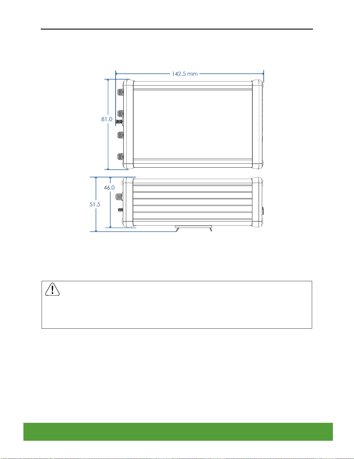
3.2 DIMENSIONS
The IRM-48 instrument has dimensions of 81 H × 142.5 W x 51.5 mm D (3.19 H × 5.61 W ×
2.03 in D).
Figure 5: IRM-48 Dimensions (in mm)
3.3 DIN RAIL MOUNTING
CAUTION
ENSURE THE INSIDE OF THE PANEL IS WITHIN THE READER’S OPERATING
TEMPERATURE AND THAT THERE IS ADEQUATE AIR FLOW TO PREVENT
OVERHEATING.
The IRM-48 Reader is mounted on standard 35 mm din rail. It can be mounted either vertically
or horizontal by changing the orientation of the mounting clip.
The din rail mounting clip is located on the back of the IRM-48 Reader and is screwed on to the
frame. The clip is normally oriented for vertical installation of the reader on to a din rail. To
change the installation mounting orientation, remove the 2 screws holding the mounting clip to
the frame of the reader. Once removed, turn the mounting clip 90 degrees in the desired
direction and screw on the mounting clip to the two additional tapped holes on the frame of the
reader.

IntelliSAW IRM-48 Reader
Installation Manual Page 13 of 28
IRM-48 Reader 910.00371.0001
Figure 6: Horizontally Installed Din Rail Mounted Reader
Figure 7: Vertically Installed Din Rail Mounted Reader
3.3.1 Installation Location
The IRM-485 Reader is intended for installation in LV compartments of switchgear, other
electrical assets, or in weather protected enclosed locations. The Reader is required to be
installed within 7m of the Air Interface, the maximum length of the Air Interface Antenna RF
cable.
3.3.2 Recommended Spacing
It is recommended to allow up to 5 cm (2 in.) for the IRM-48 Reader connectors. It is best to
have the USB connector easily accessible.

IntelliSAW IRM-48 Reader
Installation Manual Page 14 of 28
IRM-48 Reader 910.00371.0001
4WIRING
WARNING
SYSTEM WIRING SHOULD BE PERFORMED ONLY BY PERSONNEL WHO ARE
TECHNICALLY COMPETENT AND AUTHORIZED TO DO SO. LOCAL REGULATIONS
REGARDING ELECTRICAL INSTALLATION AND SAFETY MUST BE OBSERVED.
Failure to follow the instructions given can result in death or serious injury
WARNING
TO AVOID ELECTRICAL SHOCK. AC POWER WIRING MUST NOT BE CONNECTED TO
THE SOURCE UNTIL ALL WIRING CONNECTIONS PROCEDURES ARE COMPLETED.
Failure to follow the instructions given can result in death or serious injury
WARNING
CHECK THE INFORMATION LABEL ON THE CASE TO DETERMINE THE CORRECT
VOLTAGE BEFORE CONNECTING TO A LIVE SUPPLY.
Failure to follow the instructions given can result in death or serious injury
IMPORTANT
The wiring diagram below shows all possible combinations. The actual connections required
depend upon your system installation.
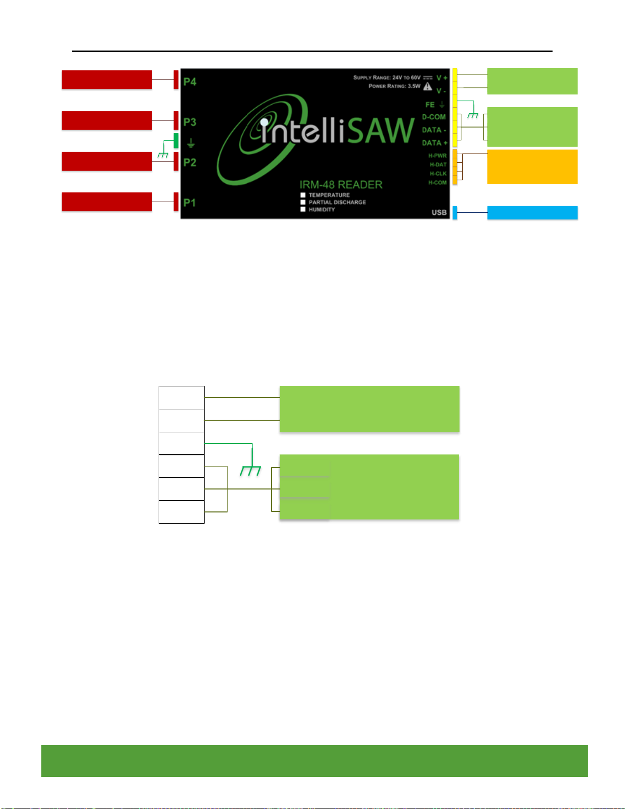
The Reader terminal connections are illustrated in the figure below. In general, all wiring
connections are made to the instrument after it is installed.
IntelliSAW IRM-48 Reader
Installation Manual Page 15 of 28
IRM-48 Reader 910.00371.0001
Power Supply
V+
V-
Modbus RTU
D-COM
DATA -
DATA +
Humidity Sensor
M12 Connector
Laptop
AIR INTERFACE ANTENNA
AIR INTERFACE ANTENNA
AIR INTERFACE ANTENNA
AIR INTERFACE ANTENNA
Figure 8: IRM-48 Connections and Common Wiring
4.1 POWER AND MODBUS RTU CONNECTIONS
The IRM-48 Reader uses a single connector for power and Modbus RTU communication. The
Connector is a 6 position Male connector. The connector accepts 16-26 AWG wire.
It is recommended that Ferrules be used for all terminating wires.
V+
V-
FE
D-COM
DATA -
DATA +
24V - 60V DC
Power Supply
V+
V-
Modbus RTU
D-COM
DATA -
DATA +
Figure 9: Power and Modbus RTU Connections
4.1.1 Power
The IRM-48 Reader operates at 48VDC nominal power, but can operate between 24 to 60V DC
with a total power consumption of 3.5 W. The following block diagram outlines the
recommended power wiring for the IRM-48 Reader with a 2-pole circuit breaker and AC/DC
power supply. Surge suppression devices can also be installed on the input line and neutral if
higher safety rating is required.
IntelliSAW IRM-48 Reader
Installation Manual Page 16 of 28
IRM-48 Reader 910.00371.0001
AC/DC
Power
Supply
N L
V+ V-
N
L
Input Power
2-pole
Circuit
Breaker
1 3
2 4
IntelliSAW
Reader
V+ V- FE
Low-voltage
Compartment FE
Figure 10: IntelliSAW Reader Recommended Power Wiring
4.1.1.1 Local versus bussed DC power
IntelliSAW recommends the use of a DC power supply in the same low-voltage compartment as
the reader. This is the simplest and most flexible option. It is possible to run a DC power bus
alongside the RS485 bus, however, this option requires careful consideration of the wire
diameter. This method also increases the likelihood of EFT or surge voltages along the DC bus.
4.1.1.2 DC power wire diameter considerations
Power connections are recommended to be a minimum 18 AWG, tin-coated, soft drawn copper
per ASTM B8, Class B stranding, 300V rated. Insulation shall be EP (ethylene propylene) or
EPCP (ethylene propylene chlorosulfonated polyethylene compound).
If bussed power is being considered, the wire gauge must be selected to prevent excessive
voltage drop between the DC power source and the reader that is electrically farthest from the
source. The larger wire diameter required could force the use of a custom cable for DC power
as the power bus wire cannot be the same gauge as the communications bus (RS485). Most
standard RS485 bus installations use wire diameters of about 0.5mm or 24 AWG; this wire size
may be too small to properly support DC power to all the readers if there are many readers a
bus.
4.1.1.3 Functional Earth wiring
Functional earth (FE) connection should always be installed between the reader’s FE terminal,
FE post, and the FE connection in the low-voltage compartment. FE at the cable connection
shunts transients at the cables, while case ground provides both RF shielding and safety
against induced voltages on air interface cables.

IntelliSAW IRM-48 Reader
Installation Manual Page 17 of 28
IRM-48 Reader 910.00371.0001
IMPORTANT
There are two INDEPENDENT connections that shall be individually wired to the
Protective Earth of the installation site such that there is an extremely low impedance
between the enclosures; this is best achieved using the shortest possible ground
cable.
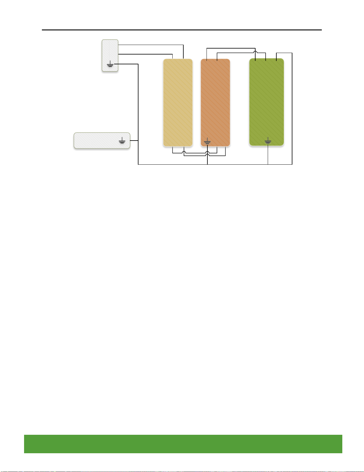
4.2 COMMUNICATION CONNECTIONS
The IntelliSAW readers are connected in a network using a standard, half-duplex RS485 bus.
This is a 3-wire bus, differential signals for data +/- and a common signal return. The common
signal is clamped to PE for safety and connects to the line driver through a high resistance to
prevent ground loops. The figure below shows the various elements of a network in a
switchgear substation.
Figure 11: RS485 Data Communication Bus Topology
4.2.1.1 Recommended Cabling
IntelliSAW recommends the use of shielded cable for the RS485 wiring, providing at least one
twisted pair, one single line, and a drain wire, although typical cable has two twisted pair. The
twisted pair provides DATA+/- signals to each reader while the single line would be for D-COM,
providing a low-impedance return for each reader.
4.2.1.2 Bus cable shielding
The drain wire associated with the RS485 bus shielding foil should be connected to the
protective earth at the source end (the end of the line segment closest to the bus master) with
the destination end left unconnected. This prevents ground loops and induced noise. Each

IntelliSAW IRM-48 Reader
Installation Manual Page 18 of 28
IRM-48 Reader 910.00371.0001
segment of the bus should be shield-terminated to the protective earth in the cabinet from which
it originates.
4.2.1.3 Bus resistive termination
The RS485 bus needs to be terminated at each end with 120 Ω resistors when long stretches of
cable are used. This ensures that the bus has the correct impedance. In general, RS485
adapters and bus masters provide the source impedance internally and should be located at
one end of the bus.
If the bus length is less than 2% of the maximum (20 meters at 9600 baud), the termination
resistor may be omitted, as long as the bus master has termination and failsafe resistors.
4.2.1.4 Bus data rate (baud rate) considerations
The RS485 bus data rate is dependent on the bus cable length and the number of readers on
the bus. In industrial environments, slower data communication rates are generally more
reliable; IntelliSAW recommends either 19200 baud or 9600 baud for the data rate.
Bus length
Bus cable length has an impact on the overall data rates which can be achieved. A
conservative rule for RS485 uses the equation: (baud rate * cable length (m)) < 10 x 106. A
9600 baud network would require a bus less of (10 x 106÷ 9600), or 1042 meters (about 3400
feet). This is perfectly adequate for most substation installations.
Number of Readers
As the number of readers increase on the RS485 bus, the baud rate must be adjusted to
accommodate the electrical characteristics of the communication protection circuits. The
following table is a guide for number of readers versus system baud rate:
Readers
Baud Rate
1
115,200
1 –8
38,400
1 –16
19,200
1 –32
9,600

IntelliSAW IRM-48 Reader
Installation Manual Page 19 of 28
IRM-48 Reader 910.00371.0001
4.3 HUMIDITY SENSOR CONNECTIONS
The Humidity Sensor Connector is a 4 position male connector. The connector accepts 16-26
AWG wire. It is recommended that Ferrules be used for all terminating wires. The IntelliSAW
Humidity sensor is shipped with a cable assembly.
H-PWR
H-DAT
H-CLK
H-COM
M12 Connector HUMIDITY
SENSOR
Figure 12: Humidity Connector
4.4 AIR INTERFACE CONNECTIONS
The IRM-48 Reader supports up to 4 Air Interface Antenna connections (P1-P4). The Air
Interface Antenna connections on the Reader are female SMA connections. The Air Interface
Antenna’s connect to the Reader through RF cables with Male SMA Connectors on each end.
RF Cables are provided by IntelliSAW when purchasing air interfaces. Only IntelliSAW provided
antennas are suitable for the desired performance and for compliance with transmitter
authorizations.
IntelliSAW IRM-48 Reader
Installation Manual Page 20 of 28
IRM-48 Reader 910.00371.0001
5SENSOR INSTALLATION &SYSTEM CONFIGURATION
5.1 SENSOR INSTALLATION
This manual does not cover specific sensor installation. Please reference the IntelliSAW
Sensor Installation Manual for more detail.
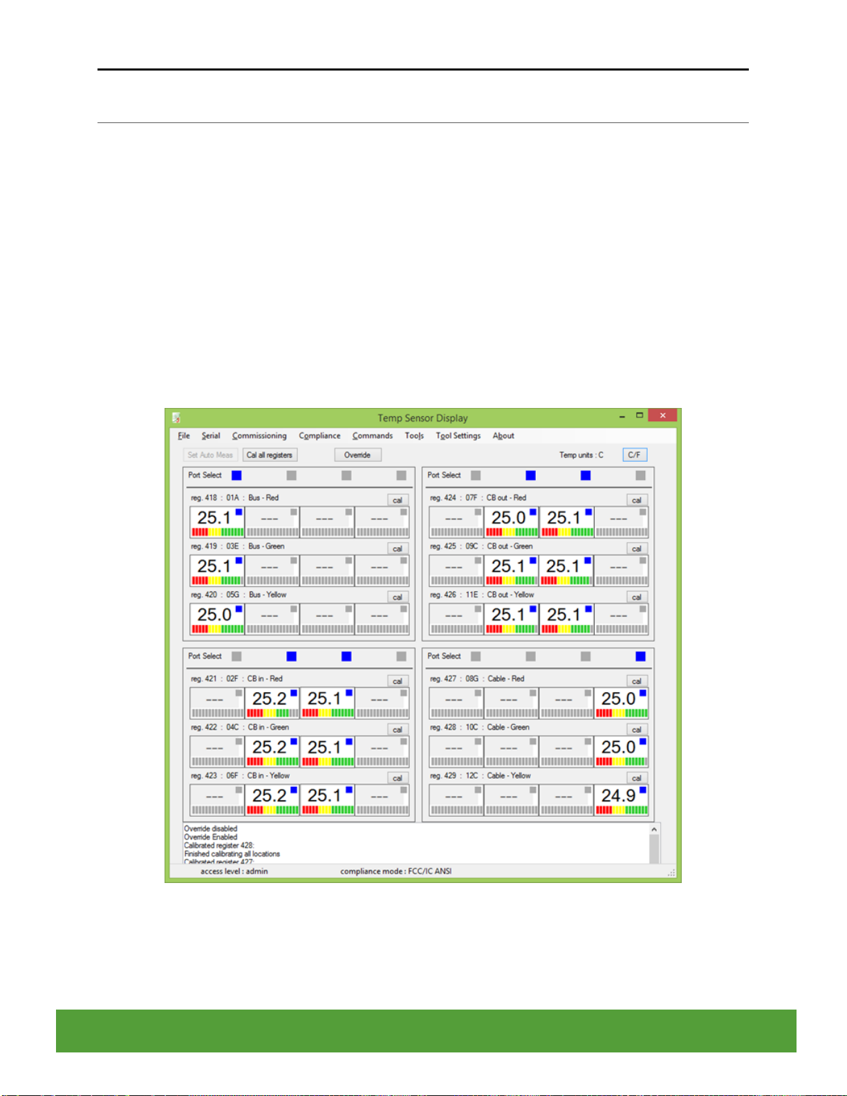
5.2 SYSTEM CONFIGURATION
The Reader requires system configuration for the associated installed temperature sensors, air
interfaces, and humidity sensors. Configuration is performed through the USB port and uses
the IntelliSAW Measurement Configuration Software. Details will not be discussed here, please
refer to the Configuration Software User Manual for detailed instructions.
Figure 13: IntelliSAW System Configuration Software
Table of contents


