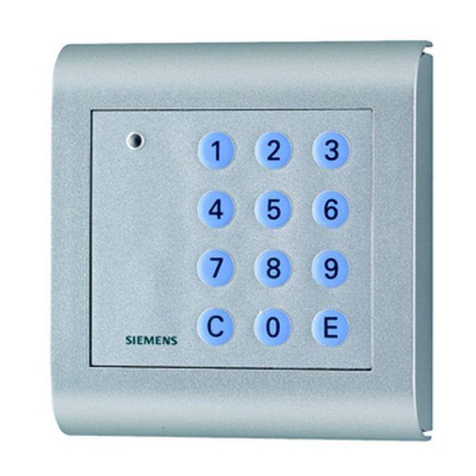
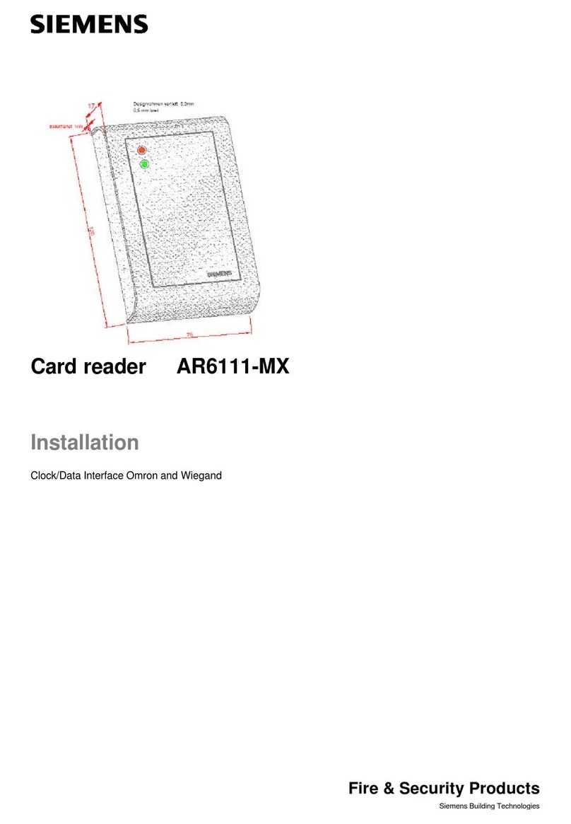
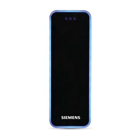
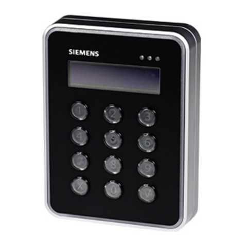
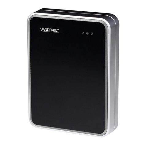
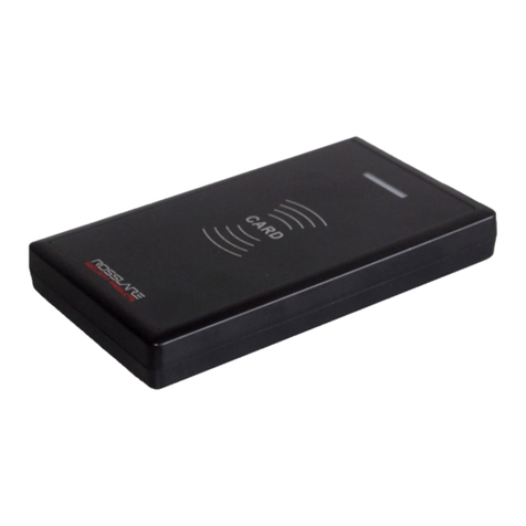
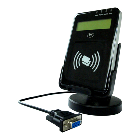
Siemens 6FL7171-8AD User manual

s
November 2003
Siemens Building Technologies
Fire & Security Products
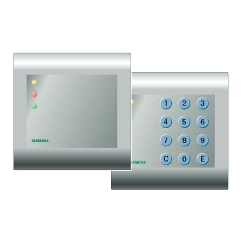
Card reader AR6331-CP / AR6332-CP
Ausweisleser AR6331-CP / AR6332-CP
Operating instructions
Betriebsanleitung
6FL7171-8AD
6FL7171-8AE
RS485, CerPass – Protocol
A
R6331-CP
A
R6332-CP

s
Page 2from 36 Operating instructions card reader AR6331-CP / AR6332-CP
Order no.: A24205-A335-H050
© 2001
Siemens Gebäudesicherheit GmbH & Co. OHG
Subject to delivery terms and technical changes
Issued by
SGS S AC
D-76187 Karlsruhe
Order no.: A24205-A335-H050
Issue: November 2003
Printed in the Federal Republic of Germany on
environmentally friendly paper produced without using
chlorine

s
Operating instructions card reader AR6331-CP / AR6332-CP Page 3from 36
Order no.: A24205-A335-H050
GB
Table of contents
1APPROVAL...................................................................................................................................4
2SAFETY REGULATIONS AND WARNINGS...............................................................................6
3GENERAL NOTES........................................................................................................................7
4INSTALLATION ............................................................................................................................8
4.1 MOUNTING .................................................................................................................................9
4.1.1 Wall-mounting ................................................................................................................9
4.1.2 Installation......................................................................................................................9
4.2 OPENING THE HOUSING............................................................................................................. 10
5SETTING UP...............................................................................................................................11
5.1 CONNECTING THE READER ........................................................................................................11
5.1.1 Power supply................................................................................................................12
5.1.2 RS485 interface ...........................................................................................................12
5.2 SETTING THE ADDRESS (BUS OPERATION)..................................................................................12
5.2.1 Setting the adress within SIPORT systems (Controller DC2000)................................ 12
5.2.2 Setting the adress within CerPass systems (Controller CC30xx)............................... 13
5.3 LED -SIGNALS.........................................................................................................................13
6APPENDIX ..................................................................................................................................14
6.1 TECHNICAL SPECIFICATIONS......................................................................................................14
6.2 DELIVERY VOLUME.................................................................................................................... 14
6.3 DIMENSIONS FOR SURFACEMOUNTING....................................................................................... 15
7NOTES ........................................................................................................................................17

s
Page 4from 36 Operating instructions card reader AR6331-CP / AR6332-CP
Order no.: A24205-A335-H050
1 Approval

s
Operating instructions card reader AR6331-CP / AR6332-CP Page 5from 36
Order no.: A24205-A335-H050
GB

s
Page 6from 36 Operating instructions card reader AR6331-CP / AR6332-CP
Order no.: A24205-A335-H050
2 Safety regulations and warnings
• The unit must only be used for the purpose intended by the manufacturer.
• When used within the EU, only in the following countries:
Germany, France, Italy, United Kingdom, Spain, Belgium, Greece, Holland, Portugal,
Austria, Sweden, Denmark, Ireland, Finland, Luxemburg.
• The operating instructions must be kept to hand and made available to every user.
• Unauthorized changes and the use of spare parts and accessories which are not sold or
recommended by the manufacturer of the unit could cause fire, electric shock or injury.
Therefore, such measures will result in a renunciation of liability and the manufacturer
will not accept any guarantee claims.
• The manufacturer's guarantee terms in the version valid at the time of the sale are
applicable to the unit. No liability will be accepted for unsuitably or incorrectly set
parameters – whether automatic or manual – or for inappropriate use of the unit.
• All repairs must be carried out by the manufacturer.
• The user is responsible for ensuring that the unit is set up and connected in accordance
with the recognized technical regulations in the country of installation and any other
guidelines valid in the relevant region.
• Before opening the unit, always switch off the power supply and take measurements to
ensure that there is no power to the unit.
• If an operating display goes out, this does not necessarily mean that the unit is
disconnected from the mains and has no power. If you are working on an open device,
remember that live components may be exposed.

s
Operating instructions card reader AR6331-CP / AR6332-CP Page 7from 36
Order no.: A24205-A335-H050
GB
3 General notes
The SIPORT ID-card readers AR6331-CP and AR6332-CP (with keypad), are new proximity
ID-Card readers in a Mullion housing, part of the new SIPORT Access reader range. The
readers read proximity CerPass ID-card (125 kHz technology). The new Mullion Access
Reader Design has been created as a simple device for wall mounting.
The identification card readers are connected via the door controller CC30xx to the CerPass
or via DC2000 to SIPORT NT Access control systems. The reader AR6331-CP and AR6332-
CP (with keypad) read the serial number of CerPass proximity ID-Cards. The card number
will be transmitted to the CerPass or SIPORT NT Access control system for processing.
The identification card readers have to be mounted on a surface as even as possible. In the
top case of the housing is the connector terminal for the connection to the door control unit
CC30xx / DC2000.
The identification card readers AR6331-CP and AR6332-CP have to be connected via a
RS485 bus-interface, 2-wire, to reader interface of an door controller CC30xx / DC2000. For
that a 4-wire, twisted pair, shielded cable is required, one pair for the 2-wire RS485 partyline
and the other pair for power supply of the reader. Max. 4 identification card readers can be
connected to one DC2000 door control unit. Up to 8 identification card readers can be
connected to one CC30xx door control unit The maximum allowed distance between the
door controller and the identification card reader is 50 m. The door management and
monitoring is controlled by the door control unit.
The data transmission of the system from the usercards to the identification card readers is
based on a electro-magnetic field, which is created by the aerial of the identification card
reader. If the ID-card is approximated to the electromagnetic field of the reader-aerial , it is
supplied with energy and sends its personalised data. The data is received by the reader-
antenna.
The reading range of the identification card readers AR6331-CP and AR6332-CP, depending
on the kind of the arrangement and material the reader is mounted on, is up to 70 mm. The
kind of the transponder ID-card has also an important influence to the reading distance; e.g.
ID-card, keyfob, etc.. Electrical leading materials, like metal and metalized glass surfaces,
can influence the spatial spreading of the electro-magnetic fieldlines. The lateral distance
between the identification card reader and metallic objects must be at least 30 cm.
Otherwise, the reading range is reduced.
The spatial distance to neighboured identification card readers should not be less than 50
cm, to prevent mutual influence of the electro-magnetic fields and data transmission
problems. Attention should also be paid to install the identification card readers not near to
computer-terminals, TV sets and so on, because of the negative influence to the range area.
If the identification card reader is mounted on metal walls or metalized glass surfaces, the
reading range can be reduced.
The whole electronic together with the transmit / receive-antenna is housed in a shockproof
plastic case.
Installation according to the type of protection IP65 (only with seal; alternatively, the hole can
be sealed with silicone before the screw is inserted (reader housing must be closed)). Avoid
installing the reader in places where it is subject to direct sunlight.
The reader has 3 LED’s in the colours yellow, green and red and an internal buzzer.
For the keypad operation with the reader AR6332-CP please note: Connecting the
reader to a door control unit CC30xx the PIN can be entered either before or after the
card (card follows PIN, PIN follows card). Connecting the reader to a DC2000 door
control unit the PIN has to be entered before the card (card follows PIN). Keypad
operates only with DC2000 Firmware - version above 2.0!

s
Page 8from 36 Operating instructions card reader AR6331-CP / AR6332-CP
Order no.: A24205-A335-H050
4 Installation
The reader is designed to be surface mounted.
NOTES:
• If the reader should be mounted directlyonto condictive materials, such as metal
surfaces, metal frames (reinforcement) or metal-plated surfaces, this will reduce,
more or less, the readers read range.
• The distance between readers of the same design should not be less than 30 cm.
• Before final installation, the planned installation site should be checked for
suitability.
• You can tell the direction of the bottom section of the housing from the inscription
"TOP
!
". The arrow must point upwards!
TOP
!
Figure 1: Installation direction

s
Operating instructions card reader AR6331-CP / AR6332-CP Page 9from 36
Order no.: A24205-A335-H050
GB
4.1 Mounting
4.1.1 Wall-mounting
The unit should be installed on as even a surface as possible.
• Create openings for the lead in the bottom section of the housing and pull the lead
through.
• Screw the bottom of the housing onto the selected position on the wall.
• End of lead should be fixed at the bottom section (see figure below).
Figure 2: Back view of the bottom section of the housing with the terminal board slotted in
4.1.2 Installation
• The electronic board (pcb) with terminal connectors is build into the top section of the
housing.
• Connect the cable to the terminal strip (pcb) in the top section of the housing.
See chapter „5.1 Connecting the reader”
• First, insert top section of housing on top part of mounted bottom section of the housing.
• Then, push both parts of the reader housing together. In doing so, keep attention on the
wires.
• Screw in the safety screw on the underneath of the bottom section of the housing.
Note
The maximum torque of the safety screw is 1,5 Nm.

s
Page 10 from 36 Operating instructions card reader AR6331-CP / AR6332-CP
Order no.: A24205-A335-H050
4.2 Opening the housing
Proceed as follows when opening the housing.
• Undo the safety screw (1)
• Lift of the lwer end of the top section of the housing (2). Keep attention, to lift of carefull
and watch the sabotage contact lever. After lifting of, please move the top section
upwards (2) till the top section feels free to remove.
• Remove the top section of the housing from the bottom section.
Figure 3: Opening the housing

s
Operating instructions card reader AR6331-CP / AR6332-CP Page 11 from 36
Order no.: A24205-A335-H050
GB
5 Setting up
5.1 Connecting the reader
The reader is connected using the terminal strip (see: “Figure 4: Electronic board”) of the
reader mounted into the top section of the housing.
Connector for keypad type AR6332-CP
Switches for adress
- + A B
Figure 4: Electronic board, connectors
Terminal Function
Strip Description AR633x-CP card reader
- Power supply 0 volt DC
+ Power supply +12 volt DC
A RS485 - A
B RS485 - B
Connector positions from left to right (top view)
Table 1: Terminal allocation on the terminal board

s
Page 12 from 36 Operating instructions card reader AR6331-CP / AR6332-CP
Order no.: A24205-A335-H050
5.1.1 Power supply
The power is supplied through terminals [+] and [-]. The unit can run off 12 Volt DC. For DC
voltage supply the polarity is fix!.
NOTE:
The length of cable between the power pack and the reader should be kept as
short as possible. The lead should not be laid directly parallel to other energy
supply and low voltage cables.
5.1.2 RS485 interface
With RS485 data buses, it can be necessary to use terminating resistors. For each
installation, checks should be made as to whether it is necessary to use terminating
resistors. Generally, a terminating resistor is only required at the end of the bus, i.e. on the
last unit. In order to do this, use jumper J1 on reader electronic board.
To operate the bus, you need a central computer with a terminating resistor and active
termination (see Figure 5: Operating a bus with an RS485 interface)
Controller
Without terminating resistor
AB
AR 6331-CP AR 6331-CP AR 6331-CP
100 Ohm
(with active terminationung)
With terminating resistor
A
B
Jumper J1
Figure 5: Operating a bus with an RS485 interface
5.2 Setting the address (bus operation)
5.2.1 Setting the adress within SIPORT systems (Controller DC2000)
Bus operation with up to 4 readers connected to controller DC2000. All card readers are
issued an individual address as shown in Table 2.
DIP 4 DIP 3 DIP 2 DIP 1 Bus adress
off off off off 0
off off off on 1
off off on off 2
off off on on 3
Table 2: Bus addresses within SIPORT

s
Operating instructions card reader AR6331-CP / AR6332-CP Page 13 from 36
Order no.: A24205-A335-H050
GB
5.2.2 Setting the adress within CerPass systems (Controller CC30xx)
Bus operation with up to 8 readers connected to controller CC30xx. All card readers are
issued an individual address as shown in Table 3.
DIP 4 DIP 3 DIP 2 DIP 1 Bus adress
off off off off 1
off off off on 2
off off on off 3
off off on on 4
off on off off 5
off on off on 6
off on on off 7
off on on on 8
on off off off 9
on off off on 10
on off on off 11
on off on on 12
on on off off 13
on on off on 14
on on on off 15
on on on on 16
Table 3: Bus adresses within CerPass
5.3 LED - signals
The following functions are signalised by the LED’s.
Yellow operation (standby)
blinking yellow no connection to the door control unit
green authorised
Red not authorised
steadylight red Card reader blocked, no cards accepted

s
Page 14 from 36 Operating instructions card reader AR6331-CP / AR6332-CP
Order no.: A24205-A335-H050
6 Appendix
6.1 Technical specifications
• Housing PC/ABS plastic
Fire class HB acc. UL94 (IEC707)
Temperature stability: up to 110°C
• Color
Top section of housing:
Bottom section of housing:
similar to RAL 9006 (white aluminum)
• Weight approx. 200 g
• Degree of protection IP 40, IP65 with seal
• Power supply 12 V DC SELV (Safety Electrical Voltage)
• Power consumption max. 1 W
• Temperature range -10to +55 °C
• Relative air humidity 95% (no dew formation)
• Antenna integrated
• Data transfer using transponder 125 kHz / AM / half-duplex
• for transponder - with CerPass – coding (e.g. DZ3022)
• Transducer • 3 x LEDs, yellow, red, green
• 1 x buzzer
• Interfaces:
• RS485 2-wire (CerPass – reader protocol)
DC2000 - max. 4 readers
CC30xx – max. 8 readers
• 9600 Baud, 8 data bits, 1 stop bit, no parity
• Address setting for interface • DIP switches
• EEPROM
Options:
10,000 write cycles
Keypad (0 – 9, C, E)
6.2 Delivery volume
1 x housing; upper part with reader electronic, frontfoil and connection terminals, seal
1 x housing; lower part
1 x accessory bag
1 x Operating instructions
1 x repair form

s
Operating instructions card reader AR6331-CP / AR6332-CP Page 15 from 36
Order no.: A24205-A335-H050
GB
6.3 Dimensions for surface mounting

s
Page 16 from 36 Operating instructions card reader AR6331-CP / AR6332-CP
Order no.: A24205-A335-H050

s
Operating instructions card reader AR6331-CP / AR6332-CP Page 17 from 36
Order no.: A24205-A335-H050
GB
7 Notes

s
Page 18 from 36 Operating instructions card reader AR6331-CP / AR6332-CP
Order no.: A24205-A335-H050
Copyright 2003 by Siemens Gebäudesicherheit
Issue: November 2003 - This manual supercedes and renders invalid all earlier versions. The information in this
manual can be changed without prior notice.
This document and its contents may not be passed on, reproduced, used or communicated in any way
without explicit consent. Any contravention of this will result in a right to claim for damages. All rights
reserved in the event that a patent is granted or the product is GM registered.
The information in this manual has been put together to the best of the authors' knowledge and conscience.
Siemens Gebäudesicherheit accepts no liability for the accuracy or completeness of the information in this
manual. In particular, Siemens Gebäudesicherheit cannot be held liable for consequential damages caused as a
result of incorrect or incomplete information. As it is impossible to avoid mistakes despite all our efforts, we are
always grateful if these are pointed out.
The installation recommendations contained in this manual assume the most favorable framework conditions.
Siemens Gebäudesicherheit cannot guarantee that the system will function perfectly under other conditions.
Siemens Gebäudesicherheit cannot guarantee that the information contained in this document is not protected by
external property rights. By publishing this document, Siemens Gebäudesicherheit is not granting licenses to its
own or external patents or other property rights.

s
November 2003
Siemens Building Technologies
Fire & Security Products
Ausweisleser AR6331-CP / AR6332-CP
Betriebsanleitung
6FL7171-8AD
6FL7171-8AE
RS485, CerPass – Protocol
A
R6331-CP
A
R6332-CP

s
Seite 20 von 36 Bedienungsanleitung Ausweisleser AR6331-CP / AR6332-CP
Bestell Nr.: A24205-A335-H050
© 2001
Siemens Gebäudesicherheit GmbH & Co. OHG
Liefermöglichkeiten und technische Änderungen vorbehalten
Herausgegeben von
SGS S AC
D-76187 Karlsruhe
Bestell-Nr: A24205-A335-H050
Ausgabe: November 2003
Gedruckt in der Bundesrepublik Deutschland
auf umweltfreundlich chlorfrei hergestelltem Papier
This manual suits for next models
1
Table of contents
Languages:
Other Siemens Card Reader manuals

Siemens
Siemens AR4 S-MF Series Installation instructions manual

Siemens
Siemens AR10S-MF Installation instructions manual

Siemens
Siemens SIMATIC RF300 User guide

Siemens
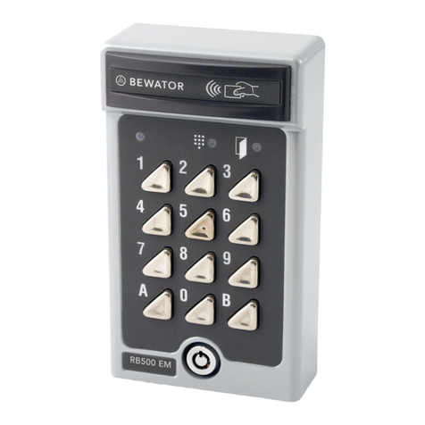
Siemens RB500 User manual

Siemens
Siemens SIMATIC RF310M User manual

Siemens
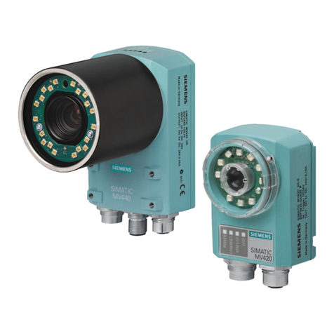
Siemens SIMATIC MV440 User manual

Siemens
Siemens PM500-Cotag User manual

Siemens
Siemens SIMATIC RF650M User manual

Siemens
Siemens AR6181-MS User manual

Siemens
Siemens PR500-Cotag User manual