IntelliSAW CAM-5 User manual

User Manual
910.00382.0001
May 2018
IntelliSAW CAM™-5
Condition Asset Monitoring

User Manual
910.00382.0001 May 2018
2

User Manual
May 2018 910.00382.0001
3
Contents
Contents........................................................................................................................................................3
Important Information....................................................................................................................................6
Section 1 Introduction................................................................................................................................7
1.1 Models...........................................................................................................................................7
1.2 Instructions for Use .......................................................................................................................8
1.3 System Inputs and Outputs...........................................................................................................8
1.4 Labeling.........................................................................................................................................9
1.4.1 Back Label.................................................................................................................................9
1.4.2 Serial Number, Safety and Compliance Label........................................................................10
Section 2 Installation...............................................................................................................................11
2.1 Unpacking ...................................................................................................................................12
2.2 Dimensions..................................................................................................................................12
2.3 Connectors..................................................................................................................................13
2.3.1 Power Connector.....................................................................................................................15
2.3.2 Chassis Ground Connector –Protective Earth.......................................................................16
2.3.3 Ethernet Connector.................................................................................................................16
2.3.4USB Mini-B Cable Connector..................................................................................................16
2.3.5 USB Standard-A Connector....................................................................................................16
2.3.6 SD Micro Connector................................................................................................................17
2.3.7 SCADA Connectors.................................................................................................................17
2.3.8 Devices Connector..................................................................................................................18
2.3.9 SMA (RF) Connectors.............................................................................................................18
2.3.10 Humidity Sensor Connector ................................................................................................18
2.3.11 Relay Alarm Connector.......................................................................................................19
2.4 Panel Mounting ...........................................................................................................................20
2.4.1 Installation Location ................................................................................................................20
2.4.2 Panel Cutout............................................................................................................................20
2.4.3 Mounting Bracket Installation..................................................................................................20
Section 3 Wiring ......................................................................................................................................22
3.1 Power Connection.......................................................................................................................24
3.1.1 Input Power Details.................................................................................................................24
3.1.2 Protective Earth (PE) wiring....................................................................................................26
3.2 RS485 Communication (Device and SCADA) ............................................................................26
3.2.1 CAM-5 Connection to Readers...............................................................................................27
3.2.2 CAM-5 Connections to External SCADA ................................................................................28

User Manual
910.00382.0001 May 2018
4
3.2.3 RS485 Cabling........................................................................................................................28
3.2.4 Bus Termination......................................................................................................................29
3.2.5 Bus data rate (baud rate) considerations................................................................................29
3.3 Humidity Sensor Connections.....................................................................................................29
3.4 Air Interface Connections............................................................................................................30
3.5 Alarm Wiring................................................................................................................................31
3.6 Example Wiring Diagram ............................................................................................................33
Section 4 HMI Overview..........................................................................................................................34
4.1 Home Screen ..............................................................................................................................34
4.1.1 Home Screen Segments.........................................................................................................34
4.1.2 HMI Warning & Alarm Indications ...........................................................................................36
4.1.3 Unit Details & Measurement Selection....................................................................................38
4.1.4 Versions ..................................................................................................................................38
4.1.5 Network ...................................................................................................................................38
4.1.6 Capture & Log Files ................................................................................................................39
4.1.7 Reboot.....................................................................................................................................39
4.1.8 Date.........................................................................................................................................39
4.2 Device Specific Detail Screens ...................................................................................................40
4.2.1 Device Detail Screen Overview...............................................................................................40
4.2.2 Temperature Measurements...................................................................................................42
4.2.3 Humidity and Ambient Temperature .......................................................................................44
4.2.4 Partial Discharge.....................................................................................................................46
Section 5 HMI Configuration ...................................................................................................................50
Section 6 Measurement Configuration & Sensor Installation..................................................................51
6.1 Measurement Configuration........................................................................................................51
6.2 Sensor Installation.......................................................................................................................52
Section 7 SCADA System Integration.....................................................................................................53
7.1 Modbus RTU or TCP...................................................................................................................53
7.1.1 MODBUS COMMANDS..........................................................................................................53
7.1.2 MODBUS REGISTERS...........................................................................................................54
7.2 DNP3...........................................................................................................................................57
7.2.1 DNP3 flags..............................................................................................................................58
7.2.2 DNP3 Settings.........................................................................................................................58
7.2.3 DNP3 TLS and Secure Authentication....................................................................................58
7.3 IEC 61850 ...................................................................................................................................58
7.3.1 Logical Nodes List...................................................................................................................58
7.3.2 Mapping of Modbus to IEC61850............................................................................................59
7.3.3 Mapping of Digital Output to IEC61850 ..................................................................................61

User Manual
May 2018 910.00382.0001
5
Section 8 Specifications..........................................................................................................................62
Section 9 Product Certifications..............................................................................................................66
9.1 Compliance Testing ....................................................................................................................66
9.2 Wireless Certifications.................................................................................................................67
9.2.1 Telecommunication Compliance.............................................................................................67
9.2.2 Approved Antennas.................................................................................................................67
9.2.3 Federal Communications Commission (FCC) ........................................................................68
9.2.4 Industry Canada (IC)...............................................................................................................68
Contact........................................................................................................................................................70

User Manual
910.00382.0001 May 2018
6
Important Information
This symbol identifies messages in this document related to safety.
DANGER
DANGER indicates an imminently hazardous situation, which, if not avoided, will result in death or
serious injury.
Failure to follow the instructions given will result in death or serious injury.
WARNING
WARNING indicates a potentially hazardous situation, which, if not avoided, could result in death or
serious injury.
Failure to follow the instructions given can result in death or serious injury
CAUTION
CAUTION indicates a potentially hazardous situation, which, if not avoided, may result in minor or
moderate injury.
Failure to follow these instructions can result in personal injury.
NOTICE
NOTICE alerts you to practices unrelated to personal injury, such as those that can cause property
damage.
Failure to follow these instructions can result in property damage.
IMPORTANT
IMPORTANT indicates additional information about making effective use of this product.

User Manual
May 2018 910.00382.0001
7
Section 1 Introduction
The IntelliSAW CAM™-5 provides a local human machine interface (HMI) with remote monitoring
capabilities (temperature, partial discharge, and humidity / ambient temperature), data trending and
alarming, data aggregation, and multiple communication interfaces such as Modbus TCP, DNP-3, and
IEC61850 to integrate into existing SCADA / DCS systems.
The CAM-5 can be a stand-alone system ideal for predictive condition-based monitoring of electrical
power critical assets such as switchgear, generator circuit breakers, and bus ducts.
This manual covers CAM-5 functionality, configuration, safety, and installation.
1.1Models
The following tables outline available CAM-5 models.
Model Number
Description
CAM5B-TPH-AMEU
CAM5 Base:
- Monitoring: Temperature, PD, Ambient Temp &Humidity
- Alarm outputs –6 ch. (NO/NC)
- Multiunit Device Interface (RS485)
- Communication interface: Ethernet
- Standard communication: Modbus TCP
- Universal Input Power (100 to 250 VAC; 120 to 250VDC1)
CAM5B-T00-AMEU
CAM5 Base:
- Monitoring: Temperature
- Alarm outputs –6 ch. (NO/NC)
- Multiunit Device Interface (RS485)
- Communication interface: Ethernet
- Standard communication: Modbus TCP
- Universal Input Power (100 to 250 VAC; 120 to 250VDC1)
CAM5B-000-AMEU
CAM5 Base:
- No Monitoring
- Alarm outputs –6 ch. (NO/NC)
- Multiunit Device Interface (RS485)
- Communication interface: Ethernet
- Standard communication: Modbus TCP
- Universal Input Power (100 to 250 VAC; 120 to 250VDC1)
CAM5B-TPH-AMFU
CAM5 Base:
- Monitoring: Temperature, PD, Ambient Temp & Humidity
- Alarm outputs –6 ch. (NO/NC)
- Multiunit Device Interface (RS485)
- Communication Interface: Fiber Optic (100 base FX)
- Standard communication: Modbus
- Universal Input Power (100 to 250 VAC; 120 to 250VDC1)
CAM5B-T0H-AMEU
CAM5 Base:
- Monitoring: Temperature, Ambient Temp &Humidity
- Alarm outputs –6 ch. (NO/NC)
- Multiunit Device Interface (RS485)
- Communication interface: Ethernet
- Standard communication: Modbus TCP
- Universal Input Power (100 to 250 VAC; 120 to 250VDC1)
1
DC operation has not been evaluated for FCC Part 15 or c/UL/IEC 61010-1.

User Manual
910.00382.0001 May 2018
8
1.2Instructions for Use
The CAM-5 is intended to be installed in the Low Voltage compartment of switchgear or in similar types of
assets. The CAM-5 is intended for use at a maximum altitude of 5km, between -25°C to +70°C (+55°C at
250VAC input) and between 10 - 95% non-condensing relative humidity.
WARNING
THE CAM-5 IS INTENDED ONLY FOR INSTALLATION IN LOW VOLTAGE CONTROL
COMPARTMENTS.
ONLY SENSORS AND AIR INTERFACES ARE INTENDED FOR INSTALLATION IN MEDIUM / HIGH
VOLTAGE COMPARTMENTS.
ONLY WIRELESS SENSORS ARE INTENDED FOR CONTACT WITH ENERGIZED CONDUCTORS
ABOVE 300VRMS.
Failure to follow the instructions given can result in death or serious injury
1.3System Inputs and Outputs
The maximum system inputs and outputs are as follows:
Inputs
Outputs
12 SAW wireless temp sensors
Communications:
Modbus RTU (SCADA)2
Modbus TCP
DNP3
IEC61850
Email alarms3
SMS alarms4
4 air interfaces (TMP or TPD)
8 humidity sensors (series connected)
Modbus RTU (Devices)
Power: 100 to 250V AC 50/60 Hz (20W)
120 to 250V DC1
Alarms: 6 Form C (NO / NC) relays with a
shared common (COM)
2
MODBUS RTU output requires a non-standard model with RS485 communications card.
3
Email alarms require connectivity to a user-supplied SMTP server and valid email account for sending data.
4
SMS is only supported via a compatible cellular gateway device with a user-supplied SIM card and plan.

User Manual
May 2018 910.00382.0001
9
1.4Labeling
The CAM-5 has two identification labels. The back label provides model number and device specific
connections. The safety and compliance label on the top provides product serial number, certification
information and installation ratings.
1.4.1Back Label
The back label is unique per model number as the connectors will change. Each label identifies the unit
model number.
Figure 1: Example CAM-5 back label
User Manual
910.00382.0001 May 2018
10
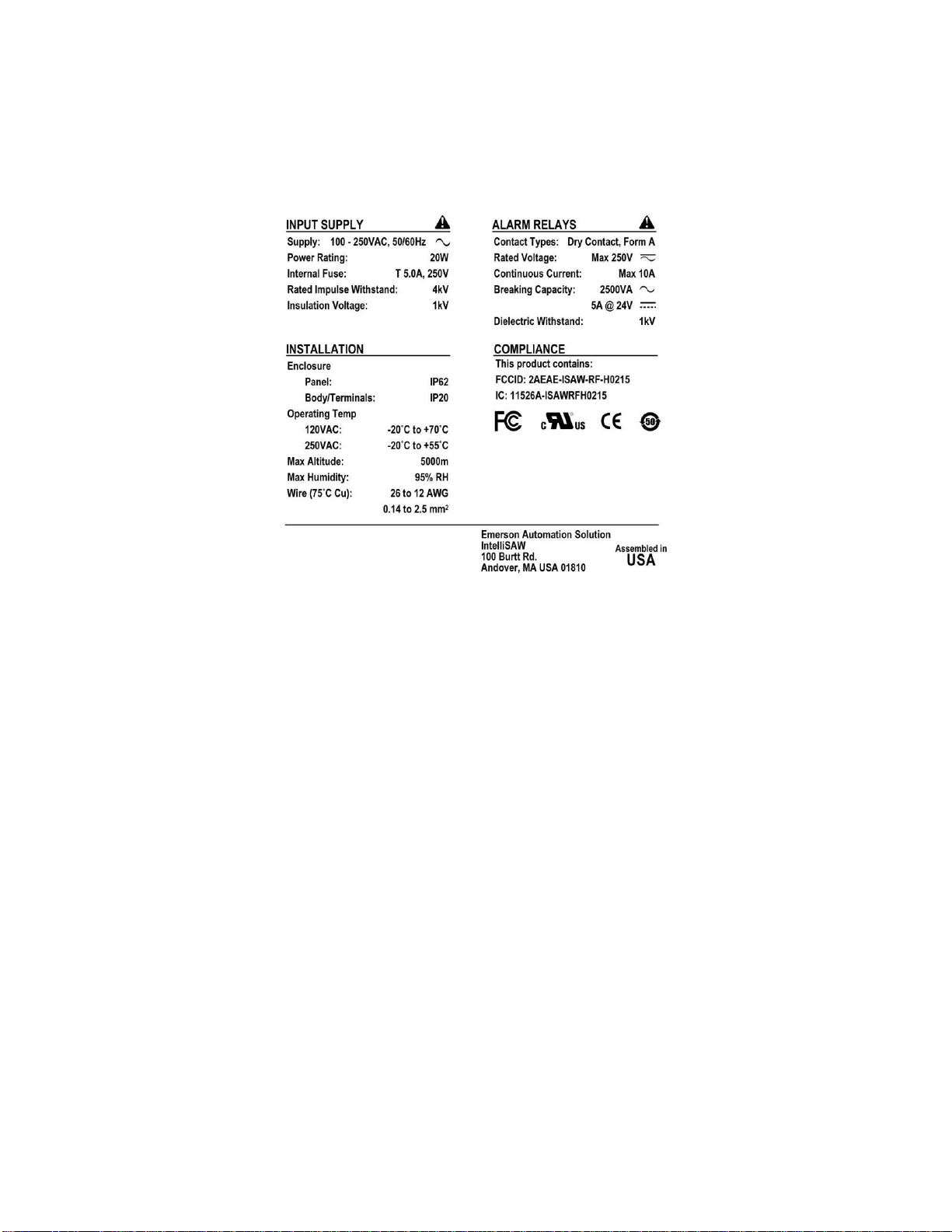
1.4.2Serial Number, Safety and Compliance Label
The safety and compliance label located at the top of the unit provides the product serial number,
manufacturer information, compliance information, along with input supply, installation, and alarm relay
ratings.
Figure 2: CAM-5 Safety and Compliance Label

User Manual
May 2018 910.00382.0001
11
Section 2 Installation
WARNING
INSTALLATION AND CONFIGURATION SHOULD BE PERFORMED ONLY BY PERSONNEL WHO
ARE TECHNICALLY COMPETENT AND AUTHORIZED TO DO SO. LOCAL REGULATIONS
REGARDING ELECTRICAL INSTALLATION AND SAFETY MUST BE OBSERVED.
Failure to follow the instructions given can result in death or serious injury
WARNING
THE USE OF THIS EQUIPMENT IN A MANNER NOT SPECIFIED IN THIS MANUAL OR BY THE
MANUFACTURER MAY IMPAIR PROTECTION OF THE USER AND EQUIPMENT.
Failure to follow the instructions given can result in death or serious injury
CAUTION
THIS EQUIPMENT IS DESIGNED FOR INSTALLATION IN AN ENCLOSURE THAT PROVIDES
ADEQUATE PROTECTION AGAINST ELECTRIC SHOCK.
Failure to follow these instructions can result in personal injury.
NOTICE
The product is recognized as a component under c/UL/IEC 61010-1 and c/UL/IEC 61010-3 and has
been evaluated under IEC61000-6-5 in type 4 interface applications. The 61010-1 and -3 component
recognitions assume the following, which were not specifically evaluated for the product as a
component:
•Spacing of all wired components from energized conductors meets the greater of double
insulation under c/UL/IEC61010 or the BIL requirements of the host equipment.
•Wired sensors are installed and cabled in accordance with instructions.
Note that introduction of a recognized component into a previously recognized system requires
evaluation of the modified system for c/UL recognition.
Failure to follow these instructions can result in operation outside the c/UL recognition of the
product and/or host equipment.

User Manual
910.00382.0001 May 2018
12
2.1Unpacking
1. Remove the product from its packing. Retain the packing for future use, to transport the
instrument to a different site or to return it to the supplier for repair/testing.
2. Examine the delivered items for damage or defects. If any are found, contact the courier
immediately.
3. In the Box:
a. CAM-5 Unit
b. Power terminal block (2 position 7.62mm Plug)
c. Devices terminal block (6 position 3.5mm Plug) if option exists
d. SCADA terminal block (6 position 3.5mm Plug) if option exists
e. Alarm terminal block (5 position plug) if option exists
f. 16GB USB Flash Drive
g. (4) Mounting Clips
2.2Dimensions
The CAM-5 HMI instrument has front screen dimensions of 153.4 mm W x 110.2 H with a face depth of
3.14 mm. The Body dimensions of the CAM-5 are 143.6 W x 100.25 H x 101.6 mm D.
Figure 3: CAM-5 Dimensions (in mm)

User Manual
May 2018 910.00382.0001
13
2.3Connectors
The product has up to fourteen connectors (depending on model):
Standard Connectors:
•(1) Input Power Connector
•(1) USB connector (Mini-B) –used for measurement configuration
•(1) USB connector (Standard-A) –used for data logging
•(1) SD Micro card –for factory and future use.
•(1) Ethernet Connector (system)
•(1) Ground lug –chassis ground
Optional Connectors:
•(4) SMA (RF) connectors –used for air interface connections
•(1) Alarms Connector
•(1) Devices (RS485) Connector –Reader Input through Modbus RTU
•(1) Humidity connector
•(1) SCADA Connector
oRS485 - integration through Modbus RTU
oFiber Connector
oEthernet Connector
Figure 4: CAM-5 Back View
DEVICES
Humidity
Ground Lug
Power
SMA (RF)
Ports
SCADA
Alarms
USB-Standard-A
USB-Mini-B
Ethernet (system)

User Manual
910.00382.0001 May 2018
14
Figure 5: CAM-5: Left Side View
IMPORTANT
External radio frequency energy sources located close to the RF ports can reduce the sensitivity of
partial discharge measurements.
IMPORTANT
The status LED of the RF card is visible through the ventilation slots.
LED States:
•No Illumination: No Power to RF measurement card
•Solid Green: Power, no measurements
•Green / Amber toggle: Automated measurements enabled
•Fast flashing Amber: Rebooting
SD Card
Mounting Clip
Slots
Ventilation
RF Card LED
Mounting Clip
Slots

User Manual
May 2018 910.00382.0001
15
Figure 6: CAM-5: Right Side View
WARNING
INSERTION OF WIRES OR FINE TOOLS INTO THE VENTILATION SLOTS COULD RESULT IN
HAZARDOUS CONDITIONS.
Failure to follow the instructions given can result in death or serious injury
2.3.1Power Connector
Pin
Name
Description
Line / (+)
Line 1, DC+
Input power range:
100 to 250V AC and 120 to 250V DC1.
2-Phase AC uses (N / -) as Line 2
Neutral / (-)
Neutral, Line 2, DC-
Line and Neutral are symmetric in the CAM™-5 and DC power may be applied at either polarity.
Line and Neutral have differential mode filtering and clamping to PE stud and have common
mode filtering and isolation to the remainder of the unit.
Mounting Clip
Slots
Ventilation

User Manual
910.00382.0001 May 2018
16
2.3.2Chassis Ground Connector –Protective Earth
Interface
Name
Description
Lug
Protective Earth
Chassis ground / protective earth lug connection, required for
safety when air interfaces are near energized conductors.
2.3.3Ethernet Connector
Interface
Name
Description
RJ45
Ethernet (ETH-1)
Used for configuration and Ethernet communication (10/100
BASE-T)
2.3.4USB Mini-B Cable Connector
Interface
Name
Description
Mini-B
CNFG
USB Mini-B used for unit configuration
2.3.5USB Standard-A Connector
Interface
Name
Description
Host-A
USB
USB Host-A used for image capture and data storage. Also used
for software and configuration file uploads.
WARNING
THE CAM-5 IS DESIGNED TO ISOLATE THE USB PORTS FROM HAZARDOUS CONDITIONS
INTRODUCED FROM INCOMING CABLES AND THE ENERGIZED EQUIPMENT.
IT IS NOT ADVISED TO USE THESE PORTS OTHER THAN AS FOLLOWS.
•USB-MINI-B: SHORT TERM USE FOR CONFIGURATION AND VERIFICATION. NOT FOR
LONG TERM DATA COLLECTION.
•USB-HOST-A: LONG TERM DATA LOGGING WITH INFREQUENT REMOVAL AND
REPLACEMENT FOR DATA COLLECTION.
Failure to follow the instructions given can result in death or serious injury

User Manual
May 2018 910.00382.0001
17
2.3.6SD Micro Connector
Interface
Name
Description
SD Micro
SD Micro
SD card for factory use only
2.3.7SCADA Connectors
SCADA interface is determined by model number.
2.3.7.1Modbus RTU Connector
Pin
Name
Description
DATA-
DATA Negative
Negative Input for Modbus RTU (RS485)
DATA-
DATA Negative
Redundant Negative Input for Modbus RTU (RS485)
DATA+
DATA Positive
Positive Input for Modbus RTU (RS485)
DATA+
DATA Positive
Redundant Positive Input for Modbus RTU (RS485)
D-COM
DATA Common
Common input for Modbus RTU (RS485)
D-COM
DATA Common
Redundant Common input for Modbus RTU (RS485)
2.3.7.2Ethernet Connector
Interface
Name
Description
RJ45
Ethernet (ETH-2)
Used for SCADA communication (10/100 BASE-T)
2.3.7.3Fiber Connector
Interface
Name
Description
LC
FIBER (100Base-FX)
Used for SCADA communication

User Manual
910.00382.0001 May 2018
18
2.3.8Devices Connector
Redundant terminals are provided for ease of use, for daisy chaining RS-485 where the CAM-5 is not the
last device on the network. Where it is the last device, a ½ Watt 120 Ohm resistor should be placed
between one Data+ and Data–.
Pin
Name
Description
DATA-
DATA Negative
Negative Input for Modbus RTU (RS485)
DATA-
DATA Negative
Redundant Negative Input for Modbus RTU (RS485)
DATA+
DATA Positive
Positive Input for Modbus RTU (RS485)
DATA+
DATA Positive
Redundant Positive Input for Modbus RTU (RS485)
D-COM
DATA Common
Common input for Modbus RTU (RS485)
D-COM
DATA Common
Redundant Common input for Modbus RTU (RS485)
2.3.9SMA (RF) Connectors
Pin
Name
Description
P1
RF Port 1
Air Interface Radio Frequency Port 1
P2
RF Port 2
Air Interface Radio Frequency Port 2
P3
RF Port 3
Air Interface Radio Frequency Port 3
P4
RF Port 4
Air Interface Radio Frequency Port 4
2.3.10 Humidity Sensor Connector
Pin
Name
Description
H-PWR
Humidity Power
Humidity Cable Power Input from Humidity Sensor
H-DAT
Humidity Data
Humidity Cable DATA Input from Humidity Sensor
H-CLK
Humidity Clock
Humidity Cable Clock Input from Humidity Sensor
H-COM
Humidity Common
Humidity Cable Common Input from Humidity Sensor

User Manual
May 2018 910.00382.0001
19
2.3.11 Relay Alarm Connector
Pin
Name
Description
A-COM
Alarm Common
Common output for Alarms Connector
A-NO1
Alarm Output 1
Normally Open Alarm Output 1
A-NC1
Alarm Output 1
Normally Closed Alarm Output 1
A-NO2
Alarm Output 2
Normally Open Alarm Output 2
A-NC2
Alarm Output 2
Normally Closed Alarm Output 2
A-NO3
Alarm Output 3
Normally Open Alarm Output 3
A-NC3
Alarm Output 3
Normally Closed Alarm Output 3
A-NO4
Alarm Output 4
Normally Open Alarm Output 4
A-NC4
Alarm Output 4
Normally Closed Alarm Output 4
A-NO5
Alarm Output 5
Normally Open Alarm Output 5
A-NC5
Alarm Output 5
Normally Closed Alarm Output 5
A-NO6
Alarm Output 6
Normally Open Alarm Output 6
A-NC6
Alarm Output 6
Normally Closed Alarm Output 6
A-COM may be high side with grounded loads (current source through relays) or may be low side with
powered loads (current sink through relays).

User Manual
910.00382.0001 May 2018
20
2.4Panel Mounting
CAUTION
ENSURE THE INSIDE OF THE PANEL IS WITHIN THE CAM-5 OPERATING
TEMPERATURE AND THERE IS ADEQUATE AIR FLOW TO PREVENT OVERHEATING.
2.4.1Installation Location
The CAM-5 is intended for indoor use and installation in weather protected enclosures such as
switchgear low voltage compartments or low voltage control boxes. If CAM-5 is being used as a
measurement device, location must be such that it does not exceed the maximum air interface cable
length (assuming cable routing). Reference the (910.00379.001) IntelliSAW Sensor Installation
Manual for more details. The CAM-5 can only be mounted horizontally.
2.4.2Panel Cutout
The CAM-5 requires a 144.9 mm W x 101.65 mm H panel cutout.
2.4.2.1Recommended Spacing
It is recommended to allow at least to 5 cm (2 in.) the rear of the CAM-5 HMI for connectors. Spacing on
the sides and below the unit should be at least 5cm (2 in.) for ventilation and should be increased if
adjacent meters also require ventilation. The spacing requirements should be considered to be additive
between instruments.
2.4.3Mounting Bracket Installation
Do not affix the mounting screws and brackets until the CAM-5 is inserted into the panel cut-out. The
CAM-5 will hold itself in the panel cut-out while the mounting clips are prepared and inserted. Insert the
clip into the pair of retention slots and tighten the retention screw.
Figure 7: CAM-5 lower two mounting clips.
This manual suits for next models
5
Table of contents


