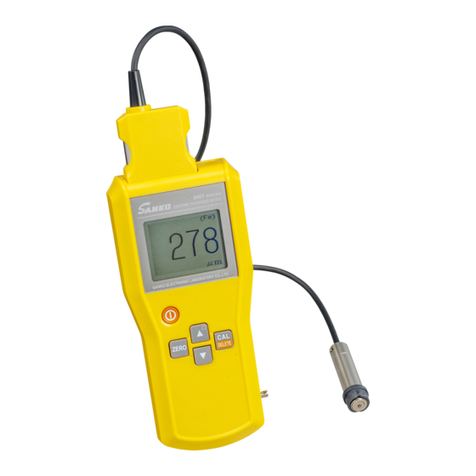
SANKO MR-300 User manual

MULTIFUNCTION TYPE
MOISTURE METER
MR-300
ELECTRIC MOISTURE METER
INSTRUCTION MANUAL
CAUTIONS:
● Before using the Meter, read this INSTRUCTION MANUAL
thoroughly and use the Meter correctly.
● Keep this INSTRUCTION MANUAL carefully and refer to this
when necessary.
● Connect/disconnect the probe after surely confirming the
power OFF. It causes out of order.
● In the event of any doubt arising, the original INSTRUCTION
MANUAL in Japanese is to be final authority.
SANKO ELECTRONIC LABORATORY CO., LTD.
(株式会社 サンコウ電子研究所)

-1-
CONTENTS
ITEM PAGE
1.FEATURES AND APPLICATIONS 2
2.SPECIFICATIONS 3
3.NAME OF PARTS 5
3‑1 Instrument proper 5
3‑2 LCD display 8
3‑3 Standard probe 12
4.OPERATING INSTRUCTIONS 13
4‑1 Connecting (Disconnecting) the probe 13
4‑2 Power ON・OFF 13
4‑3 Various measuring methods 14
5.MEASUREMENT 15
5‑1 Preparation for the measurement 15
5‑2 Converting the measurement mode 16
5‑3 Converting the hold mode 17
5‑4 Setting upper and lower limit values 17
5‑5 Releasing upper and lower limit values 18
5‑6 Converting the key lock mode 18
5‑7 Printing out the measured data 18
5‑8 Releasing the printing out 18
5‑9 Communication with PC 18
5‑10 Releasing the communication with PC 18
5‑11 Communication with PC and printing out of the measured data 18
5‑12 Releasing the communication with PC and printing out 19
5‑13 Setting the memory mode 19
5‑14 Restoring the construction of the memory 20
5‑15 Erasingthememorizeddataintheblock 20
5‑16 Selecting the memory block 20
5‑17 Measurement in the memory mode and releasing 21
5‑18 Measurement in the memory mode and printing out 21
5‑19 Measurement in the memory mode and communication with PC 21
5‑20 Measurement in the memory mode, communication with PC and printing out 22
5‑21 Printing out the memorized data 22
5‑22 CommunicationwithPCofthememorizeddata 22
5‑23 Communication with PC and printing out the memorized data 23
5‑24 Graphically indicating the statistical data and the histogram 23
5‑25 Printing out the statistical data 23
5‑26 Printing out the histogram 23
5‑27 Communication with PC of the statistical data 23
5‑28 Communication with PC of the histogram 24
5‑29 Communication with PC and printing out of the statistical data 24
5‑30 Communication with PC and printing out of the histogram 24
6.MEASUREMENT IN THE MOISTURE CONTENT (MC) MODE 25
7.COMMUNICATION WITH PC 25
8.TEMPERATURE COMPENSATION 30
9.NOTES FOR THE MEASUREMENT 32
10.BATTERY 32
10‑1 Indication of the voltage drop 32
10‑2 Handling while the Meter is not in use 32
11.MAINTENANCE AND INSPECTION 32
12.MISCELLANEOUS 33
12‑1 How to use the Moisture reading checker (option) 33
12‑2 Cover for the needle electrode (Fitting/removing methods of the cover) 33

-2-
1.FEATURES AND APPLICATIONS
●The moisture contents for various materials/products can be measured with the probe connecting to the
instrument proper.
Kinds of the probe: probe for wood, probe for paper, probe for mortar and plaster
●The moisture contents of all kinds of objects can be compared in the MC mode.
Measurement can be carried out by converting the mode of the instrument proper keeping on each probe
connecting.
Select the probe to be connected in accordance with an electrical characteristic of an object to be
measured.
Classification and comparison of dry and moisture for the object can be easily and quickly checked as
these are displayed with values 1 to 100.
WOOD :Sewn lumber, wood for buildings, fittings, packing, plywood, compiled wood,
particle board, wood for furniture, flooring, textile wood, wood works such as
household goods
PAPER :Moisture control while storing and keeping of high quality paper, craft paper,
paper board, wall paper, corrugated paper, paper articles, used news paper,
used magazine, other used paper, etc.
MORTAR AND :Moisture control of mortar, concrete, plaster, etc.
PLASTER Quality control for coating, clothing, tiling, all kinds of water proofing, etc.
MOISTURE :Moisture control of fabric, food, chemical synthetic products, ceramic, etc.
CONTENT Moisture contents are indicated with a certain value, so that the object can be
judged by the comparison of the measured value.

-3-
2.SPECIFICATIONS
■MR-300 Instrument proper(Common specifications)
Measuring method DC electric resistance method
Measuring range Depends on connecting probe
Probe Selection for the objects
Conversion of mode Moisture %, MC mode (Moisture Content)
Resolution Moisture : 0.1 %
MC mode : 0.5, 1 (no unit)
Indication LCD display with hold function, measuring values,
kind of connecting probe, hold, upper and lower limit values,
printer, voltage drop etc.
With EL back light, kana/alphabet by conversion
Alarm Upper and lower limit values (setting only one limit value is also available)
Setting voluntary value with 0.1 % pitch
Memory Fixed 5 blocks × 3000 points or
Voluntary Blocks × No. of memory =15000 points(Max.)
Statistical treatment Indication and printing out the No. of measuring values, No. of data,
Max. value, Min. value, average value, median, highest frequent value,
standard deviation and histogram.
Communication Built-in RS-232C interface
Communication speed 19200, 9600, 4800, 2400, 1200, 600 bps
Printer Thermal paper with 58mm breadth
Compensation of temperature Automatic compensation of temperature with ON, OFF function
Power source Dry batteries R6P(1.5V) × 8 pcs. With auto power off function
(4 pcs. for controlling the instrument proper and 4 pcs. for the printer unit)
Continuously usable time is approx. 25 hours
Operating temperature 0 to 40 ℃(except dew condensing condition)
Dimensions and weight 103(W) × 41(H) × 228(D)mm, 740g
Accessories Cable for communication, AC adapter, Spare role paper for printer,
Carrying bag
Option Moisture reading checker
Neck Strap

-4-
■MR-300 Standard probe
●Probe for wood
Type TG-PA(Standard probe for wood)
Measuring range 3.5 to 50.0%
Hardwood(Hard)/Softwood(Soft) by conversion
MC-3(Moisture Content) by 1 to 100 indication
(1 to 50 : 0.5 pitch, Over 50 : 1.0 pitch)
Dimensions and Weight 50(W) × 30(H) × 135(D)mm, 320g
Accessories Hexagonal wrench, spare needle
●Probe for paper and corrugated board
Type KG-PA(Standard probe for paper and corrugated board)
Measuring range 3.5 to 40.0%
MC-2(Moisture Content) by 1 to 100 indication
(1to100:0.5pitch)
Dimensions and Weight 50(W) × 40(H) × 150(D)mm, 360g
Accessories Hexagonal wrench, spare needle
●Probe for mortar and plaster
Type PM-PA(Standard probe for mortar and plaster)
Measuring range 0.8 to 15.0%
Mortar/Plaster by conversion
MC-1(Moisture Content) by 1 to 100 indication
(1to100:1.0pitch)
Dimensions and Weight 50(W) × 30(H) × 130(D)mm, 310g
※We will prepare or fabricate the optional probe suitable to the object to be measured other than above
mentioned 3 kinds of the standard probe(PA type).
Please contact us at the nearest branch for details.

-5-
3.NAME OF PARTS
3‑1 Instrument proper
①Group key (GROUP)
Measurement mode is different depending on the connected probe.
The mode is converted each press of the key.
TG-PA:Measured value of the moisture in Wood (HARD/SOFT) and MC-3 mode are converted.
KG-PA:Measured value of the moisture in Paper and MC-2 mode are converted.
PM-PA:Measured value of the moisture in Mortar/Plaster and MC-1 mode are converted.
②Hold key (HOLD)
ON or OFF of the hold function is converted each press of the hold key.
The measured value is held until succeeding measurement in the hold ON state.
③Setting key of upper and lower limit values(H/L)
Place the key to the setting mode for upper and lower limit values.
Set an arbitrary value by using the setting key of the value ⑩.
④Lock key (LOCK)
By pressing the lock key, all keys except the power switch key ⑤are locked and misoperation
is avoided.
⑤Power switch key (POWER)
Switch for power source ON or OFF.
When the probe is not connected to the instrument proper, [PE] probe error is indicated on the display
and the power OFF. Power switch ON after surely connecting the using probe.
⑥Non Mem. Key
Key for releasing the memory mode.
The mode is converted to the measurement mode without memory.

-6-
⑦Mem. key
Key for setting the memory block.
⑧Com. key
Key for setting the communication mode with PC.
⑨Print key
Measuring data, statistically calculated result and histogram are printed out.
⑩Setting key of the values (「×」「 Ø」)
Key for setting the upper and lower limit values, selection of the memory and
setting the communication speed .
「×」「 Ø」key traverse 0.1% pitch and quickly advance(return) by keeping on keys pressing.
⑪Stat. key
Key for indicating the statistically calculated process and result of the memorized data.
No. of the data (No. of the data of the mother group), Max. value, Min. value, distribution range,
average value, median (middle value of numbers, but not the middle of value), highest frequent value
(highest frequent measured value), standard deviation(by means of the following formula)
SS =(χ1-n)
2
+(χ2-n)
2
+(χ3-n)
2
・・・・・・・ +(χY-n)
2
V=SS/n
Ans =√V
(χ= individual data, n =average value, SS =flat square, V =dispersion)
⑫Cancel key
Key for cancelling each mode such as print, statistical exercise and histogram.
and for suspending the setting operation on the way.
⑬Clear key
Key for restoring the memory block, erasing the memorized data and releasing upper and lower
limit values.
⑭Set key
Key for setting each mode such as「Mem.」,「Com.」,「Print 」.
⑮Hist.key
Key for indicating the process for drawing up and the result of the histogram of the memorized data.
⑯Feed key
Key for feeding the paper of the printer.
⑰LCD display
Kind of the connecting probe, measured values, upper and lower limit values, measurement mode,
[E]showing LOW-BATT, etc. are indicated.
⑱Receptacle for probe connector
Receptacle for connecting the probe.
⑲Battery case(lower backside of the instrument proper)
Batteries are contained in this case.
⑳Hook for neck strap
Be sure to fit the neck strap(option) and pass through the neck to prevent the Meter from dropping.
○
AProbe connector
Connector for connecting the probe to the instrument proper.

-7-
Receptacle for RS-232C
・Out-put port for RS-232C
・When the Meter is connected to
the instrument having the port
of RS-232C such as P.C., use the Button for the EL back light
attached communication cable for ・Button for switching ON the EL
RS-232C. back light to raise the visibility
in dark place.
Receptacle for connecting the AC adapter ・As the back light consumes a lot
・When the Meter is used in AC100V, of capacity of the battery, be careful
AC adapter is connected to this not to light it so long time.
receptacle.
・Be sure to use the attached exclusive
AC adapter, if necessary.
Adjusting dial of view angle
・Dial for adjusting the density of the
LCD display ⑰. The density becomes
dark by turning it leftwards and faint
rightwards.Adjust it to the easy
position to read.
Connector for Connector for the
the AC adapter RS-232C
Insert it in the Insert it in the receptacle
receptacle to the to the bottom placing the
bottom. arrow mark downwards.
dark light

-8-
3‑2 LCD display
a. Kind of the connecting probe
Display varies depending on the connecting probe and measurement mode as follows.
For Wood : TG-H, TG-S, MC-3
For Paper : KG, MC-2
For Mortar : MORTAR, PLASTER, MC-1
b. Setting of the communication with PC
When the communication function with PC is ON by the key operation, COM is displayed with the
selected communication speed.
This mark is erased in OFF condition.
c. Memory mode
When the memory mode such as storage or retrieve of the data to/from the memory is set,
Mem is displayed with the memory block number. When the no mode is set, this mark is not displayed.
d. Operation of printer
When the printer is in ON condition, Prt is displayed and not displayed in OFF condition.
e. Voltage drop of the instrument proper
When the voltage of the battery supplying the power to the electronic circuit of the instrument proper
drops until less than specific voltage, this mark is displayed.
When this mark is displayed, slide the cover of the battery space at the back side of the instrument
proper downwards and replace all four alkaline dry batteries for the control part of the instrument proper
placed in right hand with new ones quickly.
When replacing the batteries, turn OFF the power switch of the instrument proper before replacing.
If the dropped voltage is raised up to specific voltage with new batteries, the indicated mark disappears.
When the Meter is continuously used after voltage drop mark was indicated on the LCD display,
following conditions will occur.
・Though it differs depending on the characteristic and using condition of the dry batteries, the Meter
can work for several hours. (Replace all 4 batteries with fresh specified dry batteries earlier.)
・When the Meter is continuously used as it is, measured values will become unstable.
・When the power switch is turned ON, the buzzer continuously sounds and key operation become
impossible simultaneously. (Remove the batteries from the Meter.)
・When no indication is on the LCD display, the batteries are completely consumed.
h.Hold mode
g.Communication speed i.Upper limit value mark
j.Lower limit value mark
a.Connecting probe TG‑H HOLD H 20.0% k.Upper limit value
b.Comm. with P.C. COM:19200bps L 10.0% l.Lower limit value
c.Memory mode Mem:Blk. 150 № 25 m.No. of
d.Operation of printer Prt measurement memory
e.Voltage drop of the
instrument proper
f.Voltage drop of printer E P
n.No. of memory block
o.Measured value

-9-
f. Voltage drop of the printer
When the voltage of the battery supplying the power to the mechanical part and control part of the
printer drops until less than specific voltage, this mark is displayed. (Displayed only while operating the
printer)
When this mark is displayed, slide the cover of the battery space at the back side of the instrument
proper downwards and replace all four alkaline dry batteries for the printer unit part placed in left hand
with new ones quickly.
When replacing the batteries, turn OFF the power switch of the instrument proper before replacing.
If the dropped voltage is raised up to specific voltage with new batteries, the indicated mark disappears.
g. Indication of the communication speed
Communication speed of the data is displayed in the rate bit/second.
When the communication function with PC is OFF, the speed is not displayed.
h. Display of the hold mode
When the hold mode is set, [HOLD] mark is displayed and is not displayed in OFF condition.
i. Indicating mark of the upper limit value
When the upper limit value is set, [H] and the upper limit value are displayed together, and are not
displayed in un-setting condition.
j. Indicating mark of the lower limit value
When the lower limit value is set, [L] and the lower limit value are displayed together, and are not
displayed in un-setting condition.
k. Upper limit value
The input value with the keyboard or the upper setting value stored in the memory is displayed.
When no upper limit value is set, the value is not displayed.
l. Lower limit value
The input value with the keyboard or the lower setting value stored in the memory is displayed.
When no lower limit value is set, the value is not displayed.
m. Number of the measurement memory
When the initial block size is set, the memory capacity in one block is displayed.
While operating in the memory mode, memory number has been stored is displayed.
When no initial block size is set, the memory capacity is not displayed.
n. Number of the memory block
When the initial block size is set, total number of the blocks is displayed.
While operating in the memory mode, using block number is displayed.
When no initial block size is set, using block number is not displayed.
o. Indication of the measured value
Measured value is displayed.

-10 -
●Indicating function by kana
When the Meter is delivered, the Meter is set with LCD display/printing mode by alphabet.
But the Meter can be converted to LCD display/printing mode by kana.
By pressing the [Clear] key ⑬and [Cancel] key ⑫simultaneously, display and printing mode are converted.
By pressing these two keys again, the mode returns to the mode by alphabet.
Converted mode is remained even after power OFF.
So in case the Meter power ON next time, the Meter can be used with the converted mode at previous
power OFF condition.
Relation of the indication between alphabetandkanaisasperfollowinglist.
◎LCD Display
Indication by the alphabet Indication by the kana
TG‑H モクザイ‑H
TG‑S モクザイ‑S
KG カミ
PLASTER プラスタ
MORTAR モルタル
HOLD ホールド
COM: ツウシン
Prt プリント
Mem: メモリ
BLK. ブロック
fixed Block コテイガタブロック
User's format Block ユーザーセッテイガタブロック
stat. トウケイ
Total ゼンスウ
Max サイダイ
Min サイショウ
Range ハンイ
Mean ヘイキンチ
Median チュウオウチ
Mode サイヒンチ
S.D. ヘンサチ
Temp ON オンドホセイON
Temp OFF オンドホセイOFF
inhibit シヨウキンシ
X‑mit ソウシン
mem Overflow メモリオーバーフロー
Memory Clear メモリデータ ショウキョ
Restor サイセッテイ
Com Error ツウシンエラー
Erase ショウキョ
No Data データナシ

-11 -
◎Printing Indication by the alphabet Indication by the kana
TG‑H モクザイ‑H
TG‑S モクザイ‑S
KG カミ
PLASTER プラスタ
MORTAR モルタル
HOLD ホールド
COM: ツウシン
Prt プリント
Mem: メモリ
BLK. ブロック
H‑set ジョウゲン
L‑set カゲン
Statistics トウケイデータ
Memory Block No メモリブロックバンゴウ
Total Count ゼンスウ
Max. Value サイダイチ
Min. Value サイショウチ
Range ハンイ
Mean.Value ヘイキンチ
Median チュウオウチ
Mode サイヒンチ
Standard Deviation ヘンサチ(ヒョウジュンヘンサ)

-12 -
3‑3 Standard probe
Probe for Wood(TG-PA)
○
C○
B○
A
Probe for Paper(KG-PA)
○
C○
B○
A
Probe for Mortar and Plaster(PM-PA)
○
C○
B○
A
○
AProbe connector
○
BProbe cord
○
CElectrode Probe for Wood (needle electrode)
Probe for Paper (needle electrode + SB attachment)
Probe for Mortar and Plaster (rubber electrode)

-13 -
4.OPERATING INSTRUCTIONS
4‑1 Connecting(Disconnecting) the probe
(Be sure to confirm the power OFF.)
・To connect the probe:
Carefully insert the probe connector ○
Aof the
using probe to the bottom into the receptacle
for the probe connector ⑱.
・To disconnect the probe: ○
A
After confirming the power OFF, carefully pull
the probe connector ○
Areleasing the locks located
at both sides.
・If the cord is pull out of the receptacle without
releasing the locks, it causes breaking of the cord
or the connector.
※If the probe connector ○
Ais disconnected while
the power ON, it causes out of order.
4‑2 Power ON・OFF
・Press the power switch ⑤, then the kind of connected
probe is indicated on the LCD display ⑰with a
beeping sound.
(When no probe is connected, [PE] probe error is
indicated on the LCD display and the power goes off
with beeping sounds of the buzzer.)
・Press the power switch again, then the power OFF
after indicating [END] mark on the display with a
beeping sound.
・The batteries consumption caused by forgetting the
power OFF is prevented with the auto power OFF function.
When the measurement is not carried out continuously for about 3 minutes, the power will go off
automatically.
※When switching over the power switch ⑤ON or OFF, operate the switch with an interval of 3 to 5
seconds to prevent malfunction.
TG‑H
E
LLL
%

-14 -
4‑3 Various measuring methods
MR-300 can be used with the combination of the probes and the following functions as well.
When the Meter is used with the combination of the functions, it is necessary to set up each function.
Set up the necessary function only when the Meter is used.
1)Measurement →Indication of the data (Refer to 5‑1)
2)Measurement →Indication of the data and printing (Refer to 5‑7)
3)Measurement →Indication of the data and communication with PC (Refer to 5‑9)
4)Measurement →Indication of the data, printing and communication with PC (Refer to 5‑11)
5)Measurement →Indication of the data and store of the data in the memory (Refer to 5‑13,5‑16)
6)Measurement →Indication of the data, store of the datainthememoryandprinting(Referto5‑18)
7)Measurement →Indication of the data, store of the data in the memory and communication
with PC (Refer to 5‑19)
8)Measurement →Indication of the data, store of the data in the memory, printing and communication
with PC (Refer to 5‑20)
9)Printing of the stored data in the memory (Refer to 5‑21)
10)Communication with PC of the stored data in the memory (Refer to 5‑22)
11)Printing and communication with PC of the stored data in the memory (Refer to 5‑23)
12)Indication of the results statistically treated of the stored data in the memory (Refer to 5‑24)
13)Indication of the results statistically treated of the stored data in the memory and printing(Refer to 5‑25)
14)Indication of the results statistically treated of the stored data in the memory and communication
with PC (Refer to 5‑27)
15)Indication of the results statistically treated of the stored data in the memory, printing and
communication with PC (Refer to 5‑29)
16)Indication of the histogram drawn by the results statistically treated (Refer to 5‑24)
17)Indication of the histogram drawn by the results statistically treated and printing (Refer to 5‑26)
18)Indication of the histogram drawn by the results statistically treated and communication
with PC (data of values) (Refer to 5‑28)
19)Indication of the histogram drawn by the results statistically treated, printing
and communication with PC (data of values) (Refer to 5‑30)
※Notice: The Meter can be used with the hold mode only except 1) item above mentioned.
The Meter indicates [inhibit] (kana:シヨウキンシ) on the LCD display ⑰besides the hold mode and can
not be set. Be sure to press the [HOLD] key ②.
※Notice: The Memorized data processing
When the memorized data are processed such as printing out, communication with PC, erase of the
data, etc., the probe dealing with the memorized data must be connected,
otherwise the operation for the memorized data processing can not be carried out.

-15 -
5.MEASUREMENT
5‑1 Preparation for the measurement
1. Connect the probe suitable for an object (wood, paper, mortar and plaster) to be measured.
2. Power switch ⑤ON and confirm the indications on the LCD display ⑰.
For wood =[TG-H] For paper =[KG] For mortar and plaster =[MORTAR]
Example: In case of connection
of the probe for wood
★When the probe is not connected, probe error [PE] is indicated on the LCD display ⑰and the power
OFFwith3beepingsounds.
★When [PE] is indicated on the LCD display ⑰and power OFF with 3 beeping sounds though the
probe is connected, power ON again after 2 to 3 seconds.
★When [PE] is still indicated on the LCD display ⑰in spite of power ON again after 2 to 3 seconds as
above mentioned, it seems that the probe is out of order.
Please contact to the purchased agent or our sales office to repair.
★When the power switch ⑤ON keeping on the probe pressing against the object to be measured,
once [LLL] is indicated on the LCD display ⑰and the measured value is indicated in 3 to 4 seconds.
3. Press the「Group」key ①, select the mode suitable for the object to be measured.
Refer to 5‑2 Converting the measurement mode on page 16.
4. Press the electrode with a constant force against the object to be measured and read the indicated value
after settlement of the indication.
When the 2-needle electrode is used, thrust it to an object to be measured.
5. When the hold key ②is pressed, the indication on the display will be held at the time just removing
the electrode from an object to be measured.
Refer to 5‑3 Converting the hold mode on page 17.
Hold mode is released by pressing the hold key ②again.
※Note: In case the measurement is carried out with the probe hammered into the wood which is
an object to be measured:
Keep on the hold mode releasing until completion of the hammering of the probe.
Pay attention to convert the mode to the hold mode at the time when the measured value is read
after completion of the hammering.
(Whenthehammeringiscarriedoutinholdmode,it causes measurement error as the data during
hammering is held and indicated.)
TG‑H
LLL
%

-16 -
5‑2 Converting the measurement mode
・Normally the initial measurement mode of the selected probe is indicated on the LCD display.
・The measurement mode is converted each press of the「Group」key ①as shown in the following charts.
[Probe for Wood] Indication on the LCD
Power ON
Wood-Hard(Hard wood) TG-H
↓↓
Press [Group] key. Wood-Soft(Soft wood) TG-S
↓↓
Press [Group] key. MC mode MC-3
↓
Press [Group] key.
[Probe for Paper] Indication on the LCD
Power ON
Paper KG
↓↓
Press [Group] key. MC mode MC-2
↓
Press [Group] key.
[Probe for Mortar and Plaster] Indication on the LCD
Power ON
Mortar MORTAR
↓↓
Press [Group] key. Plaster PLASTER
↓↓
Press [Group] key. MC mode MC-1
↓
Press [Group] key.
・When power ON again after power OFF, the mode will automatically return to the mode at previous
power OFF condition.
★Be sure to confirm the measurement mode when the power is ON.

-17 -
5‑3 Converting the hold mode
When the hold key ②is pressed, the「Hold」mark is
indicated on LCD ⑰and indicated measured value will
be held until the next measurement.
Hold mode will be converted ON or OFF each press of
the key. [HOLD] is indicated on the LCD ⑰at ON of
the hold mode and no indication at OFF.
※When the「Hold」key ②is pressed while measuring
in later memory mode, the mode is converted to
NON-HOLD measuring mode and memory mode is released.
※Printing out, communication with PC and measurement in memory mode can not be set
with the indication「INHIBIT」on the LCD ⑰if the hold mode is not ON.
Handle the Meter after surely hold mode ON.
5‑4 Setting upper and lower limit values (in operating measurement mode)
H/L 「H」mark showing upper limit value is indicated blinking.
↓
×・ØInput upper limit value (omit in case of lower limit value only)
↓
H/L 「L」mark showing lower limit value is indicated blinking.
↓
×・ØInput lower limit value (omit in case of upper limit value only)
↓
H/L Mode returns to the measurement mode.
・When the upper and lower limit values are (Example) In case the upper and lower
set and the measured value exceeds set upper limit values for wood are set
limited value, 「H」and measured value are
indicated blinking by turns with beeping sounds. TG‑H HOLD H 20.0
For the value under set lower limit value,「L」L10.0
and measured value are indicated blinking by turns 16.7 %
with beeping sounds.
・When the setting condition of upper limit value and lower limit value are needed to change,
press the「H/L」key ③again and repeat above mentioned procedures.
※1.When no upper limit value is needed, after pressing「H/L」key ③at first, press「H/L」key again.
. In this case, as「H」mark showing upper limit value is erased and「L」mark showing lower limit
value blinks instead, set the lower limit value.
※2.When no lower limit value is needed, after setting the upper limit value, press「H」key ③
again while blinking「L」is indicating.
In this case, as「L」mark showing lower limit value is erased and only upper limit value is set.
※3.When the Meter is used in memory mode, carry out above procedure after selecting the store
memory block.
TG‑H HOLD
16.7 %

-18 -
5‑5 Releasing upper and lower limit values(in the operating measurement mode)
H/L
↓
Clear (Releasing both upper and lower limit values)
※When erasing of upper and lower limit values in the memory block is needed, repeat above
procedures after selecting the storage memory block.
5‑6 Converting the key lock mode
When the「LOCK」key ④is pressed, all keys except the power switch key ⑤are locked and
misoperation can be prevented.
ON mark showing key lock mode is not indicated on the LCD ⑰.
This mode can be released by power OFF.
5‑7 Printing out the measured data(Printing out at each measurement in the operating measurement mode)
◇Confirm the ON condition of the hold mode before pressing the key
Print 「Prt」is indicated blinking on the LCD.
↓← Cancel (When the setting is suspended)
Set Blinking「Prt」on the LCD stops.
5‑8 Releasing the printing out
Print 「Prt」is indicated blinking on the LCD.
↓
Cancel Indication of「Prt」on the LCD is erased.
5‑9 Communication with PC(Communication at each measurement in the operating measurement mode).
◇Confirm the ON condition of the hold mode before pressing the key
COM. [COM:XXXX bps] is indicated blinking on the LCD.
↓
×・Ø(Select the communication speed)
(Example) [19200bps] ←setting communication speed(blinking indication).
↓← Cancel (When the setting is suspended)
Set Blinking indication of [COM:XXXXbps] on the LCD stops.
5‑10 Releasing the communication with PC
COM. [COM:XXXXbps] is indicated blinking on the LCD.
↓
Cancel Indication of [COM:XXXXbps] on the LCD is erased.
5‑11 Communication with PC and printing out of the measured data
(Communication and printing out at each measurement in the operating measurement mode)
◇Confirm the ON condition of the hold mode before pressing the key
COM. [COM:XXXXbps] is indicated blinking on the LCD.
↓
×・Ø(Select the communication speed)
↓(Example)[19200bps] ←setting communication speed(blinking indication)
Set Blinking [COM:XXXXbps] on the LCD stops.
↓
Print 「Prt」is indicated blinking on the LCD.
↓※The order of [Com.] and [Print] is available also in reverse.
Set Blinking [Prt] on the LCD stops.
※In case of suspending before pressing the [set] key ⑭each, press the [Cancel] key ⑫.

-19 -
5‑12 Releasing the communication with PC and printing out
For releasing the communication with PC, refer to item "5‑10".
For releasing the printing out, refer to item "5‑8".
5‑13 Setting the memory mode
MR-300 can store up to Max. 15,000 data in the memory mode.
Therearefollowingtwowaysforsettingthememoryblock,soselectonewayofthetwoandsetthe
memory block.
The construction of the memory can not be changed on the way of the measurement.
Restore the construction of the memory and reset as shown in item "5‑14".
1. Fixed block system
5 blocks fixed system (3,000 data/1 block)
2. An arbitrary block construction system
This is a system to set the numbers of memory block and block size(numbers of the data storing
in 1 block) within Max. 15,000 data arbitrarily.
Max. number of the memory block will be 1,100 blocks and Min. of block size will be 10 data.
Memory can not be additionally constructed on the way even though the memory capacity is not full.
①Setting the fixed block(Memory block: 5, Number of memory: 3,000)
◇Confirm the ON condition of the hold mode before pressing the key
Mem. [Mem: Fixed Block] and [G:User's format Block] are indicated on the LCD ⑰.
↓
Mem. (Construct the fixed block) [Mem: BLK.1 No.---] is indicated blinking on the indicating
part of the memory condition.
↓←Cancel (When the setting is suspended)
Set The setting of the fixed block is finalized and blinking on the LCD stops.
[Mem: BLK.1 No.0] is indicated and the measurement can be done in the memory mode.
●Before measurement, confirm the measurement mode, press the [Group] key ①and change the mode
if necessary. After measurement, the block mode can not be changed.
②An arbitrary block construction system(Memory block × No. of memory ≦15,000)
◇Confirm the ON condition of the hold mode before pressing the key.
Mem. [Mem:Fixed Block] and [G:User's format Block] are indicated on the LCD ⑰.
↓
Group [Mem.BLK.----No.----] is indicated blinking on the indicating part
↓of the memory condition.
×・Ø(No. of the memory block)
↓(Example) [Mem.BLK.100] ←No. of block to be set(blinking indication)
Group [Mem.BLk.100 No.---] is indicated blinking.
↓(Blinking indication of Mem.BLK. 100 stops.)
×・Ø(Block size)
(Example) [No.150] ←Size of block to be set(blinking indication)
↓← Cancel (When setting is suspended)
Set Setting of the block construction is finalized and the blinking indication on the LCD stops.
[Mem:BLK.1 No.0] is indicated and the measurement can be done in the memory mode.
●Before measurement, confirm the measurement mode, press the [Group] key ①and change
the mode if necessary. After measurement, the block mode can not be changed.
※When the stored numbers in the memory reach the Max. data numbers while measuring in the memory
mode, the data is stored in the next empty block.
In case the data exist in the next block, the data will be stored in the third empty block.
If there are no empty block to store, the message [Memory Overflow] is indicated on the LCD ⑰and
the memory mode of the measurement is released.
Table of contents
Other SANKO Measuring Instrument manuals
SANKO
SANKO SWT-7200 II User manual

SANKO
SANKO SP-3300D User manual

SANKO
SANKO SWT-7000 III User manual
SANKO
SANKO PM-101 User manual

SANKO
SANKO SWT-7000 III User manual

SANKO
SANKO SAMAC-F User manual

SANKO
SANKO EDY-5000 User manual

SANKO
SANKO SM-1100 User manual

SANKO
SANKO MR-200 II User manual

SANKO
SANKO SWT-7200IV User manual