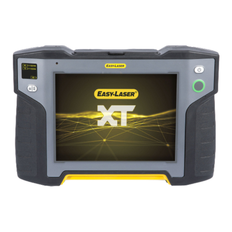
Easy-Laser E980 User manual

MANUAL
English
05-0602 Revision 1.0
System version 1.8
E980


CONTENT
INTRODUCTION 1
Service and calibration 3
DISPLAY UNIT 5
Navigation buttons 6
OK buttons 6
Function buttons 6
Status bar 7
Screen dump 8
LED signals 8
Battery 9
Charge the Display unit 9
Charge the Detectors 9
Calculator 10
Unit converter 11
Measurement le handling 12
Save le 12
Save le with barcode 12
Report 12
Open le 13
Open le with barcode 13
Open le as template 13
Copy le to USB memory 13
Download le to PC 13
Print le (Optional) 14
Control panel 15
Filter 15
Unit and resolution 16
Detector rotation 16
Date and time 16
Language 17
User 17
Backlight 17
Automatic power off 18
Information 18
VGA 18
System update 19
License 20
Bluetooth® 21

PROGRAM VALUES 23
Tolerance 24
Zoom 24
Half or Zero set value 25
Live values – colours 25
Automatic recording 26
Streaming values 27
Data format 27
STRAIGHTNESS 29
Show target 30
Show reference target 30
Measure 31
Quickmode 32
Add and delete points 33
Result 34
Result table view 35
Result 3D view 35
Result graph view 36
Tolerance 37
Calculation settings 38
Reference points 38
Best t operations 40
Waviness 41
Straightness settings 42
Show/hide horizontal values 42
Show history 42
Smooth/sharp graph 43
Waviness settings 43
SAWMILL 45
Saw blade 45
Bandsaw 46
TECHNICAL DATA 47
Display unit E51 48
Detector E5 49
Angular prism (Optional) 50
INDEX 51

1
INTRODUCTION
Damalini AB
Damalini AB develops, manufactures and markets Easy-Laser®measurement and
alignment equipment based on laser technology.
We have more than 25 years of experience from measurement tasks in the eld and
product development. We also provide measurement service, which means that we
ourselves use the equipment we develop, and continuously improve it. Because of this
we dare to call ourselves measurement specialists.
Do not hesitate to contact us about your measurement problems. Our expertise will
help you solve it in an easy way.
Declaration of conformity
Equipment: Easy-Laser®product range
Damalini AB declares that the Easy-Laser®product range is
manufactured in conformity with national and international regulations.
The system complies with, and has been tested according to the
following requirements:
EMC Directive 2004/108/EG
Low Voltage Directive 2006/95/EC
Laser Classication EN-60825-1 and complies with 21 CFR 1040.10 and 1040.11
except for deviations pursuant to Laser Notice No. 50,
dated June 24, 2007.
RoHs Directive 2002/95/EG
WEEE Directive 2002/96/EG
For Bluetooth®devices: This device complies with Part 15 of the FCC Rules.
Operation is subject to the following two conditions:
(1) this device may not cause harmful interference
(2) this device must accept any interference received, including interference that may
cause undesired operation.
Disposal of old electrical and electronic equipment (Applicable through-
out the European Union and other European countries with separate col-
lection programs)
This symbol, found on product or on its packing, indicates that this prod-
uct should not be treated as household waste when disposed of.
It should be handed over to an applicable collection point for the re-
cycling of electrical and electronic equipment. By ensuring this product is disposed
correctly, you will help to prevent potential negative consequences to the environment
and human health. For more detailed information about the recycling of this product,
please contact your local city ofce, household waste disposal service or the retail
store where you purchased this product.
Quality certicate
Damalini AB is ISO 9001:2008 certied. Certicate number 900958.
Damalini AB conrm, that our products are produced according to applicable national
and international regulations and standards. All components are checked before assem-
bly and nal products are tested in functionality and visually checked before delivery
The calibration of the equipment fully complies with ISO9001: 2008 #7.6

2
Introduction
Limited warranty
This product is manufactured under Damalini’s strict quality control system. Should
the product fail within two (2) years from the date of purchase under normal usage
conditions, Damalini will repair or replace the product free of charge.
Using new or refurbished replacement parts.1.
Exchange the product with a product that is new or which has been manufactured2.
from new or serviceable used parts and is at least functionally equivalent to the
original product.
Proof of purchase date should be conrmed, and sent together with a copy of the origi-
nal purchase document.
Warranty is valid under normal usage described in the user’s manual appended with
the product. The warranty comprises failure on Easy-Laser®product that could be
related to material and/or fabrication errors. The warranty is valid only in the country
of purchase.
The warranty is not valid in the following cases:
If the product is broken due to mishandling or incorrect operation•
If the product has been exposed to extreme temperature, calamity, chock or high•
voltage.
If the product has been modied, repaired or disassembled by unauthorized per-•
sonnel.
Compensation for possible damage due to failure on Easy-Laser®product is not in-
cluded in the warranty. Freight cost to Damalini is not included in the warranty.
Note!
Before delivery of the product for warranty repair, it is the responsibility of the buyer
to backup all data. Data recovery is not included in the warranty service and Dama-
lini is not responsible for data that may be lost or damaged during transit or repair.
Lithium Ion battery limited warranty
Lithium ion batteries inevitably lose power during their lifetimes, depending on usage
temperatures and the number of charging cycles. Therefore, the internal rechargeable
batteries used in the E-series are not included in our general 2-year warranty. There
is a 1 year warranty for the battery capacity not to fall below 70 % (a normal change
means that the battery must have more than 70 % capacity after more than 300 charg-
ing cycles). A 2 year warranty applies if the battery becomes unusable because of a
manufacturing fault or factors that Damalini AB could be expected to have control of,
or if the battery displays abnormal loss of capacity in relation to use.
Extended warranty
Easy-Laser® Measurement and Alignment Systems meet the highest quality standards!
For this reason, we have extended the warranty to you to a total of 3 years — free of
charge!
The prerequisite for a warranty extension is that you register your system parts on
the Internet within 6 months of purchase. The warranty period begins on the date of
purchase. The warranty extension applies to all products in accordance with the Easy-
Laser® Warranty requirements.

3
Introduction
Safety precautions
Easy-Laser®is a laser instrument in laser class II
with an output power less than 1 mW, which
requires the following safety precautions:
Never stare directly into the laser beam•
Never aim the laser beam at anyone else’s eyes.•
Note!
Opening the laser units can result in hazardous radiation, and will invalidate the
manufacturer warranty.
If starting the machine to be measured would result in injuries, the possibility to un-
intentionally start it must be disabled before mounting the equipment, for example by
locking the switch in the off position or removing the fuses. These safety precautions
should remain in place until the measurement equipment has been removed from the
machine.
Note!
The system should not be used in explosive risk areas.
Service and calibration
Our Service centres will quickly assist you if your measurement system need to be
repaired or when it is time for calibration.
Our main Service centre is located in Sweden. There are several local Service centres
that are certied to carry out limited service and repair. Contact your local Service
centre rst before sending your equipment for service or repair. All Service centres are
listed on our web site under Service and Calibration.
Before sending your measuring system to our main Service centre, please ll in the
online Service and Repair report. www.easy-laser-service.com

4
Introduction
Compatibility
The E-series is not compatible with previous analogue units from the D-series. You can
however continue to use previous brackets.
Disclaimer
Damalini AB and our authorized dealers will take no responsibility for damage to
machines and plant as a result of the use of Easy-Laser®measurement and alignment
systems.
Copyright
© Damalini 2012
We might change and correct the manual in later issues without further information.
Changes to the Easy-Laser®equipment may also affect the accuracy of the informa-
tion.
February 6 2012
Fredrik Eriksson
Quality Manager, Damalini AB
Damalini AB, PO Box 149, SE-431 22 Mölndal, Sweden
Web: www.damalini.com

5
DISPLAY UNIT
Navigation buttons
Function buttons
Numeric buttons
LED signals
OK buttons
AConnection for external power.
BNetwork connection. (Not available on all systems.)
CExternal connection. Use for projector for example. (Not available on all systems.)
DUSB A (master). Use for USB memory.
EUSB B (slave). Use for connecting to a PC.
FConnection for Easy-Laser® equipment.
GProtective cover.
A B C D E F
Battery compartment
(Not available on all systems.) G

6
Display Unit
Navigation buttons
To navigate on the screen, use the navigation buttons. The selected icon is marked with
a yellow frame. The navigation buttons are also used to move between the icons in a
submenu and to change the values in the elds.
Navigation buttons
Numerical buttons
OK button
OK buttons
There are two green OK buttons and they both work in the same way. Press OK to
select the currently selected icon for example.
Function buttons
The icons above the function buttons change depending on which view is currently
displayed on screen.
Function buttons
Below is a list of the most common icons.
Back to previous view. Press and hold to leave current program.
Back. There is no “previous view”. Leave the current program.
More. Contains a submenu with general functions,
such as (Control panel) and (Save le).
Submenus
The icons formed as an arrow contain a submenu. Use the navigation buttons to navi-
gate in a submenu. Press OK to select.
Function button with arrow contains submenu

7
Display Unit
Status bar
The Status bar contains additional information such as warning icon, current time and
Bluetooth®connection.
Measurement unit.
Change units via Settings.
The yellow arrow indicates
that there are sub-menus
There are also text messages regarding:
The selected icon.•
Hints on what information you are expected to ll in. •
Status bar icons
Warning. Select the function button to get additional information
regarding the warning.
Warning. Displayed when the coordinates has been rotated in the detector.
Go to Control panel to rotate coordinates.
Display unit charging. Indicating that a power adaptor is plugged in.
Hourglass. The Display unit is in the middle of a task.
Peripheral.
Indicates that a peripheral device is plugged in, such as a projector.
Bluetooth®. Indicates that the Bluetooth®functionality is activated.
The number beside indicates the number of Bluetooth®units connected.
Printing report on thermal printer. The thermal printer is optional equipment.
Printing performed OK.
Printing problem.

8
Display Unit
Screen dump
It is possible to take screen dumps of what is currently displayed on screen. You can
e-mail the screen dump or use it for reports.
Take a screen dump
Press and hold the numeric button period (.) for 5 seconds.1.
An hour glass is displayed on the status bar.2.
The screen dump is saved in the le system as a .jpg le. It is named with current 3.
date and time. Select to open saved les. See also Measurement le han-
dling.
LED signals
Right indicator
Yellow Flashing: The internal battery in the Display unit is charging.
Left indicator
Left indicator has several functions and colours:
Red/Blue Quick ashing: Reprogramming the system.
Red Flashing: Warning, for example low battery.
Blue Flashing: Searching for detectors equipped with Bluetooth®.
Fixed light: Connected to detectors equipped with Bluetooth®.
Green Flashing: Display unit is starting.
Fixed light: The internal battery in the Display unit is fully charged.
Light
blue
Flashing: Backlight is off, but the Display unit is still on. Press any
button to activate the Display unit.

9
Display Unit
Battery
Select to display the Battery view. This view gives you a good overview of the
battery status of all connected equipment.
Note!
When nished working for the day, charge the whole system. Plug in the power adap-
tor to the Display unit and connect the measuring units by using cable.
Charge the Display unit
The Display unit can be used from -10ºC to +50ºC. Charge the Display unit within the
temperature range of ±0ºC to +40ºC. You can charge the Display unit via:
Note!
If you shut the Display unit off while charging, it will charge faster.
Power adaptor
With the power adaptor plugged in, you can keep on working.
A PC via USB cable
While you have this connection, you can open the les in the
Display unit via the explorer in your PC. However, the Dis-
play unit is locked.
Dry cell batteries (Not available on all systems)
When you get a battery warning, insert four R14 dry cell batteries in the battery com-
partment. This ng the power of the Display unit so that you can nish your measure-
ment. However, if the internal battery is completely empty, the dry cell batteries do not
have enough power to start up the Display unit.
Charge the Detector/Measuring units
The Detectors and Measuring units are charged by the Display unit when connected by
cable. If you are using Bluetooth®units, switch to cable when the battery in the Detec-
tor/Measuring unit is low.
Charge the Bluetooth®units
The Bluetooth®units are powered by the Detector/Measuring units. To save energy, the
Bluetooth®units will only connect when you are using a measurement program. There
is no power switch on the unit. To switch off, simply unplug the unit. See also chapter
Bluetooth®.
Display unit
Dry cell batteries
Detector or
Measuring unit
Serial number
Battery charging
Battery pack
USB

10
Display Unit
Calculator
The calculator is found on the Start view and Control panel ( ).
Select1. and to open the calculator.
Use the numerical buttons and function buttons to enter values.2.
Use the3. OK button to compute.
Select to display sub-menu
Use OK button as equal sign (=)

11
Display Unit
Unit converter
The unit converter is found on the Start view and Control panel ( ).
Select1. and to open Unit converter.
Select a category. Move using the navigation buttons up and down.2.
Press navigation button right. The result column is activated.3.
Select a unit to convert from.4.
Enter an amount. The other units are recalculated.5.
In the example below, one inch is selected.
Select category Select unit and amount

12
Display Unit
Measurement le handling
Save le
Select1. and to save your measurement.
Enter a le name. The date and time will automatically be added to the le name. 2.
The measurements that you save will be available to other users as well.
Press3. OK to save the le.
Save le with barcode
The barcode scanner is not included in all systems. The rst time you measure a
machine, you stick a barcode on the machine and save the measurement together with
the scanned barcode. Next time you align the same machine, all you need to do is scan
the barcode and all machine data is read.
Scan the barcode on the machine.1.
Enter a le name. 2.
Press3. OK to save the le. All measure-
ment data is saved together with the
barcode.
The barcode number is added to the le name. When you connect the Display unit to a
PC the whole le name is shown:
Report
A report is generated and saved in the ling system. You can not open an old measure-
ment and save it again. You can however generate a new report from an opened le.
This means you can for example change the language and make a new report from the
opened measurement. You can download the report to a PC and print it.
Company logo
You can replace the logo on the report with your own .jpg le.
Name your logo1. logo.jpg. The default logo has the proportions of 230x51
pixels.
Connect the Display unit to your PC using the USB-cable.2.
Place your image in the Display unit’s folder3. Damalini/custom/reports/
logo.
File extensions (for example .jpg) are often hidden in the Explorer window. To dis-
play le extensions do the following: Open an Explorer window and press Alt to show
menu. Select Tools > Folder options. Click the View tab > Advanced settings > Clear
the Hide extensions for known le types check box.
Date format
By default, the date and time format is set to Central European Time (CET).
You can change the date and time format used in your PDF reports.
See also Control panel > Date and time.
File name
Barcode number
File name Barcode numberDate and time User Barcode reader

13
Display Unit
Open le
Select (found on the start view and Control panel) to open saved measurements.
The File manager is displayed. Here you can easily see who has saved the le, when
and from which program it was saved. You see les saved by all users.
xml
A measurement le. Select a
le and press OK to open.
jpg
A screen dump.
PDF
A report. The PDF report can not be
opened in the Display unit.
Open le with barcode
Start the Display unit and scan the barcode. The• latest measurement that was
made and saved with this barcode is automatically opened.
OR
Select• to open File view. Scan the barcode on the machine. All measure-
ments saved with this barcode are shown.
Open le as template
You can open a saved measurement and use it to make a new measurement. This is
very useful when you have many anges or machines with the same dimensions for
example. This way you do not have to enter the same distances every time.
Select1. (found on the Start view and Control panel). The File manager is
displayed.
Select a le in the list and select 2. . The Edit distance view is displayed.
Change distances if needed and proceed to measuring view.3.
Copy le to USB memory
You can easily copy a saved measurement or other les to a USB memory.
Insert a USB memory.1.
Select2. . The File manager view is displayed.
Select the le you want and select 3. .
A folder is automatically created on the USB memory. The le is saved in the 4.
folder \Damalini\archive\.
Download le to PC
Start the Display unit.1.
Connect the USB cable between the Display unit and PC.2.
While you have this connection, the Display unit is blocked.3.
View and/or copy the les to the PC. 4.

14
Display Unit
Print le (Optional)
Part no. 03-1004
The thermal printer is optional equipment.
Save the measurement. To print from a Shaft program, you need to open a saved1.
measurement before you can print a report.
Connect the thermal printer and select2. and .
The progress is displayed on the status bar.3.
Printing report on thermal printer.
Printing performed OK.
Printing problem.
You can also save a measurement, download the pdf-report to your PC and print the
pdf-report.
Report printed on thermal printer

15
Display Unit
Control panel
Select and to open the Control panel. Some of the settings are personal
and will be default next time you start the system.
File manager Calculator Battery
Back
Filter
Select to open the Filter view.
If the laser beam passes through air with varying temperature, this may inuence the
direction of the laser beam. If measurement values uctuate, this could mean unstable
readings. Try to reduce air movements between laser and detector by, for instance,
moving heat sources, closing doors. If the readings remain unstable, increase the lter
value (more samples will become available to the statistical lter).
Filter values
Use as short a time as possible that still produces acceptable stability during the mea-
surement. Default is set to 1. Normally you will use a lter value of 1-3. If you set the
lter type to 0, no lter will be used.
Filter view

16
Display Unit
Unit and resolution
Personal setting
Select to open the Units and resolution view. Use the navigation buttons to
move between the elds. Set Metric or Imperial and which resolution you want to use.
Default is set to 0.01 mm (0.4 mil). The selected unit is shown on the Status bar.
Unit and resolution view
Detector rotation
Personal setting
The coordinate system can be rotated 90º. Select to open the Detector rotation
view. When you have rotated the coordinates, a warning is displayed on the Status bar.
Detector rotation will only affect detectors with two axis.
Detector rotation view
Date and time
Select to open the Date and Time view. Set the date and time. Default is set to
Central European Time. (CET)
Date and time view
Select to set the date format used in your PDF reports.
Date and time used in PDF reports
Warning displayed on
Status bar
Table of contents
Other Easy-Laser Measuring Instrument manuals