Intellitec BBINT Series User manual

E11
BBINT Series User’s Manual
BBINT50A
DC/DC Charger
V0.5 03/11/2022

Contents
1. Safety Instruction
1-1 General Safety
1-2 Installation
2. General Information
2-1 Warranty
2-2 Disclaimer
3. Product Description
3-1 Dimensions
3-2 Optional Accessories
3-3 Features
3-4 Specification
4. Installation Instructions
5. Placement and Mounting
6. Connection
7. Configuration
7-2 Dip Switches
8. Operation
8-1 Battery Charger Operation Modes
8-2 LED Indicator
8-3 Charging Curve
9. Trouble Shooting
2
2
3
3
3
3
4
4
6
7
7
10
11
12
13
14
16
16
17
19
20
1
7-1 Default settings 14
7-3 RS-232 Programming 15
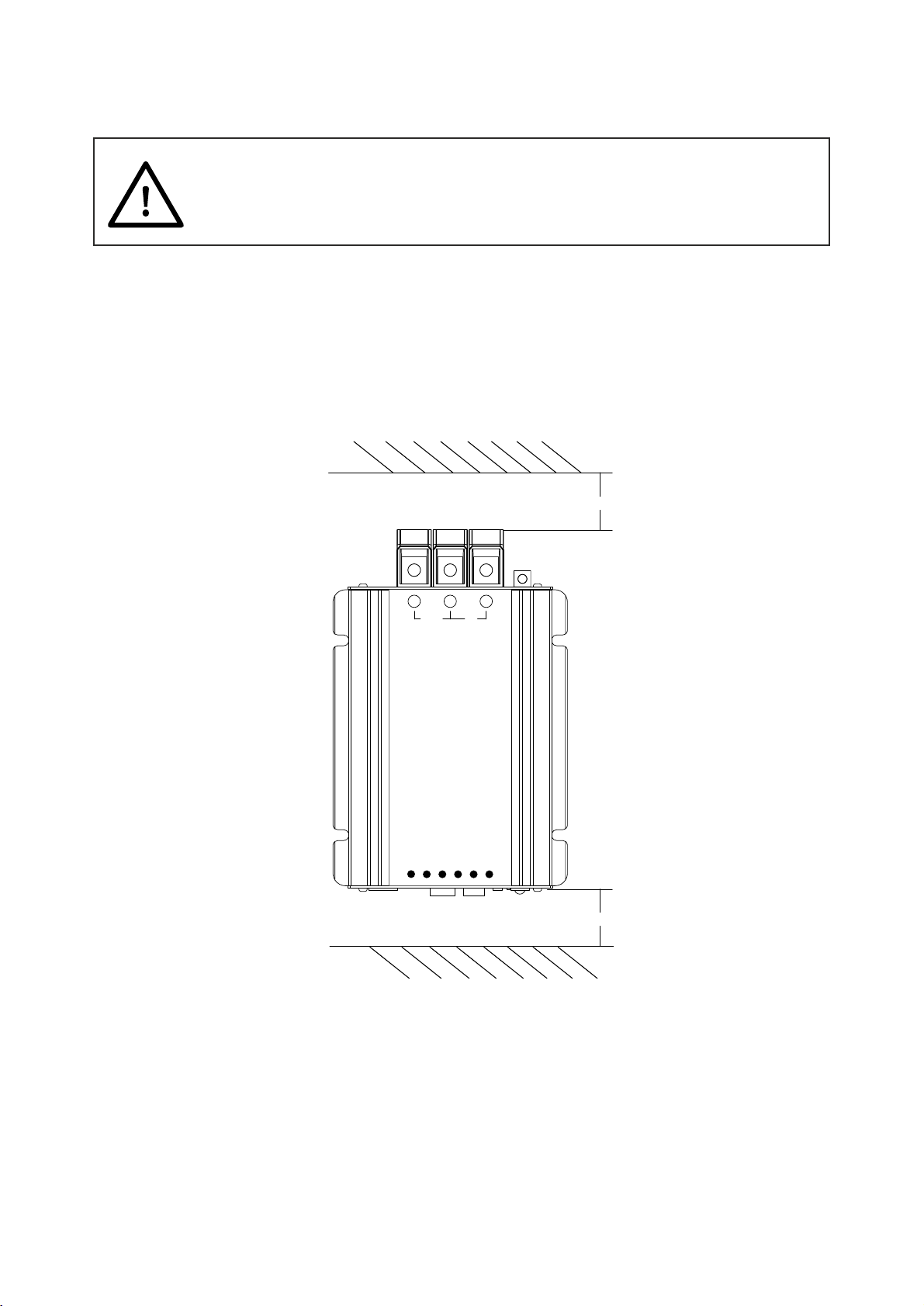
1. Do not expose the product to rain, snow, water mist or dusty environments to prevent
danger and malfunctions. Do not cover or block the ventilation holes of the product.
Keep a distance of at least 10 cm the Charger to allow air to circulate around
to help dissipate heat.
As shown below
flammable materials. appropriate length and cross section size Do not Install near Use
of cables (for details, see sections 4). Using inappropriate sized cables can
damage the product.
2. This product contains internal components that may cause arcing or sparking. To avoid fire or
explosion, do not install it in an enclosed space with batteries or flammable materials.
(Including any space containing gasoline-powered machinery, fuel tanks, fittings, accessories,
and other fuel system components) Do not install in the same location as a battery that could emit
explosive gasses. The produced by a being charged can be extremely corrosive gasses battery and
. Prolonged exposure may damage the product. explosive
Please read the user manual carefully before use and follow the instructions in the manual.
1-1 General Safety
WARNING
1. Safety Instruction
10CM
10CM
OUT
IN
+-+
Input Voltage
Output Voltage
Output Current
BMS
Ignition / Enable
Error
2

Installation environmental requirements
1. Dry - Do not place the product near water or in a humid environment that is prone to
condensation.
2. Temperature - Suitable for environments from -20 ° C to + 60 ° C.
3. Safety - Do not install in the same location as a battery that could vent explosive gasses
and do not install it near fire sources, flammable materials, fuel, generator equipment.
4. Ventilation - Leave a minimum of 10 cm clearance around the charger.
5. Dustproof - Do not install in dusty, wet, grinding or other harsh environments.
6. Avoid excessively long and under sized cable runs.
1-2 Installation
2. General Information
2-1 Warranty
2-2 Disclaimer
The warranty period of this product is two years. This is a return to base warranty. Please contact
warranty repairs. Please note warranty will only be accepted if the product has been used in the correct
manner as intended. Misuse including water, foreign objects, dust pollution, corrosion, tampering
or deliberate damage, will void warranty, and Intellitec MV Ltd will not be responsible for any
repairs. Product failures caused by misuse will be a chargeable repair.
Our products are subject to continual development and improvement. Therefore, additions or
modifications to the products may cause changes to the technical data and functional
specifications. No rights can be derived from this document. Please consult our sales representative
for current Terms & Conditions of Sale.
3. If the chemicals inside the battery come into contact with your skin or clothing, wash immediately
with plenty of soap and water. If the battery fluid gets into your eyes wash your eyes with
,
plenty of water for at least 20 minutes, and seek medical attention immediately.
4. Do not smoke or generate sparks near the battery.
5. When using metal tools, do not drop on the battery. If you accidentally drop it on the battery,
the battery may spark or cause a short circuit in the battery, which can cause the battery to
explode.
6. When installing the battery, remove metal items such as rings, bracelets, necklaces, and watches.
The short-circuit current caused by short-circuit of batteries is very high, can burn and
welding metals causing severe burns.
3
Avoid prolonged exposure to the gas atmosphere of the battery.
Intellitec MV for a Return Authorisation Number (RMA). Intellitec MV Ltd. is responsible for any

3-1 Dimensions
The BBINT50A charger converters a DC (battery) voltage to a regulated DC voltage. It can be used as a:
• 2-Stage battery charger or
• DC power supply.
The BBINT50A can only be used in installations with a negative ground.
Unit: mm
193 37
34 125
7
150
130
44
CN1 LIN
REMOTE
RS-232 TEMP.
0 1
S1
S2
S3
S4
S6
S7
S8
S5
OUT
IN
+-+
Input Voltage
Output Voltage
Output Current
BMS
Igni�on / Enable
Error
136.5
3. Product Description
4
• 3-Stage battery charger or
5
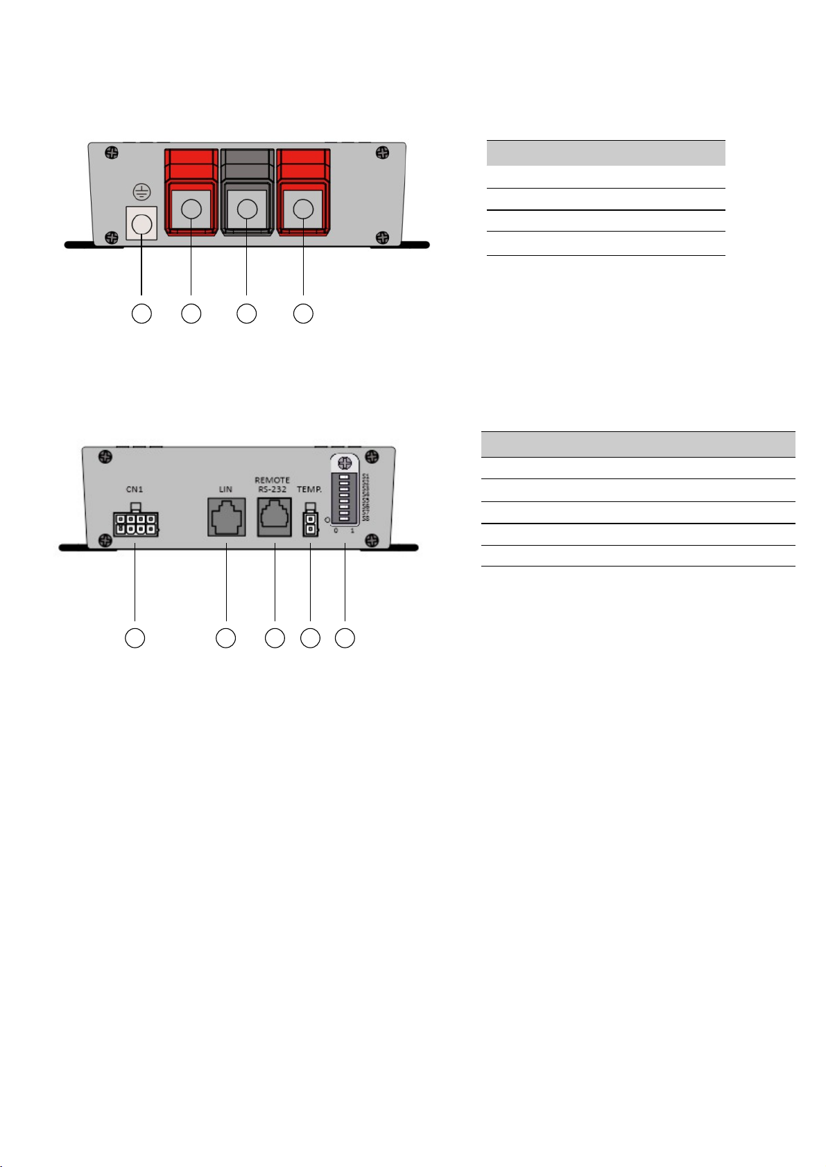
Front Panel
Rear Panel
1
2
3
4
Front Panel
INPUT
OUTPUT
PE
COMMON NEGATIVE
Rear Panel
CN1
LIN (For Future Use)
Remote Port (Programming Port)
Battery Temperature Sensor
DIP Switches
1
2
3
4
5
3 1 4 2
1 2 3 4 5

Charging Curve with Battery Temperature Compensation
U Rer 20°C
-3.33mv / °C per cell
12Volt system : -10mv / 0.5 °C
Temperature compensation characteristic
(charge voltage versus temperature)
52°C
12.0
12.5
13.0
13.5
14.0
14.5
15.0
-20 -10 0 10 20 30 40 50 60
Batery temperature (°C)
Charging voltage (V)
14.8VDC
14.4VDC
14.0VDC
ABSORPTION
FLOAT
14.2VDC
13.4VDC
13.8VDC
* If at - Absorption = 14.4V and Float = 13.8V20°C
6
- Fitting Kit k449 inc 8 Way Molex Mini Fit Jr including 30cm Terminated cables/tails.
- Battery Temperature Sensor (Not included, to be ordered separately) part no. APP-TEMP
Descripon Diagram
Temperature
Sensor
(Oponal)
unit:mm
3-2 Optional Accessories
12.5
58.5
11
22
2.5
14
Length : A
φ8.5
Length (max)
A 4600mm
Please refer to graph for adjusted temperature compensated values
1. Ignion/Enable (Acve HIGH)
2. BMS+ Enable (Acve High)
3. BMS- Enable (Acve Low)
4. Voltage Sensor + (0-17V)
5. Charging Relay Common
6. Charging Relay Normally Open
7. OTA Relay Common
8. OTA Relay Common
Loose Terminals
- Programming Cable (Part NO. K447). The programming cable is to be used in conjunction with
Intellitec’s battery to battery charger GUI, which is available to download at the hyperlink below:
https://www.intellitecmv.com/pages/downloads
part no.
APP-TEMP

3-3 Features
• The converter can be fully programmed by DIP Switches or by RS-232 using
• Built-in battery rescue (pre-charging) function
• Compatible with Lead Acid, LiFePO4, Gel and AGM batteries
• High efficiency and high reliability
• Withstand 2G vibration test
• Advanced Protection Features
• Built-in Buck Boost Converter (12V to 12V)
• Voltage / Temperature Compensation with Battery Temperature Sensor (Optional)
- Input / Output Reversed Polarity Protection by fuse
- Input Over & Under Voltage Protection
- Output Over Voltage / Short Circuit Protection
- Internal Over Temperature Protection
3-4 Specification
MODEL BBINT50A
OUTPUT
Rated Power 750W
Absorpon Voltage
DIP S1
0 : 14.4V ±1%
1 : 14.7V ±1%
Float Voltage
DIP S2
0 : 13.5V ±1%
1 : 13.8V ±1%
Recharge Voltage
DIP S3
0 : 12V ±1%
1 : 12.8V ±1%
Charge Current
DIP S4
0 : 100%
1 : De-Rang 50%
Charging Control
DIP S6 & S5
00 : Charger 1 : bulk->absorpon->float->recharge
01 : Charger 2 : bulk->absorpon->OFF->recharge
10 : Power Supply 1 : Constant Voltage by DIP S2
11 : Power Supply 2 : Constant Voltage by DIP S3
Level DIP S7 N/A
Baery Type Lead Acid/LiFePO4/Gel/AGM/Program(DIP S8)
Fuse 35A x 2
INPUT
Voltage Range 10V ~ 17V ±1%
Efficiency (Max.) 92%
Parasic Curent
( Ignion OFF ) < 5mA
Type Baery / Alternator / DC Source
Fuse 35A x 3
7
Intellitec MV GUI software BBINT50, downloadable from Intellitec MV Website
• Low temperature cut off and heater control for LifePo4 (requires temperature sensor)

MODEL BBINT50A
Environment
Working Temperature 12V : -20 ~ +60℃(De-rang by case temperature)
Storage Temperature -40 ~ +85℃
Relave Humidity 95% , non condensing
Vibraon IEC68-2-6
Safety & EMC
Safety Standards EN62368
EMC Standards Meets CE
E-mark E11 / 10R06/00*11580*00
Protection
Output Baery
Reverse
Polarity reversed protecon shutdown by
auto- recovery
Output Baery
Under Voltage
<10V Rescue charge
Output Baery
Over Voltage
>17V Shutdown
Output Baery Over
Temperature
>52℃ +-5℃ Shutdown by baery temperature
sensor
Output Short Circuit 3 seconds connuous output <1 , after shutdown
Input Reverse Polarity reversed protecon by fuse
Input Under Voltage <10V Shutdown
Input Over Voltage >17V Shutdown
Charger Over
Temperature
Alarm by case temperature 60℃
De-rang by case temperature 65℃
Shutdown by case temperature 70℃
Others Dimension(WxDxH) 130mm x 193mm x 44mm
Weight (KG) 1.3KG
8

Rescue (pre
-charging) Curve:
6.25%
Output Current
(Func 15 Value)
Batery Voltage
10V 11V
Output Current
Charger Curve VS Case Temperature De-rating Curve:
-40 0
Case Temperature (°C)
10%
100%
65 70
60
(Over Temperature Alarm)
Charging Curve
9
4. Installation Instructions
Installation Steps:
1. Place and mount the BBINT50A, see chapter 5
2. Connect the BBINT50A, see chapter 6
3. Configure the BBINT50A, see chapter 7
Read the entire manual before installing the BBINT50A. Keep the manual in a safe location
for future reference.
Operating temperature range: -20 up to +60 ºC, >40 ºC derating power
[-4 up to +140 ºF, >40 ºF derating power].
Never use the BBINT50A at a location where there is danger of gas or dust explosions.
Never Mount the BBINT50A in such a way that airflow through the heatsink is
obstructed. This device requires a minimum of 10cm of clearance on every side.
Do not install the BBINT50A in the same compartment as gassing batteries. Do not mount
in the same area as batteries that might release corrosive sulphur fumes or explosive gasses.
Be sure that the output of the supplying source is switched off during installation. Also be sure
that no load is connected to the batteries during installation, to prevent hazardous situations.
Use cables with an appropriate size, see the following table.
•
•
•
•
•
CAUTION
Recommended cable sizes DC input/output
BBINT50A 16 mm2 [AWG 6] 16 mm2 [AWG 6]
Models Minimum cable size Input Minimum cable size Output
Min. 3 Nm – max. 5 Nm
10
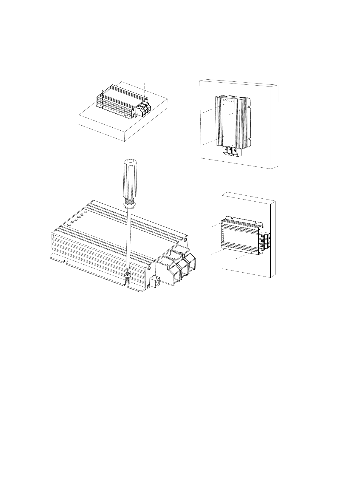
5. Placement and Mounting
Mount the BBINT50A with four M6 screws (7/32") to a solid flat surface.
11

Remote Switch Input
Ignition/Enable
Remote Switch Input
Ignition/Enable
6. Connection
• BBINT50A as a battery charger, see installation drawing A.
• BBINT50A as a stabilised DC power supply, see installation drawing B.
• Use properly sized fuses and wiring.
Installation Drawing A
Installation Drawing B
CN1 LIN
REMOTE
RS-232 TEMP.
0 1
S1
S2
S3
S4
S6
S7
S8
S5
LOAD
Battery Charger
Battery 1
(input)
5
1
2
1
0 1
5
1
Battery 2
(Output)
Battery Voltage
Sensor
IN OUT
PE
PE
LOAD
Stabilized
DC power supply
Battery
(input)
CN1 LIN
REMOTE
RS-232 TEMP.
0 1
S1
S2
S3
S4
S6
S7
S8
S5
5
1
IN OUT
PE
12
Battery Temp
Sensor
Ensure sufficient sized cable is used to common both Input Battery
and Output Battery Negatives together

7. Configuration
13
7-1 Default Settings
The default settings for the module are taken from the internal programming, and not the dip switches. In
order to configure the module using the dip switches, ensure dip switch 8 is in position 1. Dip switch 8 is the
toggle for the configuration settings, with 0 being the internal programmed settings, and 1 being the dip switch
settings (see 7-2 dip switches). The internal programmed settings that the module will arrive with can be found
in the table below. Please note that the dip switches provide basic parameter settings, while the GUI software
offers more advanced options. A programming cable (Part No.K447) will be required in order to use the GUI
software, which can either be purchased from Intellitec or made using the instructions on page 14 section 7-3.

Mode Charging Control
S6 S5
0 0
0 1
1 0
1 1
Charger mode 1
Charger mode 2
POWER mode 1
POWER mode 2
bulk→absorpon→float→recharge
bulk→absorpon→OFF→rechage (LiFePO4)
Constant Voltage by DIP S2
Constant Voltage by DIP S3
14
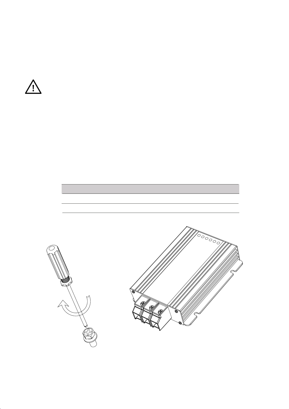
7-2 Dip Switches
The BBINT50 settings can be adjusted in two ways:
• By DIP switches (Basic parameters);
• Via RS-232/Intellitec MV GUI software (Basic parameters+advanced features/custom settings).
This chapter only describes the DIP switch settings
Use a small screwdriver to carefully set the required
settings. You may need to remove the BBINT cables
(or Terminator) to be able to access the DIP switches.
For an overview of the various DIP switch settings,
see the following three tables, where a 0 indicates
OFF or ↓ and a 1 indicates ON or ↑.
CN1 LIN
REMOTE
RS-232 TEMP.
0 1
S1
S2
S3
S4
S6
S7
S8
S5
0 1
S1
S2
S3
S4
S6
S7
S8
S5
Ensure DIP SW 8 is in position‘1' when using DIP switch settings.
Absorpon Voltage
0
S1
1
14.4V
14.7V
Float Voltage
0
S2
1
13.5V
13.8V
Recharge Voltage
0
S3
1
12V
12.8V
Charge Current
0
S4
1
100%
De-rang 50%

7-3 RS-232 Programming:
Please follow below drawing to make a communication cable. Alternatively this cable can be
To BBINT
RJ11 RS232
To Computer
1
6
Power Inverter RJ11 to RS232 RS232 to USB
RJ11 (Female) RJ11(Male) RS232(Female) RS232(Male)
PIN Descripon PIN Descripon PIN Descripon PIN Descripon
1 Not used 1 N/A N/A N/A
2 GND 2 GND 5 GND 5 GND
3 RX 3 RX 3 RxD 3 TxD
4 TX 4 TX 2 TxD 2 RxD
5 RMT 5 N/A N/A N/A
6 VCC 6 N/A N/A N/A
NA Seng
0 0
S7 S8
11
To Use Rs232 Programmed Sengs
To Use DIP S1-S7 Sengs
15
purchased through Intellitec MV

Temp:
CN1:
1 Ignion/Enable (Acve HIGH)
2 BMS+ Enable (Acve HIGH)
3 BMS- Enable (Acve LOW)
4 Voltage Sensor + (0-17V)
5 Charging Relay Common *
6 Charging Relay Normally Open *
7 OTA Relay Common
8 OTA Relay Normally Open
1 Temp.
2 GND
8. Operation
8-1 Battery Charger Operation Modes
Mode Explanaon
Charging
Standby
Alarm
Sleep
(low no-load power
consumpon)
The BBINT50A is in charging mode if it meets the switch-on
condions (see DIP wich/BBINT seeengs)
Possible error, connect BBINT50 and analyze the situaon
The BBINT50A goes to standby when is does not meet the
switch-on condions (see DIP wich/BBINT50 seengs)
Or
Switched off by the on / off button on in the BBINT50A menu or by a
BBINT50A event
The BBINT50A enters sleep mode when the sleep delay has
passed, to reduce the no-load power consumpon
Every 5 seconds, the BBINT50A scans if the configured baery
charger meets the switch-on condions
* Charger mode 2 : If the battery temperature is lower than 10 C, and the optional temperature
16
sensor is installed, the relay (CN1-PIN5 & 6) will close.(LiFePo4 for Heat Mat Control)
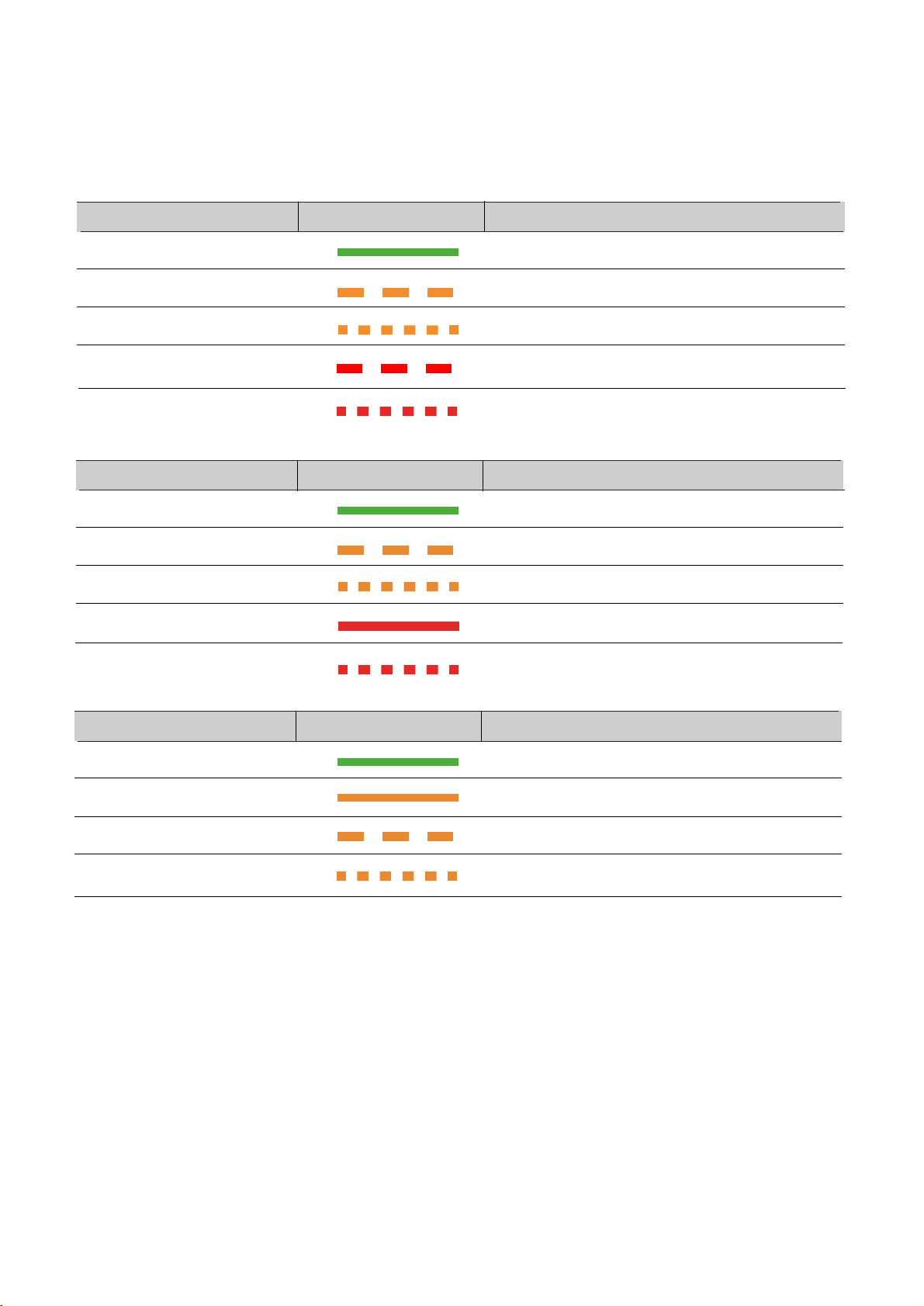
8-2 LED Indicator
Use the following table to understand the meaning of the diagnostic LED’s
Display LED:
Input Voltage
Output Voltage
Output Current
Green LED Solid
Green LED Solid
Green LED Solid
Orange LED Slow Flash
Orange LED Slow Flash
Orange LED Solid
Orange LED Fast Flash
Orange LED Fast Flash
Orange LED Slow Flash
Red LED Slow Flash
Red LED Solid Flash
Orange LED Fast Flash
Red LED Fast Flash
Red LED Fast Flash
No light
Normal
Normal
C.V. & Float
Under Voltage Alarm
Under Voltage Alarm
C.V. & Absorpon
Over Voltage Alarm
Over Voltage Alarm
C.C. & Bulk
Under Voltage Protecon Shutdown
Short Circuit Protecon Shutdown
C.C. & De-rang
Over Voltage Protecon Shutdown
Over Voltage Protecon Shutdown
Charging OFF
LED1
LED2
LED3
Status
Status
Status
17

BMS
Ignion
Error
Green LED Solid
Green LED Solid
Green LED Solid
Red LED Solid
No light
Orange LED Solid
Orange LED Slow Flash
Red LED Slow Flash
Red LED Solid
Orange LED Fast Flash
Red LED Fast Flash
No light
FUNC14 Seng 1
BMS+ > FUNC17 or BMS- Input to GND
Ignion Input Acon
Normal
FUNC14 Seng 1
BMS+ < FUNC17-0.3V & BMS- Input floaang
Ignion Input no signal
Input or Output Abnormal Alarm
FUNC14 Seng 0 (Default)
Baery Abnormal Temperature Alarm
Baery Abnormal Temperature Protecon
Shutdown
Charger Over Temperature Alarm
Charger Over Temperature Protecon Shutdown
Input or Output Abnormal Protecon
Shutdown
LED4
LED5
LED6
Status
Status
Status
18
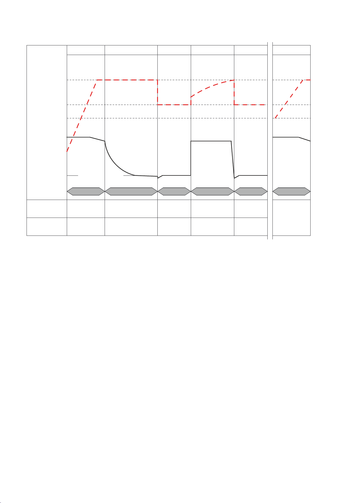
8-3 Charging Curve
BULK
2min~8hours
ABSORPTION
0.25hours~24hours
FLOAT
2weeks
FLOAT
2weeks
RECHARGE
85mins
BULK
2min~8hours
Voltage
Current
12.8
13.8
14.4
BULK(CC) ABSORPTION(CV) FLOAT RECHARGE FLOAT BULK(CC)
Return amps =6.25% of rated current
BULK
2min~8hours
ABSORPTION
0.25hours~24hours
FLOAT
2weeks
FLOAT
2weeks
RECHARGE
85mins
BULK
2min~8hours
Charging stage Reduce charging me by
charging at maximum current
(Constant Current)
Make sure the battery is fully charged
without overcharging (Constant Voltage)
Maintain the battery at
100% charge condion Recharging the battery Maintain the battery at
100% charge condion
Charging spec Charging at rated current 14.4V unl the curent drops to
6.25% of rated current Stay at 13.8V 14.4V with rated current Stay at 13.8V
Once battery voltage is below
12.8v, after 30
seconds, BBINT will turn from
FLOAT to BULK.
19
This manual suits for next models
1
Table of contents
Other Intellitec Batteries Charger manuals


