Intellitec BG40 User manual

Battery Guard
40 / 60 / 100 / 200
Owners Manual
Gebrauchsanweisung
Mode d'Emploi
Gebruiksaanwijzing
Battery Guard Owners Manual BG40 60 100 200 EN DU FR NL 151016
Ref : PM-AR-BP

Read the owners manual carefully before installing the BG!
Description
The Battery Guard BG40/60/100/200 (hereafter BG) is an intelligent, fully waterproof, battery guard with expansion capabilities for an on/off switch, alarm
buzzer or relay and our Battery Watch (not supplied). To ensure low losses, the BG is provided with two screw terminals, one Input+ and one Output+. The
rest, like the minus and the accessories are connected via four 6.3 mm faston connectors. The LED indicates the output status (on/off) of the BG and in the
programming mode the LED indicates the program position. The BG is provided with an 'Automatic board system detection' with which the BG automatically
detects what the battery voltage (12V or 24V) of the system is, so that it does not need to be set manually. Both under and over voltage thresholds can be
easily programmed.
Installation
Mount the BG on a cooling (metal) surface so that it can release the developed heat. Connect the BG as close as possible to the battery (maximum distance:
50cm). Only in this way can the voltage be monitored exactly. Any programming of the BG must take place before the equipment (users) can be connected. For
the minus connection use a cable of 1.5 mm2 which goes directly from the battery to the BG and do not use this connection for anything else.
Warnings
The product should only be connected by skilled fitters / mechanics, who are aware of the regulations for working with high battery voltages.
Live parts must not come into contact with the housing of the BG.
Use of bad material and / or too thin wires can damage the BG.
A short circuit between the positive and negative terminals of the battery may cause severe damage to your system.
Always use fuses (of the correct value).
Operation
In the standard programming (position 11 in the "Configuration Table") a buzzer may be connected to the alarm output. This will sound an alarm after 15
seconds when there is undervoltage. If the situation does not change, the BG will turn off attached devices after 60 seconds and the alarm will be switched off.
Since with overvoltage there is a risk of damage to the connected equipment this will be switched off immediately when there is overvoltage (16/32V) and the
alarm output will pulsate. This is done to distinguish between an undervoltage alarm and an overvoltage alarm.
A second application is to connect a relay to the alarm output. The BG must then be programmed in position 12 (see “Programming”). The relay will switch on
during an alarm and only switch off when reaching the reset value of the undervoltage. The relay can thus be used to activate a charger or generator.
Remote ON / OFF
You can connect a switch to the OFF terminal of the BG. If the OFF terminal is connected to the Minus the BG will immediately switch off the attached devices.
If the switch is opened again, the BG will switch on again after about 5 seconds. Since the current through the switch is zero (<10mA) a small switch can be
used.
Battery Watch (optional)
As can be seen in the connection diagram, there may be an optional Battery Watch connected. This is a simple battery status monitor which, by means of 3
LEDs, indicates the status of the battery. Please contact your dealer.
Programming Configuration Table
To start the programming mode a connection must be made
between the ProgramInput and Input+. The LED will flash. The
number of flashes indicates the program position (see table) that
the BG is in. As soon as the desired program position is reached
the connection (between the ProgramInput and the Input+) must
be broken. As confirmation the BG will repeat the number of
flashes. If it does not match your selection, you can repeat the
steps.
There are two types of settings that can be applied. Positions 1 to
10 adjust the threshold and reset values for ??an under voltage
alarm and the operation of the alarm can be set with positions 11
and 12. These settings must be made separately (one after
another).
When removing the battery voltage the programmed positions
remain retained. Once the programming is complete, the
equipment can be connected. First disconnect the battery
connection, connect the equipment to the Output+ and then
reconnect the battery.
Note
Before programming first disconnect the equipment from
the BG.
12 Volt mode 24 Volt mode
undervoltage reset undervoltage reset
Position 1* 10,50V 12,00V Position 1* 21,00V 24,00V
Position 2 10,00V 11,50V Position 2 20,00V 23,00V
Position 3 09,50V 11,50V Position 3 19,00V 23,00V
Position 4 11,25V 13,25V Position 4 22,50V 26,50V
Position 5 11,50V 13,80V Position 5 23,00V 27,60V
Position 6 10,50V 12,80V Position 6 21,00V 25,60V
Position 7 11,50V 12,80V Position 7 23,00V 25,60V
Position 8 11,80V 12,80V Position 8 23,60V 25,60V
Position 9 12,00V 13,00V Position 9 24,00V 26,00V
Position 10 10,00V 13,20V Position 10 20,00V 26,40V
alarm function alarm function
Position 11* Normal alarm Position 11* Normal alarm
Position 12 Relais function Position 12 Relais function
*→Default settings.
Normal alarm →Alarm output is activated in case of emergency: deactivation after 1 minute.
Relaisfunction →Alarm is activated in case of emergency: Deactivation upon reaching the reset voltage.
Battery Guard Owners Manual BG40 60 100 200 EN DU FR NL 151016

Technical details
BG40 BG60 BG100 BG200
Cable diameter 10mm215mm230mm250mm2
Automatic detection of 12V or 24V system 8-20V 12V mode→
20-35V 24V mode→
Asjustable undervoltage programs 10
Overvoltage disconnect voltage 12V mode 16V→
24V mode 32V→
Masimum load / shutdown approx 40A – 45A approx 60A – 65A approx 100A – 105A approx 200A – 210A
Surge 120A 240A 480A
Voltage drop 0,1V @ 40A 0,15V @ 60A 0,125V @ 100A 0,125V @ 200A
Current consumption Output active: 4mA
Output inactive: 2mA
Shutdown at overload / short circuit After 5 seconds. (Switch on again after 1 minute)
Voltage accuracy 2%
Current accuracy 20%
IP-code IP66
Dimensions (H*W*D) 82*41*65mm 61*112*120mm
Weight 185g 730g
Lesen Sie die Gebrauchanweizung zuerst aufmerksam, bevor Sie den BG ansließen!
Beschreibung
Der Battery Guard BG40/60/100/200 (abgekürzt bezeichnet als BG) ist eine intelligente, vollständig wasserdichte Batterieüberwachung mit
Erweiterungsmöglichkeiten wie Ein-/Aus-Schalter, Alarmsummer oder Relais sowie unserer Battery Watch (nicht im Lieferumfang enthalten). Um zu
gewährleisten, dass es nur zu geringen Leistungsverlusten kommt, wurde der BG mit zwei Bolzenanschlüssen ausgerüstet: einem Eingang (+) und einem
Ausgang (-). Der Rest wie der Minus-Anschluss und das Zubehör werden über vier 6,3 mm-Flachstecker angeschlossen. Auf der LED wird der Ausgangsstatus
(ein/aus) des BG angezeigt und im Programmierbetrieb zeigt die LED die Programmposition an. Der BG ist mit einer 'Automatic Boardsystem Detection'
ausgerüstet, durch die er selbst automatisch bestimmt, wie hoch die Batteriespannung (12V oder 24V) des Systems ist, sodass diese nicht von Hand eingestellt
zu werden braucht. Die Schwellenwerte für sowohl die Unter- als auch die Überspannung lassen sich ganz einfach programmieren.
Installation
Den BG an einer kühlenden Oberfläche (aus Metall) montieren, damit er die freigesetzte Wärme abgeben kann. Den BG so dicht wie möglich bei der Batterie
anschließen (Höchstabstand: 50 cm). Nur auf diese Weise kann die Spannung genau überwacht werden. Die mögliche Programmierung des BG muss
vorgenommen werden, bevor die Geräte (Benutzer) angeschlossen werden. Für den Minus-Anschluss ein Kabel (1,5 mm2) benutzen, das direkt von der Batterie
zu dem BG führt, und dieses Kabel bitte für keinen anderen Zweck verwenden.
Warnhinweise
Das Produkt darf ausschließlich von fachlich versierten Installateuren / Monteuren angeschlossen werden, die über die Vorschriften zur Arbeit mit
Batterien unter Hochspannung vertraut sind.
Spannung führende Teile dürfen niemals in Kontakt mit dem Gehäuse des BG kommen.
Bei der Verwendung von schlechtem Anschlussmaterial bzw. zu dünnen Drähten kann es zu Beschädigungen des BG kommen.
Ein Kurzschluss zwischen dem Plus- und dem Minus-Anschluss der Batterie kann zu schwerwiegenden Schäden Ihres Systems führen.
Immer Sicherungen (mit dem richtigen Wert) verwenden!
Funktionsweise
Bei der Standardprogrammierung (Position 11 in der „Konfigurationstabelle“) kann am Alarmausgang ein Summer angeschlossen werden, der bei einer
Unterspannung nach 15 Sekunden einen Alarm erzeugt. Sollte sich die Situation nicht verändern, schaltet der BG nach 60 Sekunden die angeschlossenen
Geräte aus; dabei wird auch der Alarm ausgeschaltet. Da bei einer Überspannung die Gefahr einer Beschädigung der angeschlossenen Geräte besteht, werden
sie bei einer Überspannung (16/32V) unverzüglich ausgeschaltet und gibt der Alarmausgang einen Impuls. Dadurch kann zwischen einem Unter- und einem
Überspannungsalarm unterschieden werden.
Eine zweite Anwendung ist der Anschluss eines Relais am Alarmausgang. Der BG muss dabei in Position 12 programmiert werden (siehe auch
“Programmierung”). Das Relais schaltet sich nun bei einer Alarmmeldung ein und erst dann wieder aus, wenn der Rücksetzwert der Unterspannung erreicht
wurde. Das Relais kann auf diese Weise zum Einschalten eines Ladegeräts oder Generators verwendet werden.
Remote ON/OFF
Am OFF-Anschluss des BG kann ein Schalter angeschlossen werden. Wenn der OFF-Anschluss mit Minus verbunden wird, schaltet der BG umgehend die
angeschlossenen Geräte aus. Wird der Schalter wieder freigegeben, schaltet sich der BG nach ca. 5 Sekunden wieder ein. Da der Strom durch den Schalter
praktisch null ist (< 10 mA), kann dafür ein kleiner Schalter verwendet werden.
Battery Watch (Option)
Wie im Anschlussschema gezeigt wird, kann als Option eine Battery Watch angeschlossen werden. Hierbei handelt es sich um eine einfache Anzeige zum
Batteriezustand, die anhand von 3 LEDs anzeigt, in welchem Zustand sich die Batterie befindet. Wenden Sie sich diesbezüglich bitte an Ihren Lieferanten.
Battery Guard Owners Manual BG40 60 100 200 EN DU FR NL 151016
Programmierung Konfigurationstabelle
Um den Programmierbetrieb zu aktivieren, muss eine Verbindung
zwischen ProgramInput und Input+ hergestellt werden. Die LED
blinkt jetzt. Die Anzahl beim Blinken zeigt an, in welcher
Programmierposition (siehe Tabelle) sich der BG befindet. Sobald
die gewünschte Programmierposition erreicht wurde, muss die
Verbindung (zwischen ProgramInput und Input+) aufgehoben
werden. Als Bestätigung wiederholt der BG die Anzahl beim
Blinken. Wenn dies nicht mit Ihrer Wahl übereinstimmt, können Sie
die Schritte wiederholen.
Zwei Arten von Einstellungen können vorgenommen werden: Mit
Position 1 bis 10 werden die Schwellen- und Rücksetzwerte für
einen Unterspannungsalarm eingestellt und mit Position 11 und 12
wird die Alarmfunktion eingestellt. Diese Einstellungen müssen
getrennt voneinander (nacheinander) vorgenommen werden.
Beim Freigeben der Batteriespannung werden die programmierten
Positionen beibehalten. Sobald die Programmierung vollständig ist,
können die Geräte angeschlossen werden. Dafür erst die
Batterieanschlüsse lösen, die Geräte an Output+ anschließen und
danach die Verbindung mit der Batterie wieder herstellen.
Achtung!
Vor dem Programmieren bitte erst die Geräte vom BG
trennen.
12 Volt betrieb 24 Volt betrieb
unterspannung zurück-
setzen
unterspannung zurück-
setzen
Positie 1* 10,50V 12,00V Positie 1* 21,00V 24,00V
Positie 2 10,00V 11,50V Positie 2 20,00V 23,00V
Positie 3 09,50V 11,50V Positie 3 19,00V 23,00V
Positie 4 11,25V 13,25V Positie 4 22,50V 26,50V
Positie 5 11,50V 13,80V Positie 5 23,00V 27,60V
Positie 6 10,50V 12,80V Positie 6 21,00V 25,60V
Positie 7 11,50V 12,80V Positie 7 23,00V 25,60V
Positie 8 11,80V 12,80V Positie 8 23,60V 25,60V
Positie 9 12,00V 13,00V Positie 9 24,00V 26,00V
Positie 10 10,00V 13,20V Positie 10 20,00V 26,40V
alarm funktion alarm funktion
Positie 11* Normaler alarm Positie 11* Normaler alarm
Positie 12 Relais funktion Positie 12 Relais funktion
*→Standardeinstellungen
Normaler alarm →Bei einem Alarm wird der Alarmausgang deaktiviert: Deaktivierung nach 1 Minute
Relaisfunktion →Bei einer Alarmmeldung wird der Alarm ausgelöst: Deaktivierung beim Erreichen der
Rücksetzspannung.
Technische Daten
BG40 BG60 BG100 BG200
Schnittfläche 10mm215mm230mm250mm2
Automatische Erfassung von 12V- oder 24V-System 8-20V 12V Betrieb→
20-35V 24V Betrieb→
Einstellbare Unterspannungsprogramme 10
Überspannung Abschaltspannung 12V Betrieb 16V→
24V Betrieb 32V→
Höchstbelastung / Abschaltung approx 40A – 45A approx 60A – 65A approx 100A – 105A approx 200A – 210A
Spitzenstrom 120A 240A 480A
Spannungsabfall 0,1V @ 40A 0,15V @ 60A 0,125V @ 100A 0,125V @ 200A
Stromaufnahme Ausgang aktiv: 4 mA
Ausgang inaktiv: 2 mA
Abschaltung bei Überlastung / Kurzschluss Nach 5 Sekunden (nach 1 Minute wieder einschalten)
Spannungsgenauigkeit 2%
Stromgenauigkeit 20%
IP-code IP66
Abmessungen (H*B*L) 82*41*65mm 61*112*120mm
Gewicht 185g 730g
Lisez attentivement le mode d'emploi avant de raccorder le BG!
Description
Le Battery Guard BG40/60/100/200 (nommé ci-après BG) est un protecteur de batterie intelligent, entièrement étanche, pourvu de possibilités d'extension pour
un commutateur marche/arrêt, un ronfleur avertisseur ou un relais, et notre dispositif de contrôle des batteries, le Battery Watch (non fourni). Afin de garantir
de faibles pertes, le BG est équipé de deux raccordements à écrou: un d'entrée+ et un de sortie+. Les autres connexions, comme celles du négatif et des
autres accessoires, sont réalisées au moyen de quatre cosses de Faston de 6,3 mm. Le voyant DEL indique la situation (marche/arrêt) du BG et dans le mode
programmation il indique la position du programme. Le BG est équipé du dispositif 'Automatic Boardsystem Detection', de sorte que la tension de la batterie
raccordée (12V ou 24V) est déterminée automatiquement et ne doit pas être réglée manuellement. Les seuils de sous-tension et de surtension peuvent
facilement être programmés.
Battery Guard Owners Manual BG40 60 100 200 EN DU FR NL 151016

Installation
Installez le BG sur une surface refroidissante (métallique) en mesure d'évacuer la chaleur produite. Raccordez le BG aussi près que possible de la batterie
(distance maximale : 50 cm). Ce n'est que de cette manière que la tension pourra être surveillée avec précision. La programmation éventuelle du BG doit être
effectuée avant que les appareils (utilisateurs) ne soient raccordés. Pour le raccordement à la borne négative, utilisez un câble de 1,5 mm2 qui relie directement
la batterie au BG et n'utilisez jamais ce raccordement pour un autre usage.
Avertissements
Le produit ne doit être mis en place que par des installateurs qualifiés, informés des prescriptions relatives au travail avec des dispositifs de haute
tension.
Les éléments d'alimentation ne doivent jamais entrer au contact du boîtier du BG.
L'utilisation de matériaux de connexion de mauvaise qualité et/ou de câbles trop fins peut endommager le BG.
Un court-circuit entre le raccord négatif et le raccord positif de la batterie peut gravement endommager votre système.
Utilisez toujours des fusibles (de puissance suffisante).
Fonctionnement
Dans la programmation standard (position 11 du “tableau de configuration”), un ronfleur peut être connecté à la sortie alarme. En cas de sous-tension, ce
ronfleur produit un signal d'alarme après 15 secondes. Si cette situation ne change pas pendant 60 secondes, le BG déconnecte les appareils raccordés, ce qui
déconnecte aussi l'alarme. Étant donné qu'une surtension constitue un risque d'endommagement des appareils raccordés, ceux-ci seront immédiatement
déconnectés en cas de surtension (16 V/32 V) et la sortie alarme émet des pulsations. Cela permet de distinguer une alarme de sous-tension d'une alarme de
surtension.
Une deuxième application consiste dans le raccordement d'un relais sur la sortie alarme. Le BG doit alors être programmé sur la position 12 (Voir
“Programmation”). En cas d'alarme, le relais est alors activé, puis désactivé lorsque la sous-tension atteint le niveau de réenclenchement. Le relais peut ainsi
être utilisé pour la mise en marche d'un chargeur ou d'un générateur.
Mise en MARCHE/ARRÊT à distance
Vous pouvez connecter un commutateur sur le raccordement ARRÊT du BG. Lorsqu'il y a liaison entre le raccordement ARRÊT et la borne négative, le BG
déconnecte les appareils raccordés. Si le commutateur est de nouveau ouvert, le BG reconnectera les appareils après 5 secondes. Étant donné que l'intensité
du courant dans le commutateur est nulle (<10 mA), il est possible d'utiliser un petit commutateur.
Contrôleur de batterie (optionnel)
Comme le montre le schéma de raccordement, un contrôleur de batterie (Battery Watch) peut être raccordé. Il s'agit d'un simple dispositif de surveillance de la
batterie, qui indique l'état de celle-ci au moyen de trois indicateurs DEL. Veuillez pour cela prendre contact avec votre fournisseur.
Programmation Tableau de configuration
Pour démarrer le mode programmation, une liaison doit être faite
entre l'entrée+ et l'entrée Programme. Le voyant DEL se met alors
à clignoter. Le nombre de clignotements indique dans quelle
position du programme (voir tableau) se trouve le BG. Dès que la
position souhaitée du programme est atteinte, la liaison (entre
l'entrée Programme et l'entrée+) doit être rompue. Le BG
confirmera le choix de position en répétant le nombre de
clignotements. Si cette position ne correspond pas à votre choix,
vous pouvez répéter ces étapes.
Deux types de réglages peuvent être réalisés. Les positions 1 à 10
permettent de régler les valeurs de seuil et de réinitialisation d'une
alarme de sous-tension et les positions 11 et 12 le fonctionnement
de la fonction alarme. Ces réglages doivent être effectués
séparément (l'un après l'autre).
Lors de la suppression de la tension de la batterie, les positions
programmées sont préservées. Les appareils peuvent être
raccordés dès que la programmation est achevée. Pour cela,
débranchez d'abord le raccordement à la batterie, raccordez les
appareils à la sortie+, puis rétablissez le branchement à la batterie.
Attention
Avant la programmation, débranchez les appareils du BG.
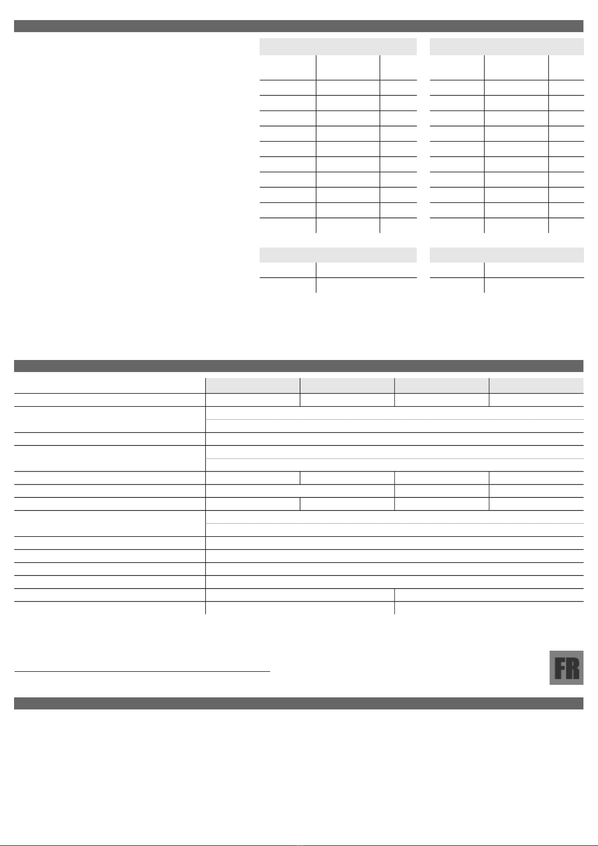
Modes 12 Volts Modes 24 Volts
Sous-tension Réinitia Sous-tension Réinitia
Position 1* 10,50V 12,00V Position 1* 21,00V 24,00V
Position 2 10,00V 11,50V Position 2 20,00V 23,00V
Position 3 09,50V 11,50V Position 3 19,00V 23,00V
Position 4 11,25V 13,25V Position 4 22,50V 26,50V
Position 5 11,50V 13,80V Position 5 23,00V 27,60V
Position 6 10,50V 12,80V Position 6 21,00V 25,60V
Position 7 11,50V 12,80V Position 7 23,00V 25,60V
Position 8 11,80V 12,80V Position 8 23,60V 25,60V
Position 9 12,00V 13,00V Position 9 24,00V 26,00V
Position 10 10,00V 13,20V Position 10 20,00V 26,40V
fonction alarme fonction alarme
Position 11* Alarme normale Position 11* Alarme normale
Position 12 Fonction relais Position 12 Fonction relais
*→Réglages standard.
Alarme normale →La sortie alarme est activée en cas d'alarme: désactivation après 1 minute.
Fonction relais →L'alarme est activée en cas d'alarme : Désactivation lorsque la tension de réinitialisation est
atteinte.
Battery Guard Owners Manual BG40 60 100 200 EN DU FR NL 151016

Spécifications techniques
BG40 BG60 BG100 BG200
Section [Diamètre] de câble 10mm215mm230mm250mm2
Détection automatique du système d'alimentation
(12V ou 24V)
8-20V mode 12V→
20-35V mode 24V→
Programmes de sous-tension réglables 10
Surtension de mise à l'arrêt mode 12V 16V→
mode 24V 32V→
Charge maximale / mise à l'arrêt env. 40A – 45A env. 60A – 65A env. 100A – 105A env. 200A – 210A
Courant de crête 120A 240A 480A
Chute de tension 0,1V @ 40A 0,15V @ 60A 0,125V @ 100A 0,125V @ 200A
Intensité absorbée Sortie active: 4mA
Sortie inactive: 2mA
Arrêt en cas de surtension / court-circuit (Remise sous tension après 1 minute)
Précision de la tension 2%
Précision du courant 20%
Code IP IP66
Dimensions (H*L*P) 82*41*65mm 61*112*120mm
Poids 185g 730g
Lees de gebruiksaanwijzing eerst aandachtig door alvorens de BG aan te sluiten!
Omschrijving
De Battery Guard BG40/60/100/200 (hierna te noemen BG) is een intelligente, volledig waterdichte, batterij bewaker met uitbreidingsmogelijkheden voor
aan/uit schakelaar, alarm zoemer of relais en onze Battery Watch (niet bijgeleverd). Om lage verliezen te waarborgen is de BG voorzien van twee bout
aansluitingen; één Input+ en één Output+. Het overige, zoals de minus en de accessoires, worden aangesloten via vier 6,3mm faston connectoren. De LED
geeft de output-status (aan/uit) van de BG weer en in de programmeermodus geeft de LED de programmapositie aan. De BG is voorzien van 'Automatic
boardsystem detection' waardoor de BG zelf automatisch bepaalt wat de accuspanning (12V of 24V) van het systeem is, zodat deze niet handmatig ingesteld
hoeft te worden. Zowel de onder- als overspanning drempelwaarden zijn op een eenvoudige manier te programmeren.
Installatie
Monteer de BG op een koelend (metalen) oppervlak zodat deze de ontwikkelde warmte af kan staan. Sluit de BG zo dicht mogelijk bij de accu aan (maximale
afstand: 50cm). Alleen op deze manier kan de spanning exact worden bewaakt. Het eventuele programmeren van de BG moet gebeuren voor de apparatuur
(gebruikers) aangesloten worden. Gebruik voor de minus aansluiting een kabel van 1,5mm2 welke direct van de accu naar de BG gaat en gebruik deze
aansluiting nergens anders voor.
Waarschuwingen
Het product mag alleen door vakbekwame installateurs / monteurs, die op de hoogte zijn van de voorschriften voor het werken met hoge accu
spanningen, worden aangesloten.
Spanningvoerende delen mogen nooit in aanraking komen met de behuizing van de BG.
Bij gebruik van slecht aansluitmateriaal en / of te dunne draden kan de BG beschadigen.
Kortsluiting tussen de plus en min aansluiting van de accu kan uw systeem zwaar beschadigen.
Gebruik altijd zekeringen (van de juiste waarde).
Werking
In de standaardprogrammering (positie 11 in “Configuratietabel”) kan er een zoemer aangesloten worden op de alarm-output. Deze zal bij onderspanning na 15
seconden een alarm geven. Als de situatie niet veranderd zal de BG na 60 seconden de aangesloten apparatuur uitschakelen, waarbij ook het alarm wordt
uitgeschakeld. Aangezien er bij overspanning kans is op beschadiging van de aangesloten apparatuur zal bij overspanning (16/32V) deze direct worden
uitgeschakeld en de alarm-output pulseren. Dit laatste zodat er onderscheid gemaakt kan worden tussen onderspanningsalarm en overspanningsalarm.
Een tweede toepassing is het aansluiten van een relais op de alarm-output. De BG moet dan geprogrammeerd worden in positie 12 (zie “Programmeren”). Het
relais zal dan inschakelen bij alarm en pas weer uitschakelen bij het bereiken van de reset waarde van de onderspanning. Het relais kan op deze manier
gebruikt worden voor het inschakelen van een lader of generator.
Remote ON/OFF
U kunt op de OFF aansluiting van de BG een schakelaar aansluiten. Als de OFF aansluiting met de Minus verbonden wordt zal de BG direct de aangesloten
apparatuur uitschakelen. Als de schakelaar weer wordt geopend zal de BG na ca. 5 seconde weer inschakelen. Aangezien de stroom door de schakelaar nihil
(<10mA) is kan hiervoor een kleine schakelaar gebruik worden.
BatteryWatch (optioneel)
Zoals in het aansluitschema te zien is, kan er optioneel een BatteryWatch aangesloten worden. Dit is een eenvoudige accu status monitor die door middel van 3
LEDs aangeeft wat de status van de accu is. Neem hiervoor contact op met uw leverancier.
Battery Guard Owners Manual BG40 60 100 200 EN DU FR NL 151016

Programmeren Configuratietabel
Om de programmeer modus op te starten moet er een verbinding
gemaakt worden tussen de ProgramInput en de Input+. De LED
zal gaan knipperen. Het aantal knipperingen geeft aan in welke
programma-positie (zie tabel) de BG zich bevindt. Zodra de
gewenste programma-positie bereikt is moet de verbinding (tussen
de ProgramInput en de Input+) worden verbroken. Ter bevestiging
zal de BG het aantal knipperingen herhalen. Indien het niet
overeenkomt met uw keuze kunt u de stappen herhalen.
Er zijn twee type instellingen die gedaan kunnen worden. Positie 1
t/m 10 stellen de drempel- en reset waarden voor een
onderspanning alarm in en met positie 11 en 12 kan de werking
van de alarm functie ingesteld worden. Deze instellingen moeten
los van elkaar (na elkaar) gemaakt worden.
Bij het loshalen van de accuspanning blijven de geprogrammeerde
posities behouden. Zodra de programmering compleet is kan de
apparatuur worden aangesloten. Haal hiervoor eerst de accu-
aansluiting los, sluit de apparatuur aan op de Output+ en herstel
daarna de verbinding met accu.
Let op!
Koppel vóór het programmeren eerst de apparatuur los
van de BG.
12 Volt mode 24 Volt mode
onderspanning reset onderspanning reset
Positie 1* 10,50V 12,00V Positie 1* 21,00V 24,00V
Positie 2 10,00V 11,50V Positie 2 20,00V 23,00V
Positie 3 09,50V 11,50V Positie 3 19,00V 23,00V
Positie 4 11,25V 13,25V Positie 4 22,50V 26,50V
Positie 5 11,50V 13,80V Positie 5 23,00V 27,60V
Positie 6 10,50V 12,80V Positie 6 21,00V 25,60V
Positie 7 11,50V 12,80V Positie 7 23,00V 25,60V
Positie 8 11,80V 12,80V Positie 8 23,60V 25,60V
Positie 9 12,00V 13,00V Positie 9 24,00V 26,00V
Positie 10 10,00V 13,20V Positie 10 20,00V 26,40V
alarm functie alarm functie
Positie 11* Normaal alarm Positie 11* Normaal alarm
Positie 12 Relais functie Positie 12 Relais functie
*→Standaard instellingen.
Normaal alarm →Alarm uitgang wordt geactiveerd in geval van alarm: Deactivatie na 1 minuut.
Relaisfunctie →Alarm wordt geactiveerd in geval van alarm: Deactivatie bij het bereiken van de resetspanning.
Technische gegevens
BG40 BG60 BG100 BG200
Kabeldiameter 10mm215mm230mm250mm2
Automatische detectie van
12V of 24V systeem
8-20V 12V mode→
20-35V 24V mode→
Instelbare onderspanning programma's 10
Overspanning afschakel spanning 12V mode 16V→
24V mode 32V→
Maximum belasting / afschakelen ca. 40A – 45A ca. 60A – 65A ca. 100A – 105A ca. 200A – 210A
Piekstroom 120A 240A 480A
Spanningsval 0,1V @ 40A 0,15V @ 60A 0,125V @ 100A 0,125V @ 200A
Stroomopname Output actief: 4mA
Output inactief: 2mA
Afschakelen bij overbelasting / kortsluiting Na 5 seconden. (Na 1 minuut weer inschakelen)
Spanning nauwkeurigheid 2%
Stroom nauwkeurigheid 20%
IP-code IP66
Dimensies (H*W*D) 82*41*65mm 61*112*120mm
Gewicht 185g 730g
Battery Guard Owners Manual BG40 60 100 200 EN DU FR NL 151016

Wiring diagram / Anschlusschema / Schéma des connexions / Aansluitschema
Battery Guard Owners Manual BG40 60 100 200 EN DU FR NL 151016
Battery Watch
(optional)
BATTERY
Consumers
Input+
Output+
Output+
Fuse
_+
_+
Prog.
Input
Alarm
Output Minus
Off
Input
On/Off
(Closed=Off)
Fuse 1A
Alarm
Buzzer
100/200
40/60
G
Ref : PM-AR-BP
This manual suits for next models
3
Table of contents
Languages:
Other Intellitec Batteries Charger manuals


Popular Batteries Charger manuals by other brands

Douglas Battery
Douglas Battery Legacy Operating and service instructions

Universal Power Group
Universal Power Group Jump Starters & Battery Charger Solutions brochure

AccuPower
AccuPower IQ216 user manual

CARLO GAVAZZI
CARLO GAVAZZI SBCLC 10A manual

4load
4load CHARGE BOX 3.6 user manual

MOB
MOB MO9653 user manual


