GARO ATLE User manual

GARO Atle
Quick Start
Box 203, SE–335 25 Gnosjö
Phone: +46 (0) 370 33 28 00
garo.se
GARO AB
manual 380265

2
ATLE CCS or CHAdeMO
ATLE CCS + CHAdeMO
1. Antennas
2. 7” touchscreen display
3. RFID reader
4. Connector support
5. Output Combo 2 DC connector
6. AC socket outlet Type 2
7. Emergency Stop button
8. Output cable
9.
10.
11.
Key locks
Connector support
Output CHAdeMO DC connector
1
1. Antennas
2. 7” touchscreen display
3. RFID reader
4. Emergency Stop button
5. Input cable
6. Output cable
7. Key locker
8. Connector support
9. Output DC connector
1
2
3
5
4
6
7
8
9
10
11
1
2
3
5
4
6
7
8
9

3Internal view
1. Optionnal modem board
2. RFID reader board
3. Modem board
4. Display board
5. OCPP board
1. Antennas
2. External fans for heat exchanger
3. Hood stand
4. Key locker
5. Input plate + cable gland
6. Emergency stop button
7. Heat exchanger
8. Extractor fan
9. Power module lid
10. CCU board
11. Distribution board
12. Output plate + cable gland
13. Key locker
4
1. Antennas
2. External fans for heat exchanger
3. Hood stand
4. Key locker
5. 12V power supply
6. AC powershare board
7. DC output cable glands
8. Heat exchanger
9. Extractor fan
10. Power module lid
11. CCU board
12. Distribution module
13. Key locker
14. Output Switch Board (OSB)
15. Input cable gland
1
2
3
5
4
6
7
8
9
10
11
12
13
14
15
5
1
2
3
5
4
6
7
8
9
10
11
12
13
1
23
5
4

1. Antennas
2. External fans for heat exchanger
3. Hood stand
4. AC input configuration board
5. Key locker
6. Input plate + cable gland
7. Emergency stop button
8. Heat exchanger
9. Extractor fan
10. 8kW Module - slave 1
11. 8kW Module - slave 0
12. 8kW Module - master
13. Distribution board
14. Output plate + cable glan
15. Key locker
6
Internal view - lower level
ATLE CCS or CHAdeMO
1. 8kW Module - slave 1
2. 8kW Module - slave 0
3. 8kW Module - master
4. AC input configuration board
5. Connection terminal block
6. Auxiliary contact relay
7. AC contactor
8. Transformer
9. Mechanical Circuit Breaker (MCB)
10. Output relays
11. CHAdeMO protection diode
12. Powermeter
7
Internal view - lower level
ATLE CCS + CHAdeMO
1
2
3
5
4
6
7
8
9
10
11
12
13
14
15
1
2
3
5
4
6
7
8
9
10
11
12

1. Antennas
2. External fans for heat exchanger
3. Hood stand
4. AC input configuration board
5. Key locker
6. Input plate + cable gland
7. Emergency stop button
8. Heat exchanger
9. Extractor fan
10. 8kW Module - slave 1
11. 8kW Module - slave 0
12. 8kW Module - master
13. Distribution board
14. Output plate + cable glan
15. Key locker
1. 8kW Module - slave 1
2. 8kW Module - slave 0
3. 8kW Module - master
4. AC input configuration board
5. Connection terminal block
6. Auxiliary contact relay
7. AC contactor
8. Transformer
9. Mechanical Circuit Breaker (MCB)
10. Output relays
11. CHAdeMO protection diode
12. Powermeter
Compliance
Derating
As a direct correlation exists between the current and ambient temperature a derating curve is provided for all
charging station.
Minutes before derating @ VOUT=370VDC & IOUT=65A
Max Power (%)

INSTALLATIONS
It is advisable to leave 1000mm free space on each side and 500mm on the top and the
bottom of the chargingstation if it is surrounded by a wall. This free space is mandatory for
charging station’s ventilation.
Never block the air flow.

1. The product benefits from manufacturer´s warranty. The applicable warranty period must be
stated in purchase documents from your supplier.
2. The product must be installed by a certified installer / contractor.
3. Proper installation, storage and operation conditions must be obtained.
4. Warranties apply only to products installed in their original installation location.
5. Installation, use, care, and maintenance must be normal and in accordance with instructions.
6. Warranty requires a dated, fully filled in Warranty form by an certified installer/contractor. If
the original installation date cannot be verified, then the warranty period begins ninety (90)
days from the date of product manufacture (as indicated by the model and serial number).
7. Warranty does not cover damage occurred by incorrect use of equipment, use of any non-
original spare parts, lack of maintenance or faults caused by disassembly of the product or
unauthorized persons intervention,
8. Warranty does not cover software or update thereof.
9. Warranty does not cover aesthetic deficiencies caused by negligent manipulation or
accidents (breaks or damage to the carcass).
10. Warranty does not cover damage caused by external overvoltage from either grid or car/
charging object.
11. Warranty does not cover damage caused by force major like for example but not limited
to: floods, winds, fires, lightning, accidents, sabotage, military conflicts, terrorism, volcanos,
earthquakes or corrosive environments.
SVERIGE/SWEDEN
Garantivillkor enl ALEM 09.
Garantin gäller ej om produkten varit utsatt för ett isolationstest, sk meggning.
WARRANTY CONDITIONS
EU COUNTRIES (EXCEPT SWEDEN)

1
EN
TABLE OF CONTENT
INFORMATION 3
ABOUT THE MANUAL 3
SAFETY NOTES 4
SPECIFICATION 5
TECHNICAL SPECIFICATION 6
HANDLING AND STORAGE INSTRUCTIONS 10
UNPACKING 11
GARO ATLE CCS OR CHADEMO 12
GARO ATLE CCS + CHADEMO 12
WALLBOX INSTALLATION 13
GUN HOLDER INSTALLATION 14
GARO ATLE CCS OR CHADEMO 15
GARO ATLE CCS + CHADEMO 15
ELECTRICAL CONNECTION 16
AC INPUT CONFIGURATION 16
ELECTRICAL CONNECTION GARO ATLE CCS OR CHADEMO 16
ELECTRICAL CONNECTION GARO ATLE CCS + CHADEMO 18
COMMISSIONING 22
OPERATING INSTRUCTIONS 24
UTILIZATION 24
ERRORS 30
PROTECTING THE ENVIRONMENT 32

INFORMATION
The information provided in this documentation contains general
descriptions and/or technical characteristics of the performance of
the products contained herein. This documentation is not intended
as a substitute for and is not to be used for determining suitability
or reliability of these products for specific user applications. It is
the duty of any such user or integrator to perform the appropriate
and complete risk analysis, evaluation and testing of the products
with respect to the relevant specific application or use thereof.
Neither GARO nor any of its affiliates or subsidiaries shall be
responsible or liable for misuse of the information contained
herein. If you have any suggestions for improvements or
amendments or have found errors in this publication, please
notify us.
You agree not to reproduce, other than for your own personal,
noncommercial use, all or part of this document on any medium
whatsoever without permission of GARO, given in writing. You
also agree not to establish any hypertext links to this document
or its content. GARO does not grant any right or license for the
personal and noncommercial use of the document or its content,
except for a non-exclusive license to consult it on an “as is” basis,
at your own risk. All other rights are reserved.
All pertinent state, regional, and local safety regulations must be
observed when installing and using this product. For reasons of
safety and to help ensure compliance with documented system
data, only the manufacturer should perform repairs to components.
When devices are used for applications with technical safety
requirements, the relevant instructions must be followed.
Failure to use GARO software or approved software with our
hardware products may result in injury, harm, or improper
operating results.
Failure to observe this information can result in injury or equipment
damage.
Document scope
ABOUT THE MANUAL
Technical documentation is an integral part of a product. Until it is
disposed of, always keep the technical documentation close to the
unit at hand, as it contains important information. Provide technical
documentation to the person concerned if you sell, assign or lend
the product.
This guide aims to provide informations needed for the use of the
GARO ATLE CCS /+ CHAdeMO. This guide must be read in
integrality with others related documents. This guide is intended for
users of the charging stations.
This guide concerns the following charging stations:
• GARO ATLE CCS
• GARO ATLE CHAdeMO
• GARO ATLE CCS + CHAdeMO
• GARO ATLE CCS + CHAdeMO + AC
• GARO ATLE CCS IT
• GARO ATLE CHAdeMO IT
• GARO ATLE CCS + CHAdeMO IT
• GARO ATLE CCS + CHAdeMO + AC IT
We invite you to write us to communicate any inaccuracies or
omissions, or to make general comments or suggestions regarding
the quality of this manual.
EN
2

SAVE THIS MANUAL
To ensure proper and safe operation, please read
these user instructions carefully and keep them for future
reference.
This manual contains important instructions for the DC
quick charger that shall be followed during installation,
operation and maintenance of the unit.
This equipment shall be installed, adjusted, and serviced
by qualified electrical personnel familiar with the
construction and operation of this type of equipment and
associated hazards.
The locking key, supplied with unit, should be kept in a
secure and known location by an individual that has read
and understands the content of this manual.
Do not open the front cover at any time while input power
is present.
Notes
Cautions
Do not operate the unit while the cabinet door is opened
or unlocked.
Failure to follow these instructions may result in death,
serious injury or equipment damage.
Warnings
RISK OF ELECTRIC SHOCK, INJURY, AND/OR
BURNING
Only qualified, trained and authorized people will
repair, replace or adjust this equipment.
Make sure the AC input breaker is OFF and measures
0V before the breaker.
Do not use this product if the cables (input or output)
are frayed, have damaged insulation
or any other signs of damage.
Do not use this product if the enclosure or the EV
connectors are broken, cracked, opened or show any
other indication of damage.
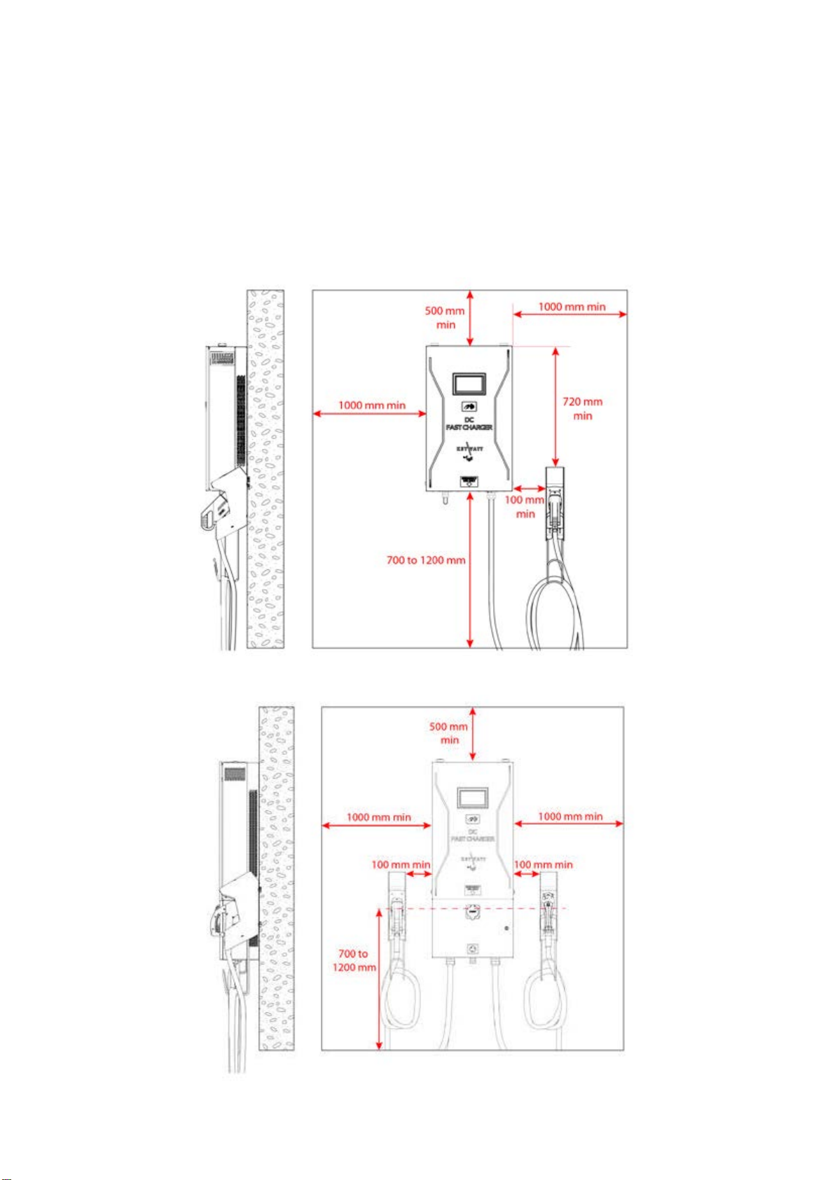
This equipment employs parts, such as switches
and relays, that tend to produce arcs or sparks and
therefore, when used in a garage, locate in a room
or enclosure provided for the purpose or not less than
500 mm (18 inches) above the floor.
Failure to follow these instructions can result in death or
serious injury
SAFETY NOTES
Read these instructions carefully, and look at the equipment
to become familiar with the device before trying to install,
operate, or maintain it. The following special messages may
appear throughout this documentation or on the equipment to
warn of potential hazards or to call attention to information that
clarifies or simplifies a procedure.
RISK OF DAMAGE TO THE TERMINAL
Do not use this product if the cables (input or output) are
frayed, have damaged insulation or any other signs of
damage.
Do not use this product if the enclosure or the Electrical
Vehicle Supply Equipment (EVSE) connectors are broken,
cracked, opened or shows any other indication of
damage.
Do not use a cord extension set or second cable assembly
in addition to the cable assembly for the connection of the
EV to the EVSE.
This equipment is not intended for use in residential
environments and may not provide adequate protection to
radio reception in such environments.
Failure to follow these instructions may result in serious
injury or equipment damage.
3
EN

Main supply
Mains supplies 3-phase P1/P2/P3 + N + GND 3x400V AC
Mains 3-phase voltage range V AC 400 V AC ± 10%
Earthed electrical system TT or TN
Frequency range f 50 Hz ± 10%
Nominal input current I AC 40-37 A Nom
Maximum input current I AC 45 A Max
Power Factor PF 0,99 Nom
Efficiency η95% Nom
Harmonic current @ nominal network voltage THDi < 13% Max
SPECIFICATION
Mains supplies 3- phase P1/P2/P3+GND 3x208-240V AC
Mains 3-phase voltage range V AC 208-240 V AC ± 10%
Earthed electrical system
IT earthed electrical system prohibited for AC charging
TT, TN or IT
Frequency range f 50 Hz ± 10%
Nominal input current I AC 72-63 A Nom
Maximum input current I AC 80 A Max
Power Factor PF 0,99 Nom
Efficiency η95% Nom
Harmonic current @ nominal network voltage THDi < 13% Max
EN
4

Internal AC input protection
Inrush current limitation per phase I INRUSH LIMIT < 3 x I AC Max
Rated Current Fuse (per module) I BREAK Rating 80 A typ
Breaking capacity of fuses I BREAK Capacity 80 000 A Max
Max earth leakage current I LEAKAGE < 3,5 mA Max
Emergency button connection Yes
Overvoltage (IEC60664-1) OVC III
Insulation protection Class (IEC60664-1) Class I
TECHNICAL SPECIFICATION
Internal DC Output
Output voltage V DC_max 530 V DC Max
V DC_ min 150 V Min
Output current I DC_max 65A (1)(2) Max
I DC_min 1,5 A Min
Max Output Power P OUT 24 kW Max
Output connector (charging station side) Permanent mounting
Car Plug connector Plug #1 CCS
Plug #2 CHAdeMO
Output cable length - 3,50 Meters
AC output for GARO ATLE CCS + CHAdeMO + AC only
AC output
AC Output voltage V AC_nom 400 V ± 10%
AC Output current I AC_max 32 A Max
Max Output Power P OUT 22 kVA Max
Car Plug socket Plug #3 AC type 2 socket
Type of connection Case “B” connection (mode3)
Detachable cable
General & dimensions
External dimensions (mm) H x W x D 860 x 507 x 250 mm (CCS or CHAdeMO)
1225 x 507 x 250 mm (CCS + CHAdeMO)
Weight (without cable, or bracket) kg 66 kg (CCS or CHAdeMO) Max
93 kg (CCS + CHAdeMO) Max
Type of installation Mounting on a wall or on a pedestal with proper fixation point
Fixation points 8 screws
Protection type (EN60529) IP IP55
Cooling systems Heatsink with forced air flow by fans IP55 without air filter
Noise (1m, all direction) Db(A) 65dbA (1m)
5
EN

Climatic & Environment constraints
Operating temperature (with derating) -25°C to +55°C(3)
Storage temperature -25°C to +60°C
Relative humidity RH 10% to 95%
Installation altitude Alt 2 000 m Max
Internal DC output protection
Hardware and software short circuit protection Yes
Software and Hardware over voltage protection adjustable +10% max
Over temperature protection - 70 °C
Reverse polarity protection Yes
DC output Contactor Yes (2 poles)
Rated Current Fuse (output) I FUSE 125 A
Galvanic isolation Vinput / output 5200 VDC
Max time for DC line discharge < 60V T<60V 1 s
Internal AC output protection
Inrush current 230A during 100 µs
30A during following second
Short circuit Socket I²t A²s 75 000
Circuit breaker for AC circuit 50A curve C
Max time for DC line discharge < 60V T<60V 1 s
Embedded Insulation device of charger module
Response time (tan) < 3sec. for asymmetrical fault
< 62sec. for symmetrical fault
Self test time At power on and every 60s during charge
Internal resistance Ri of the measuring circuit 1.5Mohms permanent
750Kohms continuous measurement
300Kohms during simultaneous switching measurement
Measurement method Continuous and switching measurement resistor method
Measuring current Im < 1,4mA at RF=0
Measurement range (Ran) 20Kohms…300Kohms
Relative uncertainty ±15%
Line L+/L- Voltage (Un) DC 150V…530V
System leakage capacity Ce ≤1µF : response value (Ran) and time (tan) are not guaranteed for
capacity above 1µF
Parallelization
Do not connect the insulation monitor device (IMD) in parallel!
Response value (Ran) and time (tan) are not guaranteed.
EN
6

Radio Frequency characteristics
The equipment module is designed to provide customers with global network coverage on the connectivity of UMTS/HSPA+, and it is
also fully backward compatible with the existing EDGE and GSM/GPRS networks.
Connectivity GSM/GPRS UMTS/HSPA+
Frequency Bands GSM900: Tx=880 MHz to 915MHz,
Rx=925 MHz to 960 MHz /
DCS1800: Tx=1710 MHz to 1785 MHz,
Rx=1805 MHz to 1880 MHz
3G band 8: Tx=880 MHz to 915MHz,
Rx=925 MHz to 960 MHz /
3G Band 1: Tx=1920 MHz to 1980 MHz,
Rx=2110 MHz to 2170 MHz
Power Output GSM900: 33.0dBm
DCS1800: 29.3dBm
23.06dBm for 880-915MHz
21.92dBm for 1920-1980MHz
RFID reader characteristics
To start a charge, users must swipe a contactless RFID card across the card reader.
Frequency Bands 13.553–13.567 Mhz
Power Output -6.67dBuA/m@10m
Norms & standards
EC Low voltage EC directive (LVD) 2014/35/EU
EC Electromagnetic Directive (EMC) 2014/30/EU
Radio Equipment Directive (RED) 2014/53/EU
Efficient use of Radio Spectrum (RED) ETSI EN 301 511 V12.5.1
ETSI EN 301 908-1 & -2 V11.1.1
ETSI EN 300 330 v2.1.1
Electric vehicle conductive charging system part 1
General requirement
IEC 61851-1
7
EN

Norms & standards
Electric vehicle conductive charging system part 22
AC Electric vehicle charging station
IEC 61851-22
Electric vehicle conductive charging system part 23
DC Electric vehicle charging station
IEC 61851-23
Electromagnetic compatibility (EMC) EN 61000-6-2
EN 61000-6-4/A1
EN 301489 v2.2.0
EN 301489-17 V3.2.0 of 2017
EN 61000-3-11
EN 61000-3-12
Insulation Monitor Device (IMD) IEC 61557-1 & IEC 61557-8
RoHS 2011/65/EU
Declaration of conformity CE(4) Yes
EV Ready Pending
(1) Max output current will be adapted versus maximum carrying current of the vehicle plug.
(2) Output current can be even reduced with the power derating versus temperature.
(3) Potential derating above 35°C.
(4) CE marking affixed on the product attest the conformity of the product with applicable requirements of relevent Community
harmonization legislation.
EN
8

HANDLING AND STORAGE INSTRUCTIONS
The charging stations are supplied in individual wood crate.
When commissioning the product, all the protection for transport
must be removed before energization.
Keep the charging station in its original packaging in an
appropriate place:
placed on dry ground or on a sheet to protect it from damp,
sheltered from dust, inclement weather and sunlight.
Storage temperature: -25°C to +60°C
Humidity: 10% to 95%
During prolonged storage, check the state of the charging station
packaging regularly.
Do not store the charging station for more than a year without
powering it up, to avoid the deterioration of
non-energized electronic components.
Storage
Transport
Throughout the transport phase, take all necessary measures to
keep the pallet stable.
Equipment Handling
GARO ATLE CCS or CHAdeMO charging station is a 66kg
equipment,
GARO ATLE CCS + CHAdeMO 93 kg. It must be handled by
two people minimum.
RISK OF INJURY DUE TO DROPPING OR FALLING
Follow specified procedures for hoisting operations.
Take measures to prevent falling when you carry or
transfer the unit.
Failure to follow these instructions will result in minor or
moderate injury.
RISK OF DAMAGE TO THE CHARGING STATION
Do not lift charger by the door. Damage will occur.
Improper storage or handling may cause damage to the
unit.
Failure to follow these instructions can result in equipment
damage.
Notes
Warnings
9
EN

UNPACKING
1. Remove the brackets holding the lid in place and lift the lid and
sidewalls upwards.
2. Remove the lid of crate. You will use it to put the charging
station.
3. Remove the T30 screw (x1) to remove the side panel. 4. Remove the M6 nuts (x3) on bracket’s studs with a 10mm
socket.
EN
10

7a. Remove the charging station from its bracket.
Note: Charging station must be handled by two people minimum.
7b. Remove the charging station from its bracket
Note: Charging station must be handled with lifting
equipment.
GARO ATLE CCS or CHAdeMO GARO ATLE CCS + CHAdeMO
11
EN

1. Using bracket as a template, level and mark drill holes.
2. Place the anchors and attach the bracket to the wall with
screws (x8).
3. Lift the charging station onto its mounting bracket.
Warning: Due to the charger weight, two people or lifting
equipments are required to lift and handle the charging station.
WALLBOX INSTALLATION
Wall mounting
4. Tighten the M6 nuts (x2) on bracket’s studs.
Recommended torque: 4 Nm
5. Place the side panel and fix it with its T30 screw
Recommended torque: 3 Nm
Drill bit for M6 screws / anchors for M6 screws (x8) / drill / spirit level / chalk
For mounting the wallbox on a pedestal see separate installation manuals DIM016055 (GARO ATLE CCS or CHAdeMO) or
DIM016197 (GARO ATLE CCS + CHAdeMO). For wall mounting follow the instructions below.
EN
12

GUN HOLDER INSTALLATION
Wallbox mounting
1. Clean the surface with isopropyl alcohol.
2. Wipe the surface with a clean cloth.
3. Leave to dry 1min. 4. Screw by hand the positioning pins FXVIS018322 (x2)
5. Peel the adhesive protection on the gun holder bracket.
6. Place the gun holder bracket on the side of the Wallbox,
aligned with its positioning pins.
7. Remove the positioning pins (x2).
8. Fix the bracket with its T30 screws (x2).
9. Press the bracket during 2min.
10. Let stand 1h minimum
13
EN
This manual suits for next models
9
Table of contents
Other GARO Batteries Charger manuals

GARO
GARO ENTITY PRO User manual

GARO
GARO GLB User manual

GARO
GARO Wallbox GLB+ User manual

GARO
GARO GLB****-B series Installation instructions

GARO
GARO Castra User manual

GARO
GARO LS4 Wallmounted Supplement

GARO
GARO ENTITY PRO Owner's manual

GARO
GARO QC45 User manual

GARO
GARO GHL User manual

GARO
GARO Twinbox GTB Series User manual
Popular Batteries Charger manuals by other brands

Insignia
Insignia NS-GXBOCK101-C2 Quick setup guide

Bosch
Bosch GML 50 Professional Original instructions

TecMate
TecMate Optimate 7 Select Instructions for use

Schumacher
Schumacher SE-1072 Important safety instructions

VENOM
VENOM Dual 3 Cell AC/DC LiPo Balance manual

Energic Plus
Energic Plus SMC user manual