Inter Water INTER HEAT SMART 115IS Service manual

IMPORTANT SAFETY INSTRUCTIONS
Read and follow all instructions
V.010822
HEAT PUMP INTER HEAT SMART
MODELS: 115IS / 140IS
Installation & Instruction Manual
HidroShop.mx

2
INTER HEAT SMART
115IS / 140IS
/CONTENTS
1. PREFACE
2. SPECIFICATIONS
2.1 PERFORMANCE DATA OF SWIMMING POOL HEAT PUMP UNIT
2.2 DIMENSIONS FOR SWIMMING POOL HEAT PUMP UNIT
3. INSTALLATION AND CONNECTION
3.1 INSTALLATION ILLUSTRATION
3.2 SWIMMING POOL HEAT PUMPS LOCATION
3.3 HOW CLOSE TO YOUR POOL
3.4 SWIMMING POOL HEAT PUMPS PLUMBING
3.5 SWIMMING POOL HEAT PUMPS ELECTRICAL WIRING
3.6 INITIAL START-UP OF THE UNIT
4. USAGE AND OPERATION
4.1 INTERFACE DISPLAY
4.2 TIMER FUNCTION SETTINGS
4.3 SETTING THE ON/OFF TIMERS
4.4 ADJUST SETPOINT
4.5 MODE SELECTION
4.6 LOCKING AND UNLOCKING THE TOUCH SCREEN
4.7 SILENT FUNCTION SETTINGS
4.8 TROUBLESHOOTING GUIDE
4.9 PARAMETER LIST AND BREAKDOWN TABLE
5. MAINTENANCE AND INSPECTION
6. APPENDIX
3
4
4
5
6
6
7
7
8
9
9
10
10
12
13
15
16
17
21
18
22
27
28
HidroShop.mx

3
This product has been made to strict production standards to provide our customers with
quality, reliability, and versatility. This manual includes all the necessary information installation
information, discharging and maintenance. Please read this manual carefully before you open
or maintain the unit. The manufacturer will not be responsible if someone is injured or the unit
is damaged, as a result of improper operation, installation, debugging, or unnecessary
maintenance. It is vital The instructions within this manual must bered to. The unit must be
installed by qualified personnel.
The unit can only be repaired by a qualified installer center, qualified personal or an authorized
dealer.
Maintenance and operation must be carried out according to the recommended time and
frequency, as stated in this manual.
Use genuine standard spare parts only.
Failure to comply with these recommendations will invalidate the warranty.
Swimming Pool Heat Pump Unit heats the swimming pool water and keeps the temperature
constant.
Our heat pump has the following characteristics:
1Durable. The heat exchanger is made of PVC & Titanium tube which can withstand prolonged
exposure to swimming pool water.
2 Installation flexibility. The unit can be installed outdoors.
3 Quiet operation. The unit comprises an efficient rotary/ scroll compressor and a low-noise
fan motor, which guarantees its quiet operation.
4 Advanced controlling. The unit includes a micro-controller, allowing all operation parameters
to be set. Operation status can be displayed on the LCD wire controller a remote controller can
be chosen as a future option.
WARNING
Do not use means to accelerate the defrosting process or to clean, Other than those
recommended by the manufacturer.
Do not pierce or burn.
Be aware that refrigerants may not contain an odor.
NOTE: The manufacturer may provide other suitable examples or may provide additional
information about the refrigerant.
1PREFACE
INTER HEAT SMART
115IS / 140IS
HidroShop.mx

4
INTER HEAT SMART
115IS / 140IS
2SPECIFICATION
2.1 PERFORMANCE DATA OF SWIMMING POOL HEAT PUMP Unit *** REFRIGERANT: R410A
INTER HEAT SMART HEAT PUMP / INTER WATER
Product code 85-040-2205-1401
Model 140IS115IS
5.00 ~ 9.70
16.85 ~ 41.00
57,490 ~ 140,000
kW
Btu/h
*Heating capacity
A
**COP
*COP
4.70 ~ 9.45
*Heating Power Input
15.30 ~ 38.50
52,200 ~ 131,360
kW
Btu/h
**Heating capacity
Compressor Quantity
85-040-2205-1151
5.00 ~ 10.40
1 1.80 ~ 33.70
40,260 ~ 115,000
1.745 ~ 8.200
5,950 ~ 27,980
kW
Btu/h
1.140 ~ 6.740
3,890 ~ 23,000
4.00 - 4.70
***COP
***Heating Power Input
4.00 ~ 5.15
1.620 ~ 8.190
kW
**Heating Power Input 1.120 ~ 6.600
1
4.70 ~ 9.60
Max current input 7.7 ~ 37.04.8 ~ 35.7
10.75 ~ 31.00
36,680 ~ 105,770
5,530 ~ 27,940
Btu/h 3,820 ~ 22,520
10.40 ~ 18.50
35,480 ~ 63,120
kW
Btu/h
***Heating capacity 6.40 ~ 16.50
21,830 ~ 56,300
2.210 ~ 4.625
7,540 ~ 15,780
kW
Btu/h
1.240 ~ 4.120
4,230 ~ 14,060
Heating:
*Outdoor air temp: 80.6 F° / 75.7 F° / Inlet water temp: 80 F°
**Outdoor air temp: 80.6 F° / 71.27 F° / Inlet water temp: 80 F°
***Outdoor air temp: 50.0 F° / 44.2 F° / Inlet water temp: 80 F°
Operating range:
Running ambient temperature: 19.4 F°~109.4 F°
Running water temperature: 48.2 F°~104 F°
Power Supply 208-230V–/60Hz
Compressor
Water Flow Volume 61.2gal/m
Fan Quantity
Fan Power Input
Fan Rotate Speed
Fan Direction
Noise (1m) 50-61
Cooling Operating Water Temperature
Heating Operating Water Temperature
Water Pressure Drop
Operating Water Pressure
Rotary
vertical
1
250
600 - 700 700 - 800
14.5 ~ 145
2.36
14.5 ~ 145
3.41
See the drawing of the units
47.1
48.2 ~ 104
48.2 ~ 86
53-59
PSIG
PSIG
Water Connection 1.9
dB(A)
1.9
°F
°F
Unit Net Dimensions(L/W/H) inch
see nameplate
Net Weight lb.
inch
W
rpm
HidroShop.mx

5
INTER HEAT SMART
115IS / 140IS
2SPECIFICATION
2.2 THE DIMENSIONS FOR SWIMMING POOL HEAT PUMP UNIT
Models: 115IS / 140IS Unidades: inch
Water outlet
1.9
32.09
38 .21
Water inlet
1.9
.14 79
7.7610.25
2 3. 8
HidroShop.mx

6
INTER HEAT SMART
115IS / 140IS
3INSTALLATION AND CONNECTION
3.1 INSTALLATION ILLUSTRATION
Chlorinator cell
Water inlet Water pump
Pool
Sand filter
(or other type filter)
Water outlet Valve
Water supply
Installation items:
The factory only provides the main unit and the water unit; the other items in the illustration
are necessary spare parts for the water system, that are provided by users or the installer.
Attention:
Please follow these steps when using it for the first time:
0pen valve and charge water.
Make sure that the pump and the water-in pipe have been filled with pool water.
Close the valve and start the unit.
The schematic diagram is for reference only. Please check the water inlet/outlet label on the
heat pump while plumbing installation.
Gas Trap
HidroShop.mx

7
INTER HEAT SMART
115IS / 140IS
The unit will perform well in any outdoor location provided that the following three factors are
present:
1. Fresh Air 2. Electricity 3. Pool filter piping
The unit may be installed virtually anywhere outdoors. For indoor pools please consult the
supplier. Unlike a gas heater, it has no draft or pilot light problem in a windy area.
DO NOT place the unit in an enclosed area with a limited air volume, where the units discharge
air will be re-circulated.
DO NOT place the unit in shrubs that can block their inlet. These locations deny the unit a
continuous source of fresh air which reduces its efficiency and may prevent adequate heat
delivery.
3INSTALLATION AND CONNECTION
3.2 SWIMMING POOL HEAT PUMPS LOCATION
Normally, the pool heat pump is installed within 7.5 meters of the pool. The longer the distance
from the pool, the greater the heat loss from the piping. For the most part, the piping is buried.
Therefore, the heat loss is minimal for runs of up to15 meters (15 meters to and from the pump
= 30 meters total), unless the ground is wet or the water table is high. A very rough estimate
of heat loss per 30 meters is 0.6 kW-hour, (2000BTU) for every 5 °C difference in temperature
between the pool water and the ground surrounding the pipe, which translates to about a 3%
to 5% increase in run time.
3.3 HOW CLOSE TO YOUR POOL?
Air outlet
Air inlet
1000mm
1000mm
1000mm
1000mm
500mm
HidroShop.mx

8
INTER HEAT SMART
115IS / 140IS
3INSTALLATION AND CONNECTION
3.4 SWIMMING POOL HEAT PUMPS PLUMBING
The Swimming Pool Heat Pumps exclusive rated flow titanium heat exchanger requires no
special plumbing arrangements except bypass (please set the flow rate according to the
nameplate). The water pressure drop is less than 10kPa at max. Flow rate. Since there is no
residual heat or flame Temperature, the unit does not need copper heat sink piping. PVC pipe
can be run straight into the unit.
Location: Connect the unit in the pool pump discharge (return) line downstream of all filter and
pool pumps, and upstream of any chlorinators, ozone generators, or chemical pumps.
Give serious consideration to adding a quick coupler fitting at the unit inlet and outlet to allow
easy draining of the unit for winterizing and to provide easier access should servicing be
required.
Condensation: Since the Heat pump cools down the air at about 4 -5°C, water may condense
on the fins of the horseshoe-shaped evaporator. If the relative humidity is very high, this could
be as much as several liters an hour. The water will run down the fins into the base pan and
drain out through the barbed plastic condensation drain fitting on the side of the base pan.
This fitting is designed to accept 20mm clear vinyl tubing which can be pushed on by hand and
run to a suitable drain. It is easy to mistake the condensation for a water leak inside the unit.
Note: A quick way to verify that the water is condensation is to shut off the unit and keep the
pool pump running. If the water stops running out of the base pan, it is condensation. AN EVEN
QUICKER WAY IS to TEST THE DRAIN WATER FOR CHLORINE - if the is no chlorine present,
then it's condensation.
CONDENSATION DRAIN
From pump(inside)
To pool(outside)
PVC COUPLER
RECOMMENDED(Provided)
HidroShop.mx

9
INTER HEAT SMART
115IS / 140IS
3INSTALLATION AND CONNECTION
3.5 SWIMMING POOL HEAT PUMPS ELECTRICAL WIRING
NOTE: Although the unit heat exchanger is electrically isolated from the rest of the unit, it
simply prevents the flow of electricity to or from the pool water. Grounding the unit is still
required to protect you against short circuits inside the unit. Bonding is also required.
The unit has a separate molded-in junction box with a standard electrical conduit nipple
already in place. Just remove the screws and the front panel, feed your supply lines in through
the conduit nipple, and wire-nut the electric supply wires to the three connections already in
the junction box (four connections if three phases). To complete electrical hookup, connect the
Heat Pump by electrical conduit, OF cable, or other suitable means as specified (as permitted
by local electrical authorities) to a dedicated AC power supply branch circuit equipped with
the proper circuit breaker, disconnect, or time delay fuse protection.
Disconnect -A disconnecting means (circuit breaker, fused or un-fused switch) should be
located within sight of and readily accessible from the unit. This is common practice on
commercial and residential air conditioners and heat pumps. It prevents remotely energizing
unattended equipment and permits turning off the power at the unit while the unit is being
serviced.
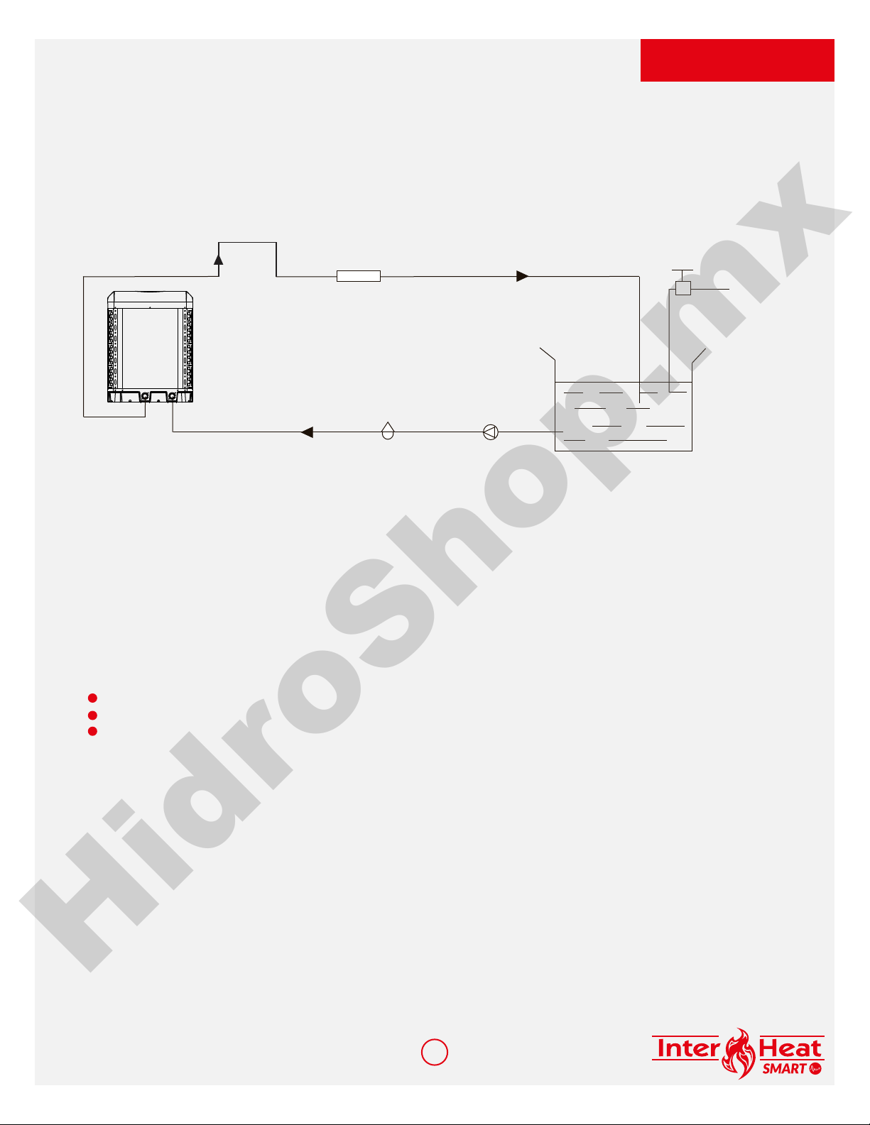
3.6 INITIAL STARTUP OF THE UNIT
NOTE- For the unit to heat the pool or spa, the filter pump must be running to circulate water
through the heat exchanger.
Start-up Procedure -After installation is completed, you should follow these steps:
Turn on your filter pump. Check for water leaks and verify flow to and from the pool.
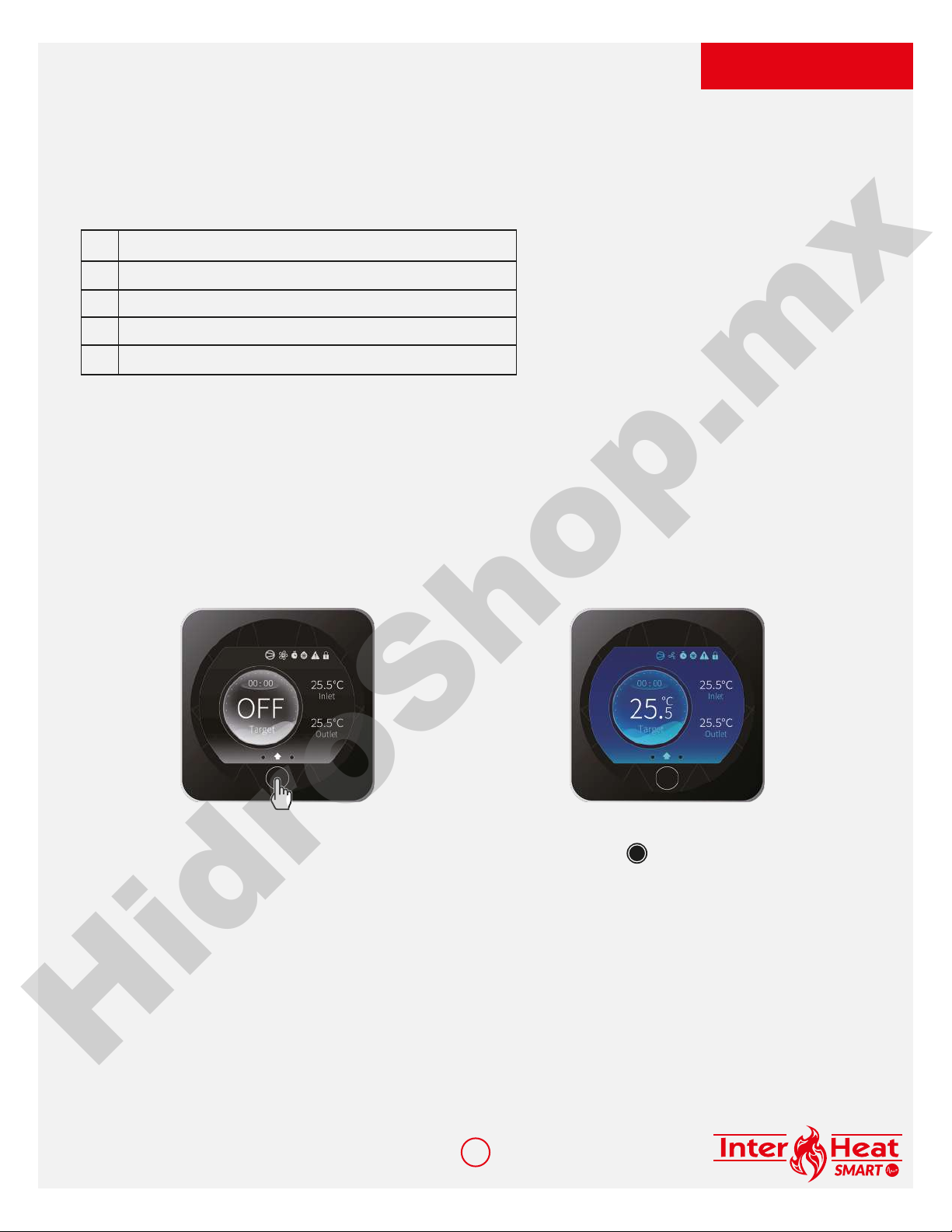
Turn on the electrical power supply to the unit, then press the key ON/OFF of the wired
controller, it should start in several seconds.
After running for a few minutes make sure the air leaving the top(side) of the unit is cooler
(Between 5-10 °C)
With the unit operating turn, the filter pump off. The unit should also turn off automatically.
Allow the unit and pool pump to run 24 hours per day until the desired pool water temperature
is reached. When the water-in temperature reaches this setting, the unit will slow down for a
period, if the temperature is maintained for 45 minutes the unit will turn off. The unit will now
automatically restart (as long as your pool pump is running) when the pool temperature drops
more than 2°C below the set temperature.
Time Delay- The unit is equipped with a 3 minute built-in solid-state restart delay included to
protect control circuit components and to eliminate restart cycling and contactor chatter. This
time delay will automatically restart the unit approximately 3 minutes after each control circuit
interruption. Even a brief power interruption will activate the solid state 3 minute restart delay
and prevent the unit from starting until the 3 minute countdown is completed.
HidroShop.mx

10
INTER HEAT SMART
115IS / 140IS
4
4.1.INTERFACE DISPLAY
OPERATION AND USE
The heat pump is equipped with a digital control panel with a touch screen, electronically
connected and pre-set at the factory in heating mode.
Legend
10
2 3 4
11
12
13
20
15
21
16
18
9875 17
19
61
14
22 2425
23
1
2
3
4
5
6
7
8
9
10
Auto mode
Cooling mode
Heating mode
Compressor’s ON indicator
Fan
Timer
Defrost mode
Alarm
Lock screen
Water Input temperature
11
12
13
14
15
16
17
18
19
20
Water Output temperature
On/Off/Back
Main screen
Setpoint temperature
System time
Operating mode selection
Adjust setpoint
Setting silence mode timer
Activate silent mode
Set On/Off timers
HidroShop.mx

11
INTER HEAT SMART
115IS / 140IS
OFF mode
When the heat pump is idle (in
standby mode), OFF is displayed as
shown on the screen.
The black screen indicates that the
heat pump is idle; settings can be
adjusted in this mode.
ON mode
When the heat pump is running
or priming (setpoint reached), the
screen turns blue.
To switch from OFF to ON mode and vice versa, press the button.
21
22
23
24
25
Access Advanced Settings
Access list of faults
Set data and time
Confirm
Back (changes not confirmed)
4OPERATION AND USE
HidroShop.mx

12
4USE AND OPERATION INSTRUCTION
INTER HEAT SMART
115IS / 140IS
6
5
71x
12
1
4
3
4.2 TIMER FUNCTION SETTINGS
The date and time can be set either in ON or in OFF mode.
Press 1 times on to return to the main screen.
HidroShop.mx

13
4USE AND OPERATION INSTRUCTION
INTER HEAT SMART
115IS / 140IS
4.3 SETTING THE ON/OFF TIMERS
2
3
5
4
1
Setting this function is necessary if you would like to run the heat pump for a shorter period
than what is defined by the filtration clock. Therefore, you can program a deferred start and an
anticipated stop or simply stop a certain timeframe from running (at night, for example).
It is possible to set one Start Timer and one Stop Timer.
The setting step is "hour to hour".
HidroShop.mx

14
4USE AND OPERATION INSTRUCTION
INTER HEAT SMART
115IS / 140IS
6
8
7
9
Press 2 times on to return to the main screen.
HidroShop.mx

15
4USE AND OPERATION INSTRUCTION
INTER HEAT SMART
115IS / 140IS
4.4 ADJUST SETPOINT
The setpoint can be changed either in ON or in OFF mode with an accuracy of 0.5°C.
1
2
3
4
51x
Press 1 times on to return to the main screen.
It is recommended to never exceed 30°C to avoid alteration of the liners.
HidroShop.mx

16
4USE AND OPERATION INSTRUCTION
INTER HEAT SMART
115IS / 140IS
4.5 MODE SELECTION
2
4
51x
3
1
Press 1 times on to return to the main screen.
HidroShop.mx

17
4USE AND OPERATION INSTRUCTION
INTER HEAT SMART
115IS / 140IS
4.6 LOCKING AND UNLOCKING THE TOUCH SCREEN
The screen can be locked or unlocked either in ON or in OFF mode.
Lock activated
Lock deactivated
5s
5s
HidroShop.mx

18
4USE AND OPERATION INSTRUCTION
INTER HEAT SMART
115IS / 140IS
4.7 SILENT FUNCTION SETTINGS
Silence mode enables the heat pump to be used in economic and very silent mode when the
heating needs are low (maintaining the pool temperature or need for ultra-silent operation).
This function can be Activated/Deactivated manually or using a Timer.
Activation/Deactivation
Silent mode deactivated
Silent mode activated
2
3
41x
1
Press 1 times on to return to the main screen.
HidroShop.mx

19
4USE AND OPERATION INSTRUCTION
INTER HEAT SMART
115IS / 140IS
Adjusting the SILENT mode Timer
2
3
1
4
5
HidroShop.mx

20
4USE AND OPERATION INSTRUCTION
INTER HEAT SMART
115IS / 140IS
6
9
10 2x
8
7
Press 2 times on to return to the main screen.
The setting step is "hour to hour".
Once the Timer is activated, it is active 7 days a week.
HidroShop.mx
This manual suits for next models
3
Table of contents
Languages:
Other Inter Water Heat Pump manuals
Popular Heat Pump manuals by other brands

Hayward
Hayward Summit Heat Pump owner's manual

Pentair
Pentair ThermalFlo 1200R H/C brochure

REMKO
REMKO ATY 266 DC Operating and installation instructions

Daikin
Daikin VRV III RXYQ5-54PY1 Service manual

EarthLinked
EarthLinked SCWD-024-1C Quick start instructions

Daikin
Daikin CHYHBH05AA installation manual

Daikin
Daikin FVXD56FV2C Service manual

System air
System air DVCompact Series Operation and maintenance instructions

STIEBEL ELTRON
STIEBEL ELTRON WPM 3 Operation and installation

Ochsner
Ochsner AIR 80 C13A Operating and installation instructions

alphainnoTec
alphainnoTec LW 140 operating manual

Amana
Amana RHA**B*A installation instructions