Interdata 8/32 User manual

Publication Number 29-526R01
MODEL
8/32
(~USTOMER
INSTALLATION MANUAL
Subsidiary
of
PERKIN-ELMER
Oceanport,
New
Jersey
07757,
U.S.A.
@
INTER
DATA
INC.,
1976
All
Rights Reserved
Printed
in
U.S.A.
September
1976
PAGE
1-
8
9
10-11
12
13-26
PAGE
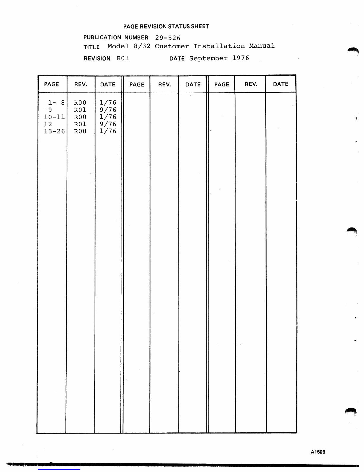
REVISION STATUS
SHEET
PUBLICATION
NUMBER
29-526
TITLE
Model
8/32
Customer
Installation
Manual
REVISION
RO
1 DATE
September
1976
REV.
DATE
PAGE
REV.
DATE
PAGE
REV.
DATE
ROO
1/76
ROI
9/76
ROO
1/76
ROI
9/76
ROO
1/76
,
A1698
'.i
..
q~,
..
,
...
~""·
.......................................................................
1
....
.
..
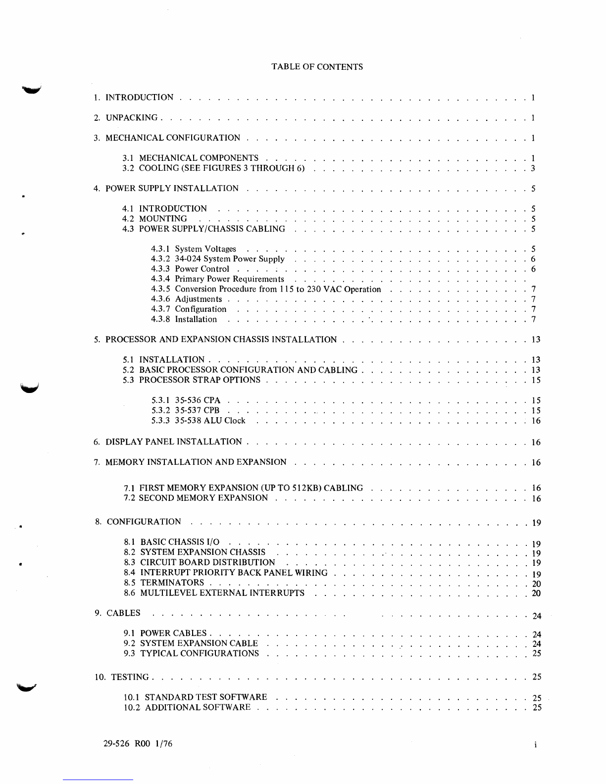
TABLE
OF
CONTENTS
1.
INTRODUCTION
2.
UNPACKING
..
3. MECHANICAL
CONFIGURATION
3.1 MECHANICAL COMPONENTS
3.2
COOLING
(SEE
FIGURES
3
THROUGH
6)
4. POWER SUPPLY
INSTALLATION
4.1
INTRODUCTION
4.2
MOUNTING
4.3 POWER SUPPLY/CHASSIS CABLING
4.3.1
System
Voltages . . . . .
4.3.2
34-024
System
Power
Supply
4.3.3
Power
Control
. . . . . .
4.3.4
Primary
Power
Requirements
4.3.5
Conversion
Procedure
from 115
to
230
VAC
Operation
4.3.6
Adjustments
.
4.3.7
Configuration . . . . . . . . . . .
4.3.8
Installation
. . . . . . . . . . . .
5.
PROCESSOR
AND EXPANSION CHASSIS
INSTALLATION
5.1
INSTALLATION
.............
.
5.2 BASIC
PROCESSOR
CONFIGURATION
AND
CABLING.
5.3
PROCESSOR
STRAP
OPTIONS
5.3.1
35-536
CPA . . .
5.3.2
35-537
CPB . . .
5.3.3
35-538
ALU
Clock
6. DISPLAY
PANEL
INSTALLATION
.
7.
MEMORY
INSTALLATION
AND
EXPANSION
7.1
FIRST
MEMORY EXPANSION (UP
TO
512KB)
CABLING
7.2 SECOND MEMORY EXPANSION
8.
CONFIGURATION
....
8.1 BASIC CHASSIS
I/O
8.2
SYSTEM EXPANSION CHASSIS
8.3
CIRCUIT
BOARD
DISTRIBUTION
8.4
INTERRUPT
PRIORITY
BACK
PANEL
WIRING
8.5
TERMINATORS
..........
.
8.6
MULTILEVEL
EXTERNAL
INTERRUPTS
9. CABLES
9.1 POWER
CABLES.
9.2
SYSTEM EXPANSION CABLE
9.3
TYPICAL
CONFIGURATIONS
10.
TESTING.
. . . . . . .
....
10.1
STANDARD
TEST
SOFTWARE
10.2
ADDITIONAL
SOFTWARE
..
29-526
ROO
1/76
1
3
5
5
5
5
5
. 6
6
7
7
7
7
13
13
13
15
15
15
16
16
16
16
16
19
19
19
19
19
. 20
. 20
24
24
24
25
25
25
25

Figure
1.
Figure
2.
Figure 3.
Figure 4.
Figure
5.
Figure 6.
Figure
7.
Figure
8.
Figure 9.
Figure 10.
Figure 11. .
Figure 12.
Figure 13.
Figure 14.
Figure 15.
Figure 16.
Figure 17.
Figure 18.
Figure 19.
Figure 20.
Figure 21.
Figure 22.
Figure 23.
Figure 24.
Figure 25.
TABLE
1.
ii
FIGURES
System Cabinet Physical Dimensions . . . . . .
Typical Mounting Configuration for Display and Filler Panels
Enclosure
Front
View.
. .
Enclosure Section View A-A .
Blank Cover (Solid)
. Duct
Outlet
Cover (Perforated)
Wiring
of
the
Blower Air Switch
34-024 Power Supply Mounting
Power Control Circuit Diagram
Wiring
of
the
Second
Deck
of
the Rotary Switch
for Control
of
Different AC
Phases.
. . . . .
Basic
8/32
with 128KB Memory Power Distribution
Model
8/32
with 256KB Memory Power Distribution
Model
8/32
with 384KB and 512KB Memory Power Distribution
Model
8/32
Power Wiring for 640KB
to
1024KB Power Distribution
Model
8/32
Basic with Double Floating Unit
and/or
Writable Control Store Power Distribution
16-398 Half Board
Adapter.
.
02-234 I/O Adapter (Top View)
Basic Processor;
Front
View
.Basic Processor; Rear
View.
.
Front
View
of
Processor Configuration with First Memory Expansion
Front
View
of
Processor Configuration with First and Second Memory Expansion
Standard
Interrupt
Priority.
. . . . . .
Modified
Interrupt
Priority.
. . . . . .
Interrupt
Priority with ESELCH Installed .
Typical System Configuration (Back Panel)
TABLES
2
3
4
4
4
4
4
5
6
6
8
9
10
11
12
14
14
15
17
17
18
21
22
23
26
PROCESSOR CABLES . . . . . . . . . . . . . . . . . . . . . . . . . 15
29-526
ROO
1/76
~,
~
~I
·~id""""""""""""""""""""""""""""""""""""""""""""""
................
.
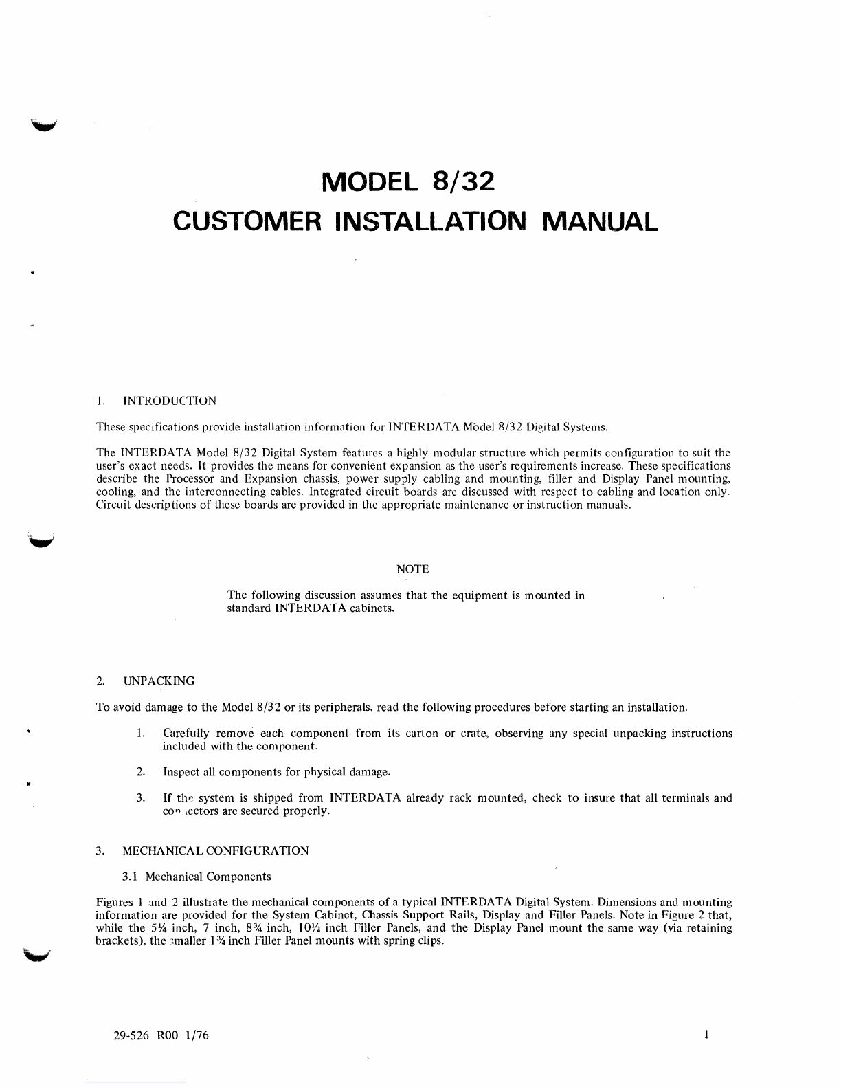
MODEL
8/32
CUSTOMER INSTALLATION MANUAL
1.
INTRODUCTION
These specifications provide installation information for INTERDATA Mbde18/32 Digital Systems.
The INTERDATA Model
8/32
Digital System features a highly modular structure which permits configuration
to
suit the
user's exact needs.
It
provides the means for convenient expansion
as
the
user's requirements increase. These specifications
describe the Processor and Expansion chassis, power supply cabling and mounting, filler and Display Panel mounting,
cooling, and the interconnecting cables. Integrated circuit boards are discussed with respect
to
cabling and location only.
Circuit descriptions
of
these boards are provided in the appropriate maintenance
or
instruction manuals.
NOTE
The following discussion assumes
that
the
equipment
is
mounted
in
standard INTERDATA cabinets.
2.
UNPACKING
To avoid damage
to
the
Model
8/32
or
its peripherals, read
the
following procedures before starting an installation.
1.
Carefully remove each
component
from its carton or crate, observing any special unpacking instructions
included with
the
component.
2.
Inspect all components for physical damage.
3.
If
thf~
system
is
shipped from INTERDATA already rack
mounted,
check
to
insure
that
all terminals and
co'" ,ectors are secured properly.
3. MECHANICAL CONFIGURATION
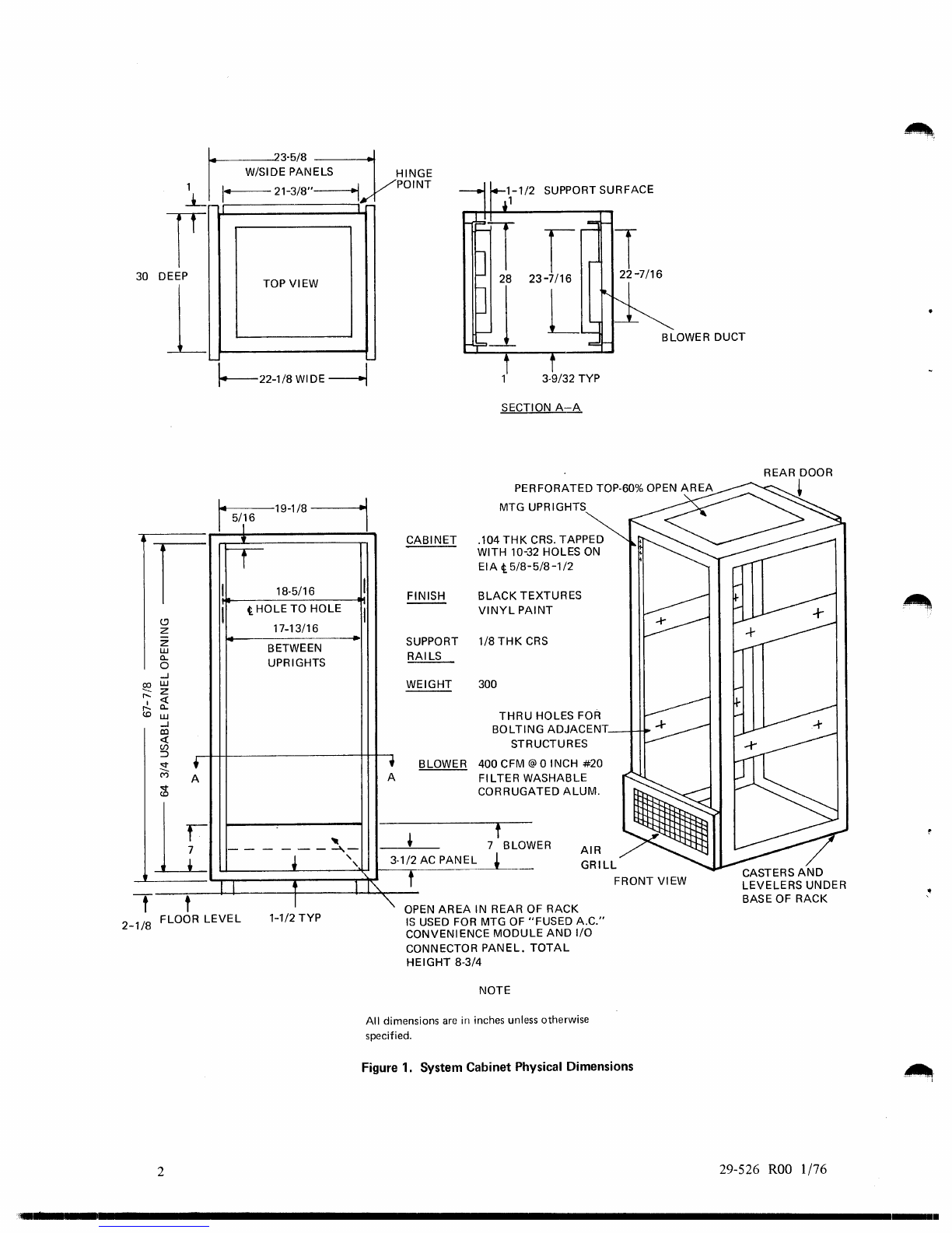
3.1 Mechanical Components
Figures 1 and 2 illustrate
the
mechanical components
of
a typical INTERDATA Digital System. Dimensions and mounting
information are provided for
the
System Cabinet, Chassis
Support
Rails, Display and Filler Panels. Note in Figure 2
that,
while
the
5Y4
inch, 7 inch, 8% inch,
lOY2
inch Filler Panels,
and
the
Display Panel
mount
the
same way (via retaining
brackets),
the
:~maller
134 inch Filler Panel
mounts
with spring clips.
29-526
ROO
1/76
~:.;~8N~
HINGE
1 I
1-=-21-3/8"---IYPOINT
t-
I
SUPPORT SURFACE
30 DEEP TOP VIEW
1 BLOWER DUCT
I
c.!)
z
Z
UJ
a..
0
...J
~
UJ
z
r-..
«
I
r-..
a..
(0
UJ
...J
co
«
(/)
:::>
~
+
M A
<::t
(0
1I
t t
'-
\'---22-1/8
WIDE
~
~19-1/8
----l
I
5/
1
16 I
•
rr
I 18·5/16 I
I t HOLE TO HOLE I
17-13/16
-BETWEEN
UPRIGHTS
--
--
-- -
--"1.-
• ,
,
I t I I'\.
I
CABINET
FINISH
--
SUPPORT
RAILS
WEIGHT
, BLOWER
A
~
3·1/2 AC PANEL
t
3·9/32 TYP
SECTION
A-A
PERFORATED TOP·60% OPEN
AREA
MTG UPRIGHTS
.104
THK
CRS.
TAPPED
2 HOLES
ON
WITH 10-3
EIA
t
5/8-
5/8-1/2
BLACK
TEXTURES
NT
VINYL
PAl
1/8
THK
C
RS
300
THRU
BOLTINHOLES FOR
G ADJACENT
UCTURESSTR
400 CFM @ oINCH
#20
ASHABLE
TED
ALUM.
FILTERW
CORRUGA
f
7 BLOW
~
ER
AIR
GRILL
FRONT VIEW
"
OPEN
AREA
IN REAR OF RACK
2-1/8
FLOOR
LEVEL
1-1/2
TYP
IS
USED FOR MTG
OF
"FUSED
A.C."
CONVENIENCE MODULE
AND
I/O
2
CONNECTOR
PANEL.
TOTAL
HEIGHT
8·3/4
NOTE
All
dimensions are
in
inches unless otherwise
specified.
Figure 1. System Cabinet Physical Dimensions
29-526
ROO
1
/76
..
'
...........................................................................................................
1
.....
.

FILLER
PANELS
&
DISPLAY
PANEL
RIGHT
~
CHASSIS SUPPORT
RAIL
~
~
~
~-tt[
~
18.5/16· METHOD USED TO
MOUNT
I
~'3/4"FILLERPANEL
o BOLTS
TO
RACK UPRIGHT
NOTE
I
I
?~a
<\
\
RETAINING
BRACKET
(21
\ NO. 10SPLIT LOCK. {4)
NO. 10·32 x 3/BLG
PHPS
14)
All
dimensions
are
in inches.
Figure
2.
Typical Mounting Configuration
for
Display
and
Filler
Panels
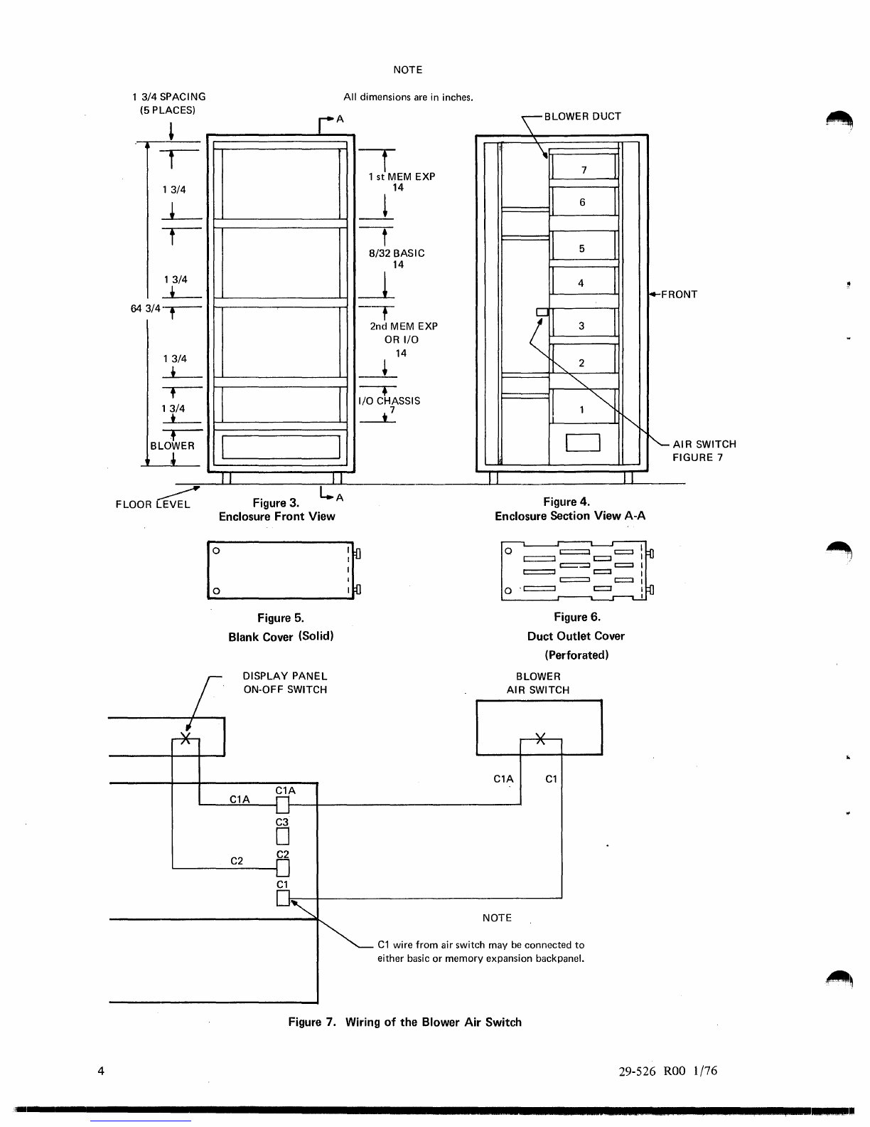
3.2 Cooling (See Figures 3 through 6.)
Cooling
is
accomplished by forced air at ambient room temperature, via a packaged blower located at the bottom
of
the
cabine:t (Figure 3). Distribution
of
air
is
accomplished by an internal plenum which
is
located along the right side
of
the
cabinet opening (as viewed from the front). The air outlet from the blower enters directly into the bottom section
of
the
plenum (Figure 4). The plenum contains seven removable covers located vertically in the appropriate spaces
as
illustrated
by Figure 4.
The blower must be plugged into the
AC
panel at the rear
of
the cabinet, and the main circuit breaker on the
AC
panel
must be in the
ON
position to power up the system.
The blower air switch located on the side
of
the plenum system (Figure 4)
is
wired per Figure
7.
It
is
recommended that the blower remain on for a minimum
of
five
minutes after the Display Panel's LOCK-aN-OFF
switch
is
turned to the OFF position.
The blower
is
shut
off
by the main circuit breaker on the
AC
power panel.
A removable and washable filter
is
located behind the air int
••
!:-=:
g,.~~!:.,.
Two types
of
covers are provided, solid and perforated (see Figures 5 and 6). Solid
.covers
are snapped in place at locations
where there are no card files. Perforated covers are used in locations having an operating card
file.
For
the
Basic Model
8/32
with no expansion, perforated covers are installed at Locations 4 and
5,
and solid covers are
installed in all other locations. If, at a later date, the first memory expansion
is
added, the solid covers at Locations 6 and 7
are replaced with perforated covers.
Two variations
of
blowers are available: 115VAC 50/60
Hz
(36-025FOI) and 220VAC 50
Hz
(36·025F02).
29-526
ROO
1/76 3
4
1
3/4
SPACING
(5
PLACES)
13
/4
13
/4
-L-
64
3/4--r--
13
/4
-L-
,--
/4
13
-*--
,-
BLOW
ER
,
FLOOR~
I
J
rA
I
J I
L..A
Figure
3.
Enclosure Front View
Figure
5.
Blank Cover (Solid)
DISPLAY
PANEL
ON-OFF SWITCH
C1A
C1A
C3
o
C2
C2
C1
NOTE
All
dimensions
are
in inches. \ BLOWER DUCT
"-
f
It
7 I
1
st
MEM EXP
14
-!
II
6 I
-t
I
II
5
8/32
BASIC
14
~
I 4 I
-T
(
II
I
2nd MEM EXP 3
OR
I/O
14 l I
-+
2
"'"
-.
II
1"i
I/O
CHASSIS
~
'"
"-
D
II
II
Figure 4.
Enclosure Section View
A-A
o
c::=::::l
c::::J
c:=::::J
c::::J
r:::::=::::I
c::::J
t::::=:=l
c:=:J
c:::::::=:J c::::::l
o .c:=:::::::J
c::::J
Figure 6.
Duct Outlet Cover
(Perforated)
BLOWER
AIR
SWITCH
C1A
C1
NOTE
C1
wire
from
air switch may
be
connected
to
either basic or memory expansion backpanel.
i4-FRO
'-AI
FI
NT
R SWITCH
GURE 7
Figure
7.
Wiring
of
the Blower
Air
Switch
29-526
ROO
1/76
'-
............................................................................................
~
..
I
.....
.

4. POWER SUPPLY INSTALLATION
4.1 Introduction
This section describes the installation
of
the Model
8/32
Power Supply. Mounting information and cabling instructions are
provided for the 34-024 Power Supply in various configurations.
4.2 Mounting
The power supplies mount directly behind the Processor and Expansion chassis (see Figure 8). They are attached
to
the
right mounting upright (viewed from the rear). There
is
adequate slack in the power supply cable
to
allow the power
supply
to
swing out. To prevent the cable from being pinched between the power supply and chassis support rails, a service
loop
is
required.
WARNING
BEFORE SWINGING OUT THE POWER SUPPLIES, THE RACK
LEVELING FEET SHOULD
BE
LOWERED. UP TO FIVE POWER
SUPPLIES CAN
BE
SWUNG
OUT AT ONE TIME AFTER THE
LEVELERS ARE IN CONTACT
WITH
THE FLOOR SURFACE.
The power supplies may be swung in
or
out
on their mounting pivots for easy access
to
the back plane. When they are in
operating position, they are secured by two 10-32 screws which attach
to
the left mounting upright (viewed from the rear).
NO. 10-32X 1/2
P.H.
NO.
10 SPLIT LOCK
NO.
10
FLAT
WASHER
NO.
10·32X 1/2
P.
H.
NO.
10
SPLIT LOCK
o
o
o
Figure
8.
34-024 Power Supply Mounting
4.3 Power Supply/Chassis Cabling
4.3.1 System Voltages. The Model 8/32 System requires three system voltages:
Mnemonic
P5
PIS
PIS
Any other voltages locally generated are
not
considered system voltages.
29-526
ROO
1/76
+5V
+16.5V
-I6.5V
5
4.3.2 34-024 System Power Supply. This standard INTERDATA Power Supply
is
used for all power require-
ments in the Model
8/32
System. All three outputs (P5, N15, and
PIS)
are short circuit protected, and regulated
to
±I%
when normally loaded.
PIS
and N15 are oveIVoltage protected.
Refer
to
Switching Regulated Power Supply Manual, Publication Number 29-397 for installation and operating details.
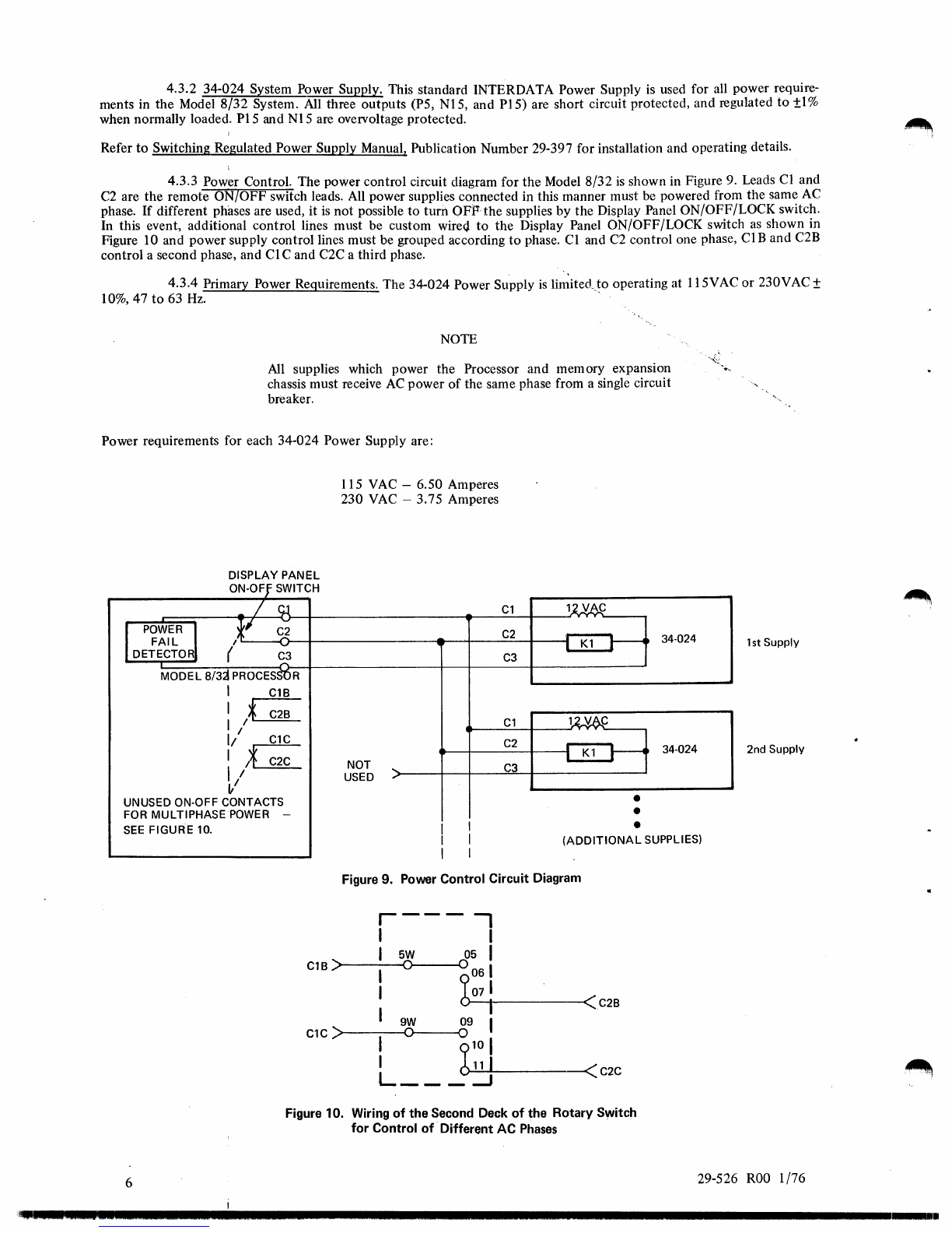
4.3.3 Power Control. The power control circuit diagram for
the
Model
8/32
is
shown in Figure 9. Leads Cl and
C2
are the remote ON/OFF switch leads. All power supplies connected in this manner must be powered from the same
AC
phase. If different phases are used, it
is
not possible
to
turn OFP-the supplies by the Display Panel ON/OFF/LOCK switch.
In this event, additional control lines must be custom wire(j
to
the Display Panel ON/OFF/LOCK switch
as
shown in
Figure 10 and power supply control lines must be grouped according
to
phase. CI and
C2
control one phase,
CIB
and C2B
control a second phase, and
Cl
C and C2C a third phase.
4.3.4 Primary Power Requirements. The 34-024 Power Supply
is
li~itedJo
operating at 115VAC
or
230V
AC
±
10%,47
to
63
Hz.
.
NOTE
All
supplies which power the Processor and memory expansion
chassis must receive
AC
power
of
the same phase from a single circuit
breaker.
Power requirements for each 34-024 Power Supply are:
DISPLAY PANEL
ON-OFf
SWITCH
-/
,U
I
POWER,J
FAIL
DETECTO (
C3
.....
MODEL
8/3j
PROCESS'OR
I C18
I *C28
I /
1/
C1C
:
/~
C2C
~/
UNUSED ON-OFF CONTACTS
FOR MULTIPHASEPOWER -
SEE
FIGURE 10.
115 VAC -6.50 Amperes
230
VAC
-3.75 Amperes
NOT
....
USED "
I I
Cl
11vAj:
.-
C2
I
Kl
~
34·024
C3
lU6..C
Cl
.-
C2
;
Kl
~
34-024
C3
•
•
•
1st
Supply
2nd
Supply
I I
(ADDITIONAL
SUPPLIES)
6
I I
Figure 9. Power Control Circuit Diagram
r---
-,
I I
I
5W
05 I
C18
)>------<0
0
I
b0
61
I
071
-11------<C28
I
9W
09 I
Cl
C
)>-----<0
0
I
910
I
I
O..:...11~1L-
___
--«
C2C
L
___
~
Figure 10. Wiring
of
the Second Deck
of
the Rotary Switch
for
Control
of
-Different AC
Phases
29-526
ROO
1/76
'~I._
.5
.....
'.'.22.'
•••
2
.....................................................................................................
.
4.3.5 Conversion Procedure from 115
to
230 VAC Operation. The 34-024 Power Supply
is
shipped from the
factory strapped for 115 VAC.
To
switch
to
230 VAC operation, use
the
following procedure prior
to
mounting
the
Power
Supply in the rack.
1.
Remove
the
four screws and swing
the
hinged
top
and back panel open
to
expose Terminal Board 1
(TBl)
on
the
front panel. (See Functional Schematic 34-024D08 in
the
Switching Regulated Power Supply Manual,
Publication Number 29-397, for details.)
2.
Ascertain
that
the
TBl~erminals
are strapped
as
indicated for 115 VAC operation.
1
to
2 3
to
4 5
to
6 8
to
9
3. Remove all four straps.
4. For 230 VAC operation, add the four straps
to
the
following TBI terminals:
2
to
3 (use
two
straps) and 4
to
5 (use two straps)
NOTE
Two straps are used for each connection
to
keep four straps available
to
convert back
to
115 VAC operation,
if
required.
5.
Reassemble
the
power supply by swinging
the
hinged
top
and back panel
into
place and replace
the
four
screws.
4.3.6
Adjustments. Ali power system adjustments are made at
the
factory and should not require readjustment
in
the
Held.
If
readjustment becomes necessary,
the
recommended settings are given below.
Voltage Adjustments:
Mnemonic
P5
PIS
N15
Voltage Setting
+
5.1
Volts
+16.5 Volts
-16.5
Volts
Voltages should always be measured
at
the
backpanel when making adjustments. These adjustments are made
after
disconnecting the tracking thermistors and placing a 1 K
ohm
:±5%
resistor across the thermistor terminals.
~::::rowbar
Adjustments (Overvoltage):
Output
Voltage
PIS
N15
Firing Voltage Adjustment
19.5 Volts
19.5 Volts
All firing
voltag~s
are measured at the back panel when making adjustments. These voltage adjusting potentiometers are
accessed
by
removing
the
front panel
of
the power supply.
4.3.7 Configuration. In a Model
8/32
System, the minimum system configuration consists
of
one twin chassis
and
two
standard INTERDATA 34-024 Power Supplies (Product Number M49-026). Figure
11
shows the
power
distribu-
tion
of
the basic system.
4.3.8 Installation. The installations for the various power systems are:
1.
Connect
the
cables
to
the twin chassis; referring
to
one
of
the following figures, depending upon the configur-
ation:
-Basic
8/32
Processor with 128KB Memory (Figure 11).
-Basic
8/32
Processor and First Memory Expansion Chassis with 256KB Memory (Figure 12).
-Basic
8/32
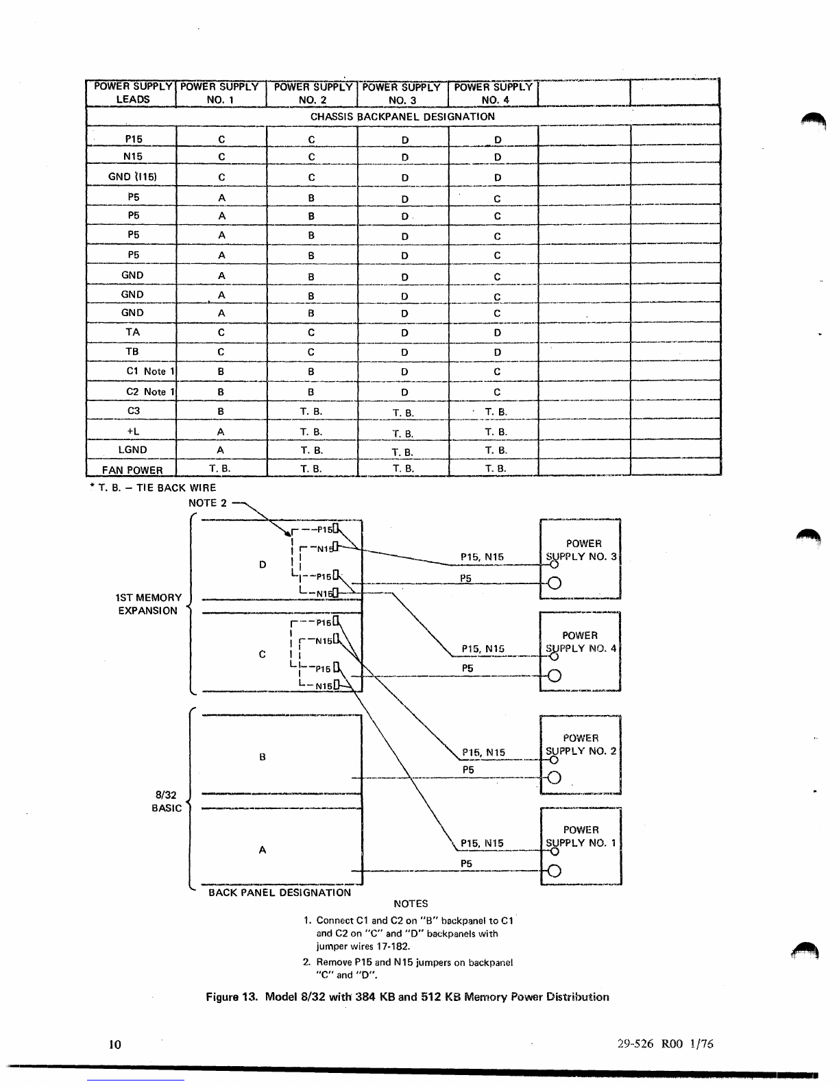
Processor and First Memory Expansion Chassis with 384KB and 512KB Memory (Figure 13).
-Basic
8/32
Processor, First and Second Memory Expansion
Ch3<;sis
with 640KB
to
1024KB Memory (Figure 14).
-Basic
8/32
Processor with Double Floating Unit
ar.~.'::)T
,l/rita:"';", Culli.rol Store (Figure 15).
Note
that
the
memory expansion backpanel contains
two
sets
of
+15 and -15 VDC power busses, and in some
configurations it
is
necessary
to
connect
the
busses with
jumper
cables.
2.
Cables from
the
front
of
the
chassis may be
routed
through the 1%inch space between chassis (see Figure 3).
If
there are any unused connectors, secure them
to
prevent shorting.
29-526
ROO
1/76 7

POWER
SUPPLY
POWER
SUPPLY
POWER
SUPPLY
LEADS
NO.1
NO.2
CHASSIS BACK
PANEL
DESIGNATION
P15
B B
N15 B B
(4)
P5
A B
(3) GND A B
GND (+15) B B
TA
A B
TB A B
C1
B B
C2
B B
C3
B T.
B.
+L
A T.
B.
LGND A T.
B.
FAN
POWER
*T.
B.
T.
B.
~,
T.
B.
-TIE BACK WIRE
8
8/32
BASIC
B
P5
P5
P5
P15.N15
P5
~-+
_____________
P_5
________
--H
A
P5
P5
P5
BACK
PANEL
DESIGNATION
P15. N15
P5
POWER
SUPPLY
NO.2
POWER
SUPPLY
NO.1
Figure 11.
Basic
8/32
with
128 KB Memory Power Distribution
29-526
ROO
1/76
--------------------
....................................................................
--
...................
.

~
POWER SUPPLY
POWE
R SUPPLY POWER SUPPLY OWER SUPPLY I ]
LI:ADS
NO.1
NO.2 NO.3
~.
CHASSIS
BACKPANEL
DESIGNATION
P15
T.
B.
C
I)
"
--'
-
iN~5
T.
B.
C D
.-
---
GNp
(115) T.
B.
C D
._-
P5
A B C
P5
A B
c:;
P5
A B D
P5
A B
()
_.
GND
A B G
_.
--
_.
GND
A B
()
--f---'
GND
A B D
TA
T.
B.
Note
2 C D
T.B. T.
B.
Note 2 C D
---
C1
Note 1 B B
[)
-
C2 Note 1 B B
[)
C3 B T.
B.
T.
B.
+L
A T.
B.
T.
B.
-..
-._
.
.....
_.
_.
L.GND A T.
B.
T.
B.
-
FAN
POWER T. B. T.
B.
T.
B.
-.
* T.
13.
-
TIE
BACK
WIRE
,.
-]
POWER
D P16,
N15
SUPPLY
NO.3
-
1.--.
--
I---.-.=t-.
1st
MEMORY.
EXPANSION
C -
~_-.-i.~,
N15
\",'
,.
roWE:]
B
SUPPLY_No.2
-
-'---
P5
8/3~
oC
BASIC
A
______
P....;;5:.......
_____
..+{
'"
BACK
PANEL
DESIGNATION
29-5i26
ROl
9/76
NOTES
1.
Connect
eland
C2
01'1
"B"
backpanol
to
C1and
C2
on
"D"
backpanels
with
jumper wires 17-18'2.
. \
2. P15 and N16 voltages
on
this Power Supply
must
be
adjusted
to
within
a range
of
15
to
17.5 volts
to
prevent crowbars
from
triggering.
Figure 12. Model 8/32 with 256
KB
Memory Power Distribution
......
TIE
BACK
I
9
POWER
SUPPLY
POWER
SUPPLY
POWER
SUPPLY
POWER
SUPPLY
POWER
SUPPLYr'···-'~-"-'I~------'-·
LEADS
NO.1
NO.2
NO.3
NO. 4
1~--~-~-
___
_
CHASSIS PACKPANEL DESIGNATION
~_----~~
__
~
_____
~--
__
--~
__
--C------+_----D------;_-----.---D
____
+-_
P15
C
------~-.------,-----
I---------I--_--=
____
-I-
___
_=C
_______
-.-.----~---
r---'-~--
------
..
-----1----------
N15 C
.-1---------
C D D
---+--------
,-.----.------r-----------I-------.-
GND 1I15) C
P5
A
__
--I~---B----I_-----D-
_
___4_-,----=C---_+----.-
..
---f--.--.-----
P5
A B
O.
C
----+-.---------~--,,----------+----------I----------I--.---~---
P5
A B 0 C
I------------I-----------,--~-----------,-~.----------+-----------~----------
+---------
P5
A
__
,_-+-
_____
-+
____
B
______
r-
____
.?
_______
C
__
.
____________
-4-
________
_
GND A
______
I--
___
B
____
I--_~
___
~____
_
____
•
___
C
__________
.
____
1-
_____
_
________
-I--
__
>-
____
-+
_____
B
______
f--
_____
D
_____________
f
___
.
__
I----.--------f-'
--
GND A
GND A B 0 C
......
,-----~------+-------+-------.----
._------.-------
-------.~--.--~--------
TA
C C o 0
I---------I---------,-t---
------+-------.--
--+
...
--------t----------~-+---.----
TB C
COD
,-----------+--------+-,-.-----
_._----+----------1--------..---1--._-_._---
C1
Note 1 B B 0 C
---
-------------
1--.-_._-------
,---------,-1---.-
C2
Note 1 B B 0 C
J------~------+_--------.
f---------!---.----.--!---------------
.-------
,
____
----4-
______
-+-
___
T
_._
B
_.
__
-+-.
____
T
_._
...
B
:....
_____
t-
___
._..:.._._!~.-~:...-----I---.-"--,---I--------
..
--
C3
B
T.
B.
T.B.
T.
B.
_____
~----------f__----_-
__
--~
+L
A
1-,
LGND A
_._~-----_t_---T-.
_B_.
____
f-
___
-I
.
.l!:
____
I-
___
T
_.
_B_"
---11-.-----.--4----.---
FAN
POWER
T.
B.
T.
B.
T.
B.
T.
B.
* T.
B.
-
TIE
BACK WIRE
1ST MEMORY
EXPANSION
10
8/32
BASIC
D
c
B
A
=fi
----
'--J
POWER
~
SJPPLYNO.3
____ .
P5
_
~
~
GE~J
----
~~:=£:J
~~-.
P5
~15.
1\115
P5
BACK PANEL DESIGNATION NOTES
1.
Connect
C1
and
C2
on
"B"
backpanel
to
C1'
and
C2
on
"c"
and
"0"
backpanels
with
jumper wires 17-182.
2.
Remove P15 and N15 jumpers
on
backpanel
"e"
and
"0".
Figure 13. Model
8/32
with'
384
KB and 512
KB
Memory
Power
Distribution
29··526
ROO
1/76
'--------------------------------------
.........................................
.

POWER
SUPPLY
POWER
SUPPLY
pOWE
R SUPPLY
POWER
SUPPLY
POWER
SUPPLY
LEADS
NO.1
NO.2
NO.3
NO.4
_.
CHASSIS
BACK
PANEL DESIGNATION
-'P15
F C D E
_.
.-.~
N15 F C D E
GND (+15) F C D E
_.
-
P5
A B D E
_.
----
P5
A B D E
_.
P5
A B C F
-.
P5
A B C F
-.
GND A B D E
-.
--
GND A B C F
_. -.
GND A B C F
_.
--
TA
F C D E
_.
TB F C D E
_.
--
C1
B B D E
_.
-
C2
B B D E
_.
---'---"--
-.
C3
B T.
B.
T.
B.
T.B.
--
--
+L
A T.
B.
T.
B.
T.B.
--
LGND A T.
B.
~..J"~_
T.B.
--
--
FAN
POWER
*T.
B.
T.
B.
T.
B.
·T.B.
*T.B. -
TIE
BACK WIRE
1st MEMORY
EXP,llINSION
8/32
BASIC
2nd MEMORY
EXPANSION
29-526
ROO
1/76
POWER'-j
_
____________________
~+---------.-.-----~-~~~~-~-~-~-~----------~~-SuUPPLYNO_.
3
D P15 N15
P5
'
"
C -
;-._---
B
P15,N15
P5
A
P15,N15
P~
--
F
E P15, N15
P5
BACK PANEL DESIGNATION NOTE
Connect
Cl
and
C2
on
"8"
backpanel
to
Cl
and
ci
on
"0"
and
"E"
backpanels
with
jumper wires 17·372.
SUPPLY
NO.2
POWER
1
0
J
POWER
SUPPLY
NO.1
-0
POWER
SUPPLY
NO.4
Figure 14. Model 8/32 Power Wiring
for
640KB
to
1024KB Power Distribution
11

I
POWER SUPPLY
LEADS
POWER
SUPPLY
POWER
~~P;~1PO~ER-~~;PL~-r;~WER
SUPPLY
NO.1
NO.2
NO.3
In.
NO.4
CHASSIS BACKPANEL DESIGNATION
POWER
SUPPLY
NO.5
---G-N~~
,:>-)---1---.--_-
__
4-
1.
_.-_-_~~-~-___
~.-----._----+
-_
-_
-_-
_-_-_~~-_--_-_+_--....:
T.~..:...:-=
":::....:
--.------1
______
P_5
_______
+-
____________
~-------~.--------~--~-------------4_----~A~--~r_-----------1
____
P_5
____
-
____
.
__
._f-.
___
.
___
-+
______
.
___
t-
________
-I-
___
-.!'..A~
____
+_-----_;
P5
=1=----
A
-----~-
----------4-------.------------------.--~---------_;------~A~---_r_----------_1
__
G~
___________
__+------------
__________
.
______
-+-
__
~A~
__
+_-----;
GND A
..
__
---'G'-'-N~D
r--.--------
r----------+----------+----------+----~A:..-.--___if__--------1
____
I~
..
__
.
__
1'"'--'
.
~------.-.-
..
-_+,_------+-_--T:...:.-=B:..:..;.:N:.;;:o.:;te;,...l-+------.----t
TB 1
__
.
_________
41
__________
-+
___
T~.~B~.N~0~te~1-----
__
----,
---~~----
-------
~-----==T
____
...
I B
----------
-+
-.--
..
--~.---------+_--------_lf_--------;
-~--
f--.
--+-----
_____
.
___
r-
___
.
_____
--1
______
B
___
t-
_______
-t
;--'--:~'---g--
----~---i=----
--'
-+-.----+-~-:
::--t----;
LGND
__
__._
_.-lI
_______
+-
_____
-+-
__
T~
.
.....;B:..;,.
__
+__---
_
_1
~.POWER
__
I
.-li
____________
~
__________
~
____
T~.~B~.
____
~
__________
_
* T.B. -
TIE
BACK WIRE
12
8/32
BASIC
B
NOTE 2
POWER
SUPPLY
NO.2
_____
.
P15,
NJ~5:"----f-_{)
P5
-
--1
POWER SUPPLY
NO.1
P15,N15
-<)
P5
-1
BACK
PANEL
DESIGNATION I
POWER
SUPPLY
NO.5
I
'---
______
P~5
______
~~~
NOTES
1.
P15 and N15 voltages
on
this Power Supply
must be adjusted
to
within a range
of
15
to
17.5 volts
to
prevent crowbars from triggering.
2.
Remove P5 jumper
on
backpanel
"A".
Figure 15. Model
8/32
Basic
with
Double Floating
Unit
and/or Writable
Control
Store Power
Distribution
29-526
ROI
9/76
----------------------------------------------------------------------------
____
.0
.....
5.
PROCESSOR AND EXPANSION CHASSIS INSTALLATION
5.1
Installation
For
different memory expansions,
it
is
possible
to
have from one
to
three twin chassis in the Mode18/32 System (located
as
shown in Figure 3). Figures
II
through
15
show the three possible configurations.
Prior
to
mounting the chassis, replace the appropriate solid covers on
the
plenums with perforated covers (see Section 3.2).
The 8/.32 Basic System and its memory expansions must always be mounted in a cabinet
that
is
equipped with a blower
and plenum.
It
must be configured
as
shown in Figure
3.
These chassis do
not
have chassis fans. (Seven inch and 14 inch
chassis with fans are
not
to
be used.) When 7 inch I/O chassis without fans are
to
be mounted in this cabinet,
they
must be
installed in positions where duct covers are located (see Figure 3).
CAUTION
IF
A CABINET OTHER THAN
AN
09-069 INTERDATA CABINET
IS USED, THE USER MUST SUPPLY HIS
OWN
FORCED AIR
COOLING SYSTEM.
To
mount
a chassis, slide the chassis into the rack on the chassis support rails from the front
of
the rack (see Figures I and
2). CAUTION
NO
CHASSIS SHOULD BE MOUNTED
IN
CANTILEVER
FASHION. CHASSIS SUPPORT RAILS MUST
BE
USED. IF A
RACK CABINET OTHER THAN AN INTERDATA
IS
USED,
CONSULT THE RACK MANUFACfURER FOR PROPER
SUPPORT RAILS.
The chassis support rails are fastened
to
the mounting uprights
of
the front and rear
of
the rack. The Expansion and
Processor chassis are screwed in place at the mounting uprights in front
of
the rack.
5.2 Basic Processor Configuration and Cabling
The basic Model
8/32
with 128KB
of
memory
is
comprised of:
1.
4 each 32-198 32KB core modules
2.
2 each 35-534
LMI
3.
1 each 35-535
MBC
4. I each 35-536 CPA
5.
I each 35-537
CPB
6.
1 each 35-555
CPC
7.
1 each 35-538 ALU
8.
1 each 35-539 IOU
Upper Slots 2, 4,
5,
and 7
Upper Slots 3 and 6
Upper Slot 1
Upper Slot a
Lower Slot 7
Lower Slot 6
Lower Slot 4
Lower Slot 3
Lower Slot 5
is
reserved for the optional Double/Precision Floating-Point Unit (DFU). Lower Slots 0,
1,
and 2 are reserved
for I/O. Either full or halfboard I/O may be plugged
into
these slots. One or two 7 inch halfboards may be inserted
into
the
15
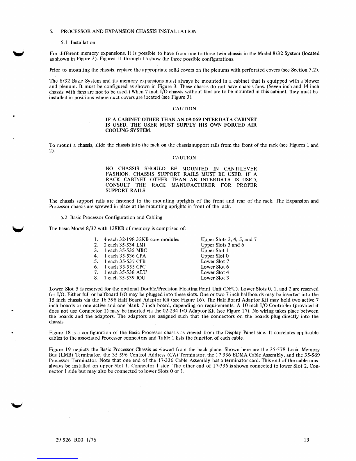
inch chassis via the 16-398 Half Board Adaptor Kit (see Figure 16). The HalfBoard Adaptor Kit may hold two active 7
inch boards
or
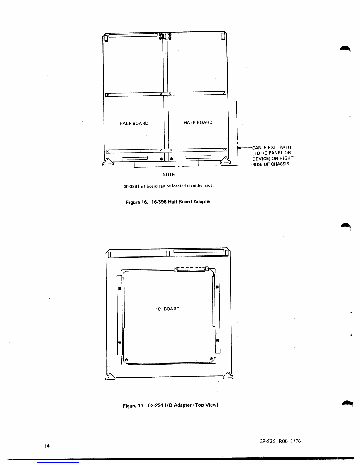
one active and one blank 7 inch board, depending on requirements. A 10 inch I/O Controller (provided
it
does
not
use Connector 1) may be inserted via the 02-234 I/O Adaptor Kit (see Figure 17).
No
wiring takes place between
the
boards and
the
adaptors. The adaptors are assigned such
that
the connectors on the boards plug directly
into
the
chassis.
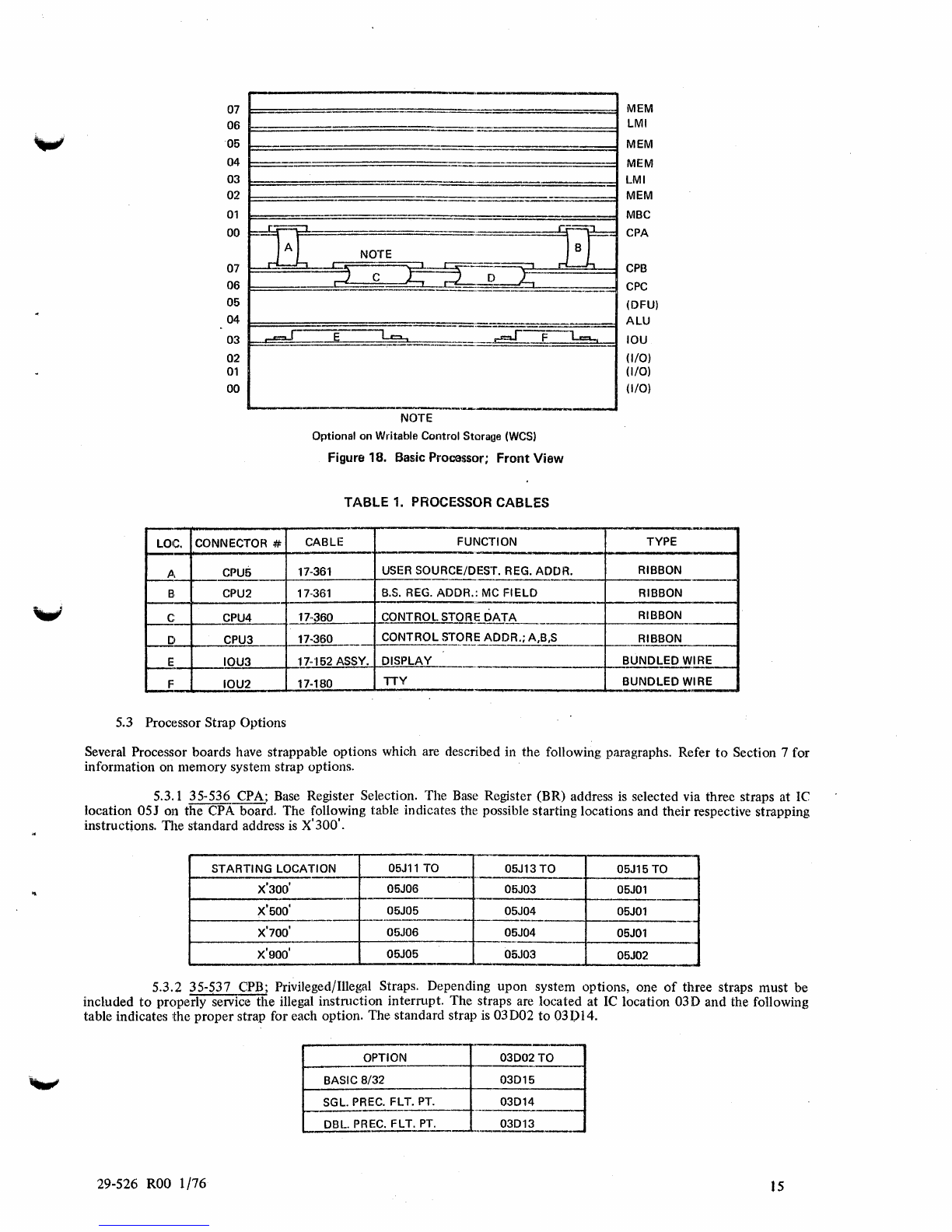
Figure 18
is
a configuration
of
the Basic Processor chassis
as
viewed from the Display Panel side.
It
correlates applicable
cables
to
the associated Processor connectors and Table 1 lists the function
of
each cable.
Figure 19 uepicts the Basic Processor Chassis
as
viewed from the back plane. Shown here are the 35-578 Local Memory
Bus
(LMB) Terminator, the 35-596 Control Address (CA) Terminator, the 17-336 EDMA Cable Assembly, and
the
35-569
Processor Terminator. Note
that
one end
of
the 17-336 Cable Assembly has a terminator card. This end
of
the cable must
always be installed on upper Slot
1,
Connector I side. ll1e
other
end
of
17-336
is
shown connected
to
lower Slot
2,
Con-
nector 1 side
but
may also be connected
to
lower Slots 0
or
1.
29-526
ROO
1/76 13
....,
07 MEM
06 LMI
05 MEM
04
--
MEM
03
..
_--
.--
LMI
02 ---= MEM
01
MBC
00
r~=:::::;-"1
rr::=::;, CPA
==
F=-'--'
C
A NOTE
07
~-h
rJ
~:=r:
~-~~~
CPB
06
CPC
--
05 (DFU)
04
ALU
03
~-
~
~--~---~
F
-~
IOU
02
(1/0)
01
(//0)
00
(1/0)
--,------
.•
---------
NOTE
Optional on Writable Control Storage
(WCS)
Figure 18. Basic Procassor; Front View
TABLE
1.
PROCESSOR CABLES
---
LaIC. CONNECTOR # CABLE FUNCTION TYPE
---
-
fj, CPU5 17-361 USER SOURCE/DEST. REG.
ADDR.
RIBBON
B:
CPU2 17·361
B.S.
REG.
ADDR.:
MC
FIELD
RIBBON
c:
CPU4 17-360
~ONTROLSTO~~Q~~A
RIBBON
D CPU3 17-360
CONTROL
STg_~~DDR.;
A,B,S
-l--.......:.f!
IBBON
__
r---!~
IOU3
17·'152 ASSY.
DISPLAY
-+-...-;;BUNDLED
~!B.L.
F
IOU2
17-180
TTY
BUNDLED
WI
RE
-
5.3 Processor Strap Options
Several Processor boards have strappable options which are described in the following paragraphs. Refer
to
Section 7 for
information on memory system strap options.
5.3.1 35-536 CPA;
Base
Register Selection. The
Base
Register (BR) address
is
selected via three straps at
Ie
location
05J
on the CPA board. The following table indicates the possible starting locations and their respective strapping
instructions. TIle standard address
is
X'300'.
STARTING
LOCATION
05Jll
TO 05J13
TO
05J15
TO
---,
X'300'
05J06 05J03 05JOl
.•
---
X'500'
05J05 05J04 05JOl
--
---
X'700' 05J06 05J04 05JOl
..
.-
.
X'900'
05J05 05J03 05J02
...
5.3.2 35-537 CPB; Privileged/Illegal Straps. Depending upon system options, one
of
three straps must be
included
to
properly service the illegal instruction interrupt. The straps are located at
Ie
location 03D and the following
table indicates
:the
proper strap for each option. The standard strap
is
03D02
to
031)14.
--
OPTION
03002
TO
BASIC 8/32
03015
SGL. PREC.
FL
T.
PT.
03014
t---
.....
DBL. PREC. FLT.
PT.
03013
-- .
.-
29-526
ROO
1/76
IS
If the Writable Control Store
(WCS)
option
is
added, a different PRIV/ILLEG
ROM
must
be
used; however, the straps are
the same.
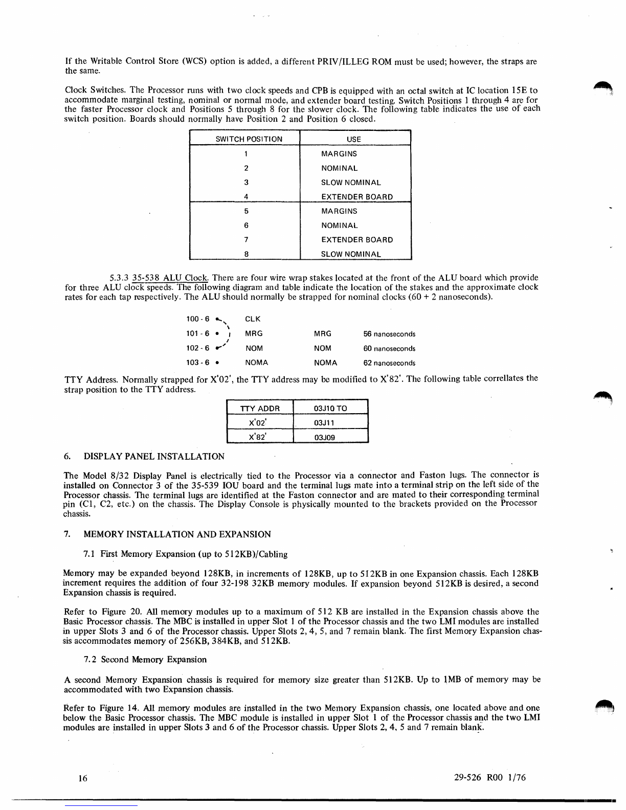
Clock Switches. The Processor runs with two clock speeds and
CPB
is
equipped with
an
octal switch at
IC
location 15E
to
accommodate marginal testing, nominal or normal mode, and extender board testing. Switch Positions 1 through 4 are for
the faster Processor clock and Positions 5 through 8 for the slower clock. The following table indicates the use
of
each
switch position. Boards should normally have Position 2 and Position 6 closed.
SWITCH POSITION
USE
1 MARGINS
2
NOMINAL
3 SLOW
NOMINAL
4 EXTENDER BOARD
5 MARGINS
6
NOMINAL
7 EXTENDER BOARD
8 SLOW
NOMINAL
5.3.3 35-538 ALU Clock. There are four wire wrap stakes located at the front
of
the ALU board which provide
for three ALU clock speeds. The following diagram and table indicate the location
of
the stakes and the approximate clock
rates for each tap respectively. The ALU should normally be strapped for nominal clocks (60 + 2 nanoseconds).
100 - 6
....
"
ClK
\
101
- 6 • , MRG MRG 56 nanoseconds
I
102·6
r"
NOM NOM 60 nanoseconds
103·6
• NOMA NOMA 62 nanoseconds
TTY Address. Normally strapped for X'02', the TTY address may
be
modified
to
X'82'. The following table correllates the
strap position
to
the TTY address.
TTY
ADDR
03J10
TO
x'o2'
03Jll
X'82'
03J09
6.
DISPLAY PANEL INSTALLATION
The Model
8/32
Display Panel
is
electrically tied
to
the Processor via a connector and Faston lugs. The connector is
installed
on
Connector 3
of
the 35-539 IOU board and the terminal lugs mate
into
a terminal strip on the left side
of
the
Processor chassis. The terminal lugs are identified at the Faston connector and are mated
to
their corresponding terminal
pin (CI, C2, etc.) on the chassis. The Display Console
is
physically mounted
to
the brackets provided on the Processor
chassis.
7.
MEMORY INSTALLATION AND EXPANSION
7.1
First Memory Expansion (up
to
512KB)/Cabling
Memory may be expanded beyond 128KB, in increments
of
128KB, up
to
5I2KB in one Expansion chassis. Each 128KB
increment requires the addition
of
four 32-198 32KB memory modules.
If
expansion beyond 512KB is desired, a second
Expansion chassis
is
required.
Refer
to
Figure 20.
All
memory modules up
to
a maximum
of
512
KB
are installed in the Expansion chassis above the
Basic Processor chassis. The
MBC
is
installed in upper Slot 1
of
the Processor chassis and the two
LMI
modules are installed
in upper Slots 3 and 6
of
the Processor chassis. Upper Slots
2,4,
5, and 7 remain blank. The first Memory Expansion chas-
sis
accommodates memory
of
256KB, 384KB, and 5l2KB.
7.2 Second Memory Expansion
A second Memory Expansion chassis
is
required for memory size greater than 512KB. Up
to
1MB
of
memory may be
accommodated with two Expansion chassis.
Refer
to
Figure 14. All memory modules are installed in the two Merhory Expansion chassis, one located above and one
below the Basic Processor chassis. The
MBC
module
is
installed in upper Slot 1
of
the Processor chassis and the
two
LMI
modules are installed in upper Slots 3 and 6
of
the Processor chassis. Upper Slots
2,
4, 5 and 7 remain
blan~.
16
29-526
ROO
1/76
----------------------------------------------------------------------------------------------------------------........-
Table of contents
Popular Desktop manuals by other brands


BOSTONtec
BOSTONtec CPU12 Mounting instructions

IEI Technology
IEI Technology IBX-700 Series user manual

Aegis
Aegis MS-B901 Service manual

Intergraph
Intergraph Zx1 ViZual Workstation System guide

Lenovo
Lenovo THINKCENTRE M810z 10NX User guide and hardware maintenance manual

Dell
Dell Inspiron 2100 user guide