EMBRON Hatteland X G2 Series User manual

Please visit www.hattelandtechnology.com for the latest electronic version of this manual.
HD 19T22 MxC-yyy-yyyyyy - 19.0 inch Maritime Multi Computer
HD 24T22 MxC-yyy-yyyyyy - 24.0 inch Maritime Multi Computer
HD 26T22 MxC-yyy-yyyyyy - 25.54 inch Maritime Multi Computer
HD 27T22 MxC-yyy-yyyyyy - 27.0 inch Maritime Multi Computer
(where x is either; M=Standard (MMC), E=ECDIS Calibrated (MEC)
(where y=congurations/factory options)
Series X G2 - Maritime Multi Computer (MMC) Models
USER MANUAL
User Manual MMC Series X G2
Updated: 07 Jul 2021 Doc Id: INB101191-1 (Rev 11)
Created: 363 Approved: 6987

Copyright © 2021 Hatteland Technology AS
Eikeskogvegen 52, N-5570 Aksdal, Norway.
All rights are reserved by Hatteland Technology AS. This information may not, in whole or in part, be
copied, photocopied, reproduced, translated or reduced to any electronic medium or machine-
readable form without the prior written consent of Hatteland Technology AS. Review also:
www.hattelandtechnology.com/hubfs/pdf/misc/doc100703-1_permission_to_create_user_manuals.pdf
The products described, or referenced, herein are copyrighted to the respective owners.
The products may not be copied or duplicated in any way. This documentation contains proprietary
information that is not to be disclosed to persons outside the user’s company without prior written consent
of Hatteland Technology AS.
The copyright notice appearing above is included to provide statutory protection in the event of
unauthorized or unintentional public disclosure.
All other product names or trademarks are properties of their respective owners !
WARNING: This is a class A product. In a domestic environment this product may cause radio interference
in which case the user may be required to take adequate measures.
Statement above last revised 31 Jul. 2019

3
IND100130-55
Contents.......................................................................................... 3
Contents of package............................................................................................................... 8
General .......................................................................................... 11
IEC62368 policy - Introduction ............................................................................................. 12
About this manual................................................................................................................. 13
About Hatteland Technology................................................................................................. 13
www.hattelandtechnology.com ............................................................................................. 13
Contact Information .............................................................................................................. 13
Maritime Multi Computer (MMC) Generation 2 (G2) - Introduction ...................................... 14
Product Labeling................................................................................................................... 15
Touch screen products ......................................................................................................... 18
Installation..................................................................................... 21
General Installation Recommendations................................................................................ 22
First Things First! .................................................................................................................. 22
Installation and mounting...................................................................................................... 22
Installation limitations ........................................................................................................... 23
Ergonomics........................................................................................................................... 25
Cables .................................................................................................................................. 26
Cable Entries & Connectors (Marked area) ...................................................................... 26
Maximum Cable Length .................................................................................................... 26
Housing / Terminal Block Connector Overview .................................................................... 27
Panel Cutout / Console Mounting Bracket Kit for 19 inch..................................................... 29
Panel Cutout / Console Mounting Bracket Kit for 24 and 27 inch......................................... 31
Panel Cutout / Console Mounting Bracket Kit for 26 inch .................................................... 32
Mounting Bracket, Table / Desktop / Ceiling - 15, 17 and 19 inch ........................................ 33
Mounting Bracket, Table / Desktop / Ceiling - 24, 26 and 27 inch ........................................ 35
Physical Connections ........................................................................................................... 37
COM Ports Numbering ........................................................................................................ 41
Operation....................................................................................... 43
User Controls........................................................................................................................ 44
Contents

Contents
4
IND100130-55
Specications ............................................................................... 47
Specications - HD 19T22 MxC-xxx-xxxxxx......................................................................... 48
Specications - HD 24T22 MxC-xxx-xxxxxx......................................................................... 49
Specications - HD 26T22 MxC-xxx-xxxxxx......................................................................... 50
Specications - HD 27T22 MxC-xxx-xxxxxx......................................................................... 51
Specications - CAN Module with CO-Processor................................................................. 52
ZIA0001310-B ................................................................................................................... 52
Specications - NMEA / IEC COM Module RS-422 / RS-485 .............................................. 53
PCA200828-1.................................................................................................................... 53
Specications - Isolated Digital Input/Output Module ........................................................... 57
PCA100297-1.................................................................................................................... 57
Specications - LAN Module ................................................................................................ 59
PCA100298-1.................................................................................................................... 59
Specications - Isolated COM Module RS-232 .................................................................... 60
PCA100309-1.................................................................................................................... 60
Specications - NMEA / IEC COM + Digital IO Module........................................................ 61
Q170 IO............................................................................................................................. 61
Specications Accessories ......................................................... 65
Specications - JH C01MF A-A ............................................................................................ 66
Specications - External Modules (USB).............................................................................. 67
Technical Drawings ...................................................................... 69
Technical Drawings - HD 19T22 MxC-xxx-xxxxxx ................................................................ 70
Technical Drawings - HD 24T22 MxC-xxx-xxxxxx ................................................................ 71
Technical Drawings - HD 26T22 MxC-xxx-xxxxxx ................................................................ 72
Technical Drawings - HD 27T22 MxC-xxx-xxxxxx ................................................................ 73
Technical Drawings - Accessories.............................................. 75
Technical Drawings - HD CMB SX2-N1................................................................................ 76
Console Mount Kit 19 inch ................................................................................................ 76
Technical Drawings - HD CMB SX2-E1................................................................................ 77
Console Mount Kit 24 inch ................................................................................................ 77
Console Mounting 24 inch................................................................................................. 78
P006801-1 Flush Mounting 24 inch................................................................................... 79
Technical Drawings - HD CMB SX2-F1 ................................................................................ 80
Console Mount Kit 26 inch ................................................................................................ 80
Console Mounting 26 inch................................................................................................. 81
P007084-1 Flush Mounting 26 inch................................................................................... 82
Technical Drawings - HD CMB SX2-E1................................................................................ 83
Console Mount Kit 27 inch ................................................................................................ 83
Console Mounting 27 inch................................................................................................. 84
P020721 - Flush Mounting 27 inch.................................................................................... 85
Technical Drawings - HD VED SX2-C1 ................................................................................ 86
VESA Adapter 19 inch....................................................................................................... 86

Contents
5
IND100130-55
Technical Drawings - HD VED SX2-H1 ................................................................................ 87
VESA Adapter 24, 26, 27 inch........................................................................................... 87
Technical Drawings - HD VED SX2-I1.................................................................................. 88
VESA Adapter 24 inch....................................................................................................... 88
Technical Drawings - HD VED SX2-J1 ................................................................................. 89
VESA Adapter 26 inch....................................................................................................... 89
Technical Drawings - HD VED SX2-K1 ................................................................................ 90
VESA Adapter 27 inch....................................................................................................... 90
Technical Drawings - JH 19TAP STD-C1 ............................................................................. 91
19 inch Series X to t 19 inch Series 1 Console Cutout.................................................... 91
Technical Drawings - HD 19TAP SX2-C2............................................................................. 92
19 inch Series X to t 19 inch Series 2 Console Cutout.................................................... 92
Technical Drawings - JH 26TAP STD-A1.............................................................................. 94
26 inch Series X to t 26 inch Series 1 Console Cutout.................................................... 94
Technical Drawings - HD 26TAP SX1-A1 ............................................................................. 95
26 inch Series X to t 27 inch Series 1 Console Cutout.................................................... 95
Technical Drawings - HD TMB SX2-A1 ................................................................................ 96
Desktop/Table Mounting Bracket 19 inch.......................................................................... 96
Technical Drawings - HD TMB SX1-C1 ................................................................................ 97
Desktop/Table Mounting Bracket 24/26/27 inch................................................................ 97
Desktop/Table Mounting Bracket 24 inch.......................................................................... 98
Desktop/Table Mounting Bracket 26 inch.......................................................................... 99
Technical Drawings - HD 19COV SX1-A1 .......................................................................... 100
UV Sun Cover (19 inch) .................................................................................................. 100
Technical Drawings - HD 24COV SX1-A1 .......................................................................... 101
UV Sun Cover (24 inch) ................................................................................................. 101
Technical Drawings - HD 26COV SX1-A1 .......................................................................... 102
UV Sun Cover (26 inch) .................................................................................................. 102
Technical Drawings - HD 27COV SX1-A1 .......................................................................... 103
UV Sun Cover (27 inch) ................................................................................................. 103
Technical Drawings - HD CAK SX2-A1 .............................................................................. 104
Front Console Mounting/Adapter Kit (24 inch) ................................................................ 104
Technical Drawings - HD CAK SX2-B1 .............................................................................. 105
Front Console Mounting/Adapter Kit (27 inch) ................................................................ 105
Technical Drawings - P007131-1........................................................................................ 106
IP66 Panel Gasket (19 inch) ........................................................................................... 106
Technical Drawings - P022211 .......................................................................................... 107
IP66 Panel Gasket (24 inch) ........................................................................................... 107
Technical Drawings - P007178 ........................................................................................... 108
IP66 Panel Gasket (26 inch) ........................................................................................... 108
Technical Drawings - P018743 ........................................................................................... 109
IP66 Panel Gasket (27 inch) ........................................................................................... 109
Technical Drawings - External Modules (USB)....................................................................110

Contents
6
IND100130-55
Appendixes ..................................................................................111
SSD Selection Guide...........................................................................................................112
BIOS Default Settings Overview..........................................................................................116
Pinout Assignments ............................................................................................................ 123
IEC62368 policy for Hatteland Technology products.......................................................... 126
Basic Trouble-shooting ....................................................................................................... 128
Trouble-shooting................................................................................................................. 129
Operating System Recovery (tool) .................................................................................... 129
How to activate Windows Recovery Environment on OS Drive ........................................ 133
Declaration of Conformity ................................................................................................... 134
Return Of Goods Information ............................................................................................. 135
General Terms and Conditions ........................................................................................... 136
Pixel Defect Policy.............................................................................................................. 137
Parts and Recycling............................................................................................................ 138
Notes .................................................................................................................................. 139
Revision History.................................................................................................................. 141

7
This page left intentionally blank

8
IND100131-36
Contents of package
Item Description Illustration
TP52/TC01-1,8M
1 pcs of power cable European Type F “Schuko” to IEC.
Length 1.8m
EUR TYPE F
IEC
TP11/TC01-1,8M
1 pcs of power cable US Type B plug to IEC.
Length 1.8m
US TYPE B IEC
Test Reports papers:
1 pcs of Product Declaration
1 pcs of Computer Checklist
1 pcs of BurnInTest Certificate
HD CMB SX2-N1
Model Dependent: Bracket Kit suitable for console/panel mounting which contains:
2 x xxT22 Console Bracket (P019774#02)
4 x RAMPA-CAP NUTS TYPE RF 10 15 X 9 M5, STEEL ZINC PL. HEX4 (025509001)
6 x CSK Screws M5x12 Hex Zinc blank. Kval. 10.9 (145 050x012 SZF)
4 x KNURLED KNOB M5 UMBR. Ø=17 mm, 038 0500 599 05 - BLACK (222 38-5 BLACK)
4 x Socket Head Cap Screw M5x70 DIN912/ISO4762 A4 Fully Threaded (145 050x070 912 A4F)
Suitable for panel thickness min: 2.0 [0.08”] to max 55.50 [2.18”] mm [inch].
The bracket kit is suitable for 19 inch units and is EN60945 Tested.
HD CMB SX2-E1
Model Dependent: Bracket Kit suitable for console/panel mounting which contains:
3 x Mounting Bracket for top, left and right side (P006858-1)
1 x Mounting Bracket for bottom side (terminal/connector plate area) (P020605)
6 x M5x16 Pan Head screw ISO 14583 Torx, A4 screws (145 050x016 A4T)
6 x M6 C-washers DIN6319 Steel (144 064x120x22)
2 x DIN 965 M5x16 Countersunk head screws with TX25, A4 STAINLESS STEEL (145 050x016 CA4)
Suitable only for 24 and 27 inch units and is EN60945 Tested.
HD CMB SX2-F1
Model Dependent: Bracket Kit suitable for console/panel mounting which contains:
4 x Mounting Bracket for top, left, right and bottom side (P007085-1)
8 x Panskrue M5x16 Torx, blank (145 050X016 ZT)
8 x M6 C-washers DIN6319 Steel (144 064x120x22)
Suitable only for 26 inch units and is EN60945 Tested.
Terminal Block Connector Kit
Terminal Block Connector Kit as follows (may in some cases be already factory mounted):
1 x 2-pin Terminal Block 5.08 (1961986) for DC Power In
Refer to “Conguring Housing / Terminal Block Connector” section for usage. Note: Location of module(s) may
dier between unit sizes
Note: Entries listed below are for Standard factory shipments. Customized factory shipments may deviate from this list.

9
IND100131-36
Item Description Illustration
Terminal Block Connector Kit
Depending on factory mounted options, Terminal Bracket Connector kit as follows:
4 x 5-pin Terminal Block 3.81 for RS-422 / RS-485 NMEA COM (PCA200828-1 / PCA100293-1)
4 x 4-pin Terminal Block 3.81 for CAN Interface (ZIA0001310-B)
4 x 5-pin Terminal Block 3.81 for Digital Input/Output (PCA100297-1)
2 x 5-pin Terminal Block 3.81 for RS-422 / RS-485 NMEA COM + Digital Input/Output (Q170 IO) Note: Location of module(s) may
dier between unit sizes
1 x IP66 Mount Gasket for Size ordered.
Details: EPDM material
Glue: Duplocoll
Surface: RAL9011
P007131-1 (19), P022211 (24 inch), P007178 (26 inch), P018743 (27 inch)
Package may also include: (based on accessories/options ordered)

10
This page left intentionally blank

11
General
12
IND100078-81
General
IEC62368 policy - Introduction
Safety Instructions
Please read and understand the material in the manual in its entirety before doing any installation/servicing/upgrades.
Personnel who are allowed to do work on the unit is detailed in the “IEC62368 policy for Hatteland Technology
product” section later in this manual. Symbols pertaining to different personnel in regard to operations is described in
the user manual.
Based on requirements EN 62368-1:2014 and IEC 62368-1:2018
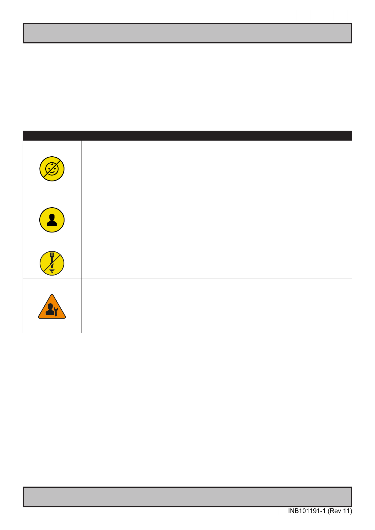
Authority Description
Children This equipment is not suitable for use in locations where children are likely to be present.
Ordinary person/
Sailor/End-User
Not allowed to open unit.
Not allowed to install the unit.
Not allowed to terminate/connect cables to the unit.
Instructed person Allowed to open hatches/latches which does not require tools, such as Disktrays.
Allowed to open "battery-hatch" to change the battery even if tools are required.
Allowed to install the unit.
Allowed to terminate/connect cables to the unit indoors.
Skilled person Allowed to open and disassemble the unit.
Allowed to install the unit.
Allowed to terminate/connect cables to the unit indoors and outdoors.
Allowed to terminate/connect earth/ground wire.
Note: Be aware that additional denition for “skilled person” may apply, country dependent.
13
Hatteland Technology AS
IND100077-1
General
About this manual
The manual contains electrical, mechanical and input/output signal specications. All specications in this manual,
due to manufacturing, new revisions and approvals, are subject to change without notice. However, the last updated
and revision date of this manual are shown both on the frontpage and also in the “Revision History” chapter. This
user manual is a standard/general manual that applies to all variations of its product family, i.e. deviation from actual
conguration may exist.
About Hatteland Technology
Hatteland Technology is the leading technology provider of specialized display and computer products, delivering high
quality, unique and customized solutions to the international maritime, naval and industrial markets.
The company represents innovation and quality to the system integrators worldwide. Effective quality assurance and
investment in sophisticated in-house manufacturing methods and facilities enable us to deliver Type Approved and Mil
tested products. Our customer-oriented approach, technical knowledge and dedication to R&D, makes us a trusted
and preferred supplier of approved solutions, which are backed up by a strong service network.
www.hattelandtechnology.com
You will nd our website full of useful information to help you make an informed choice as to the right product for your
needs. You will nd detailed product descriptions and specications for the entire range on Displays, Computers and
Panel Computers, Military solutions as well as the range of supporting accessories. The site carries a wealth of
information regarding our product testing and approvals in addition to company contact information for our various
oces around the world, the global service locations and the technical help desk, all ensuring the best possible
support wherever you, or your vessel, may be in the world.
Contact Information
Head oce, Aksdal / Norway:
Hatteland Technology AS
Eikeskogvegen 52
N-5570 Aksdal, Norway
Switchboard:
Tel: +47 4814 2200
mail@hattelandtechnology.com
Sales oce, Frankfurt / Germany:
Hatteland Technology GmbH
Werner Heisenberg Strasse 12,
D-63263 Neu-Isenburg, Germany
Uwe Scheumann:
Tel: +45 2463 9565
Elke Freisens:
Tel: +49 173 6174753
Sales oce, Oslo / Norway:
Hatteland Technology AS
Strandveien 35
N-1366 Lysaker
Norway
Switchboard:
Tel: +47 4814 2200
mail@hattelandtechnology.com
Sales oce, Aix-en-Provence / France:
Hatteland Technology SAS
Actimart- 1140, rue Ampère, CS 80544
13594 Aix-en-Provence, Cedex 3
France
Mehdi Bounoua (Sales Director Europe, Middle East & Africa):
Tel : +33 6 88 33 64 93
Sales oce, Vista / USA:
Hatteland Technology Inc
450 South Melrose Drive,
Suite #107
Vista, CA 92081
USA
Donna Pallonetti:
Tel: +1 858-282-0659
Fax: +1 858-408-1834
For an up-2-date list, please visit https://www.hattelandtechnology.com/contact
14
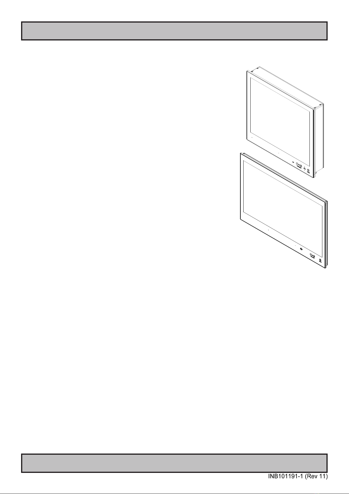
Panel Computers Series X Generation 2 (G2)
IND101057-17
General
Maritime Multi Computer (MMC) Generation 2 (G2) - Introduction
Integrating powerful Intel Skylake/Kaby Lake processor-based computers, high
quality display technology and advanced video processing, Hatteland Technology’s
second generation Series X Panel Computers are the most powerful all-in-one
computer/display solution available for maritime technology manufacturers and
systems integrators available today.
The second generation Series X Panel Computers are available for a diverse
range of applications. The large format models are especially suitable for the new
wave of modern Integrated Bridge System designs created to accommodate a new
data-centric approach to vessel navigation and safety. With powerful computers
integrated in the display housing, bridge system designers have unmatched
flexibility to create far more ergonomic layouts, which are easier to install due to
significantly reduced cabling requirements.
The integrated nature of Hatteland Technology’s second generation Series X
Panel Computers also enables tangible cost savings for equipment manufacturers
and systems integrators. Hatteland Technology’s Panel Computers provide
the same power and picture quality as a standard display and separate PC
configuration, but with lower capital expenditure (relative to purchase of separate
displays and computers) and installation costs, they can be used as the basis
of cost reduction programs. This makes it possible for technology integrators to
continue improving vital bridge applications while still retaining focus on cost for
their partners and end-customers.
The expansion of the second generation Series X portfolio to include larger Panel
Computer models provides more flexibility for equipment manufacturers to utilise
the most powerful computers and highest quality displays in a wider range of
vessel technology, especially on the bridge.
A computer and display, all in one...
- MULTITOUCH
- Type Approved
- ECDIS Compliant
- IP20 rear / IP66 front - IP22=Option
- Superior Bonding Technology
- Module based, tailor-made systems made easy!
- Sunlight Readable / High Bright versions available
- GLASS DISPLAY CONTROL™ (GDC), Solid State Menu System

15
IND100077-172
Product Labeling
Introduction
This section details the locations, content details and specications for factory mounted labels for all currently
available standard Hatteland Technology Panel Computer (MMC) models. This information will in most cases also
apply for most Customized Models as well, but may dier based on customer requirements, in that case, please refer
to the customized User Manual (paper or electronic version, dependent on customer requirements).
Label Size and Types
ID Label Layout Description Specication
Type : Serial Number Label
Name : Label B
Size : 60mm wide x 20mm high (rectangle size)
Note: Text content of label will match specications
derived from Data Sheet.
Silver with glue on back, non-
tearable and made for thermal
transfer printing.
Barcode type: CODE128 (used extensively world wide in shipping and packaging
industries. The symbology was formerly dened as ISO/IEC 15417:2007.)
Type : Operating System (OS) label.
Size : 70mm wide x 23mm high (rectangle size)
Note: Label only present if OS was part of factory
option order. Linux OS does not have any label.
As per delivered from supplier.
Label applies for:
Windows® 7 Professional
Windows® 7 Ultimate
Type : Operating System (OS) label.
Size : 22mm wide x 9mm high (rectangle size)
Note: Label only present if OS was part of factory
option order. Linux OS does not have any label.
As per delivered from supplier.
Label applies for:
Windows® Emb. Standard 7
Windows® 10 IoT Enterprise
Type : Touch Screen Label
Name : Label B
Size : 60mm wide x 20mm high (rectangle size)
Note: Only present if Touch Screen was part of factory
option order.
Silver with glue on back, non-
tearable and made for thermal
transfer printing.
Note: Content on label will vary based on Touch Screen type and/or Touch Screen
Controller. Label shown to the right is for illustration purposes only!
Type : Warranty Label
Size : 30mm wide x 23mm high (oval size)
Tamper-proof sticker with glue on
back.
Type : Quality Control (QC) Label
Size : 30mm wide x 23mm high (oval size)
Ordinary sticker with glue on
back.
Type : Handling Symbols Label
Size : 16mm wide x 8mm high (rectangle size)
Symbols indicate Cadmium Free product and proper
waste handling required.
FLEXcon®PHARMcal®V 400 F
WhiteTC-848V-23 TRACrite™150
Type : Shock Hazard Caution Label
Name : Label B
Size : 60mm wide x 20mm high (rectangle size)
Silver with glue on back, non-
tearable and made for thermal
transfer printing.
Rules specied in IEC62368-1:2018 annex L.8 and F.5. Applies for units with Dual/Multi-
Power inputs only (more than 1 Power Input).

16
Product Labeling
IND100077-172
Label Locations
Number ID and coloring based on “Label Size and Types“ table from previous page. All illustrations below are seen
from rear (and side where needed) with connectors facing down. Actual labels regarding its size and text orientation
vs product size is drawn in. Due to space restrictions on selected units, some labels will be rotated 90 degrees to t
properly. The arrangement of labels may be shifted/stacked dierently as it is based on factory options, such as; Touch
Screen and Operating System (OS), but they will be grouped together where possible.
Label Positions Notes Applies for Product Range
Warranty label covers screw.
Labels placed on rear.
HD 19T22 MxC-xxx-xxxxxx
Warranty label covers screw.
Labels placed on rear.
HD 24T22 MxC-xxx-xxxxxx
Warranty label covers screw.
Labels placed on rear.
HD 26T22 MxC-xxx-xxxxxx
Warranty label covers screw.
Labels placed on rear.
HD 27T22 MxC-xxx-xxxxxx

17
Product Labeling
IND100077-174
Warranty Label
If you are to perform service on a unit still under warranty, any warranty will be void if this label show signs of removal
attempts or damaged by screw driver. This label is located on the back of the product and covers a key screw. This is
to aid service departments in determining if there has been any unauthorized service on a unit still under warranty.
Quality Control (QC) Label
This label indicates that the unit is produced, tested and packed according to the manufacture’s QA specications. It
will include a Personal ID and signature by the personnel responsible for approving the unit in production, testing and
warehouse departments.
Handling Symbols Label
Ecodesign Requirements for Electronic Displays. The European Union published the Regulation 2019/2021 with
specic environmental ecodesign requirements for various types of electronic displays, such as TVs, monitors, and
digital signage displays.
Reference: https://www.enviropass.ca/2021/03/01/5-ecodesign-requirements-for-electronic-displays/
Serial Number Label Layout (example)
Please note that typenumber shown above is a generic sample only. May not reect products mentioned in this
manual. Please review actual product S/N label.
Manufacturer/Country
Input Voltage(s)
Type+Serial Number
Barcode (TYP+SNO)
Power Rating Max/Typ
Date of Production (YYYY-MM-DD)
Compass Safe Distance
IP Rating
Lowest value used, higher may apply,
check specications.

18
IND100110-12
Touchscreen
Introduction to products with touch screen
Nearly all of our products with touch screen use Projected Capacitive Touch screen (PCTS), widely used with great
success on mobile phones and typical pad devices. PCTS can be equally eective also for marine applications.
One of the advantages of PCTS is that it has features seen in both resistive and surface capacitive touch screen
technologies.
Multitouch is dened as the ability to recognize two or more simultaneous touch points. Using projected capacitive
technology allows us to create a more intuitive form of human-device interaction. Touch interface gestures, supported by
projected capacitive sensors, can simplify the interface and provide an intuitive user experience that goes beyond the
typical "button replacement" found in most simple touch interfaces.
Please review the appropriate Product Datasheet (in this manual) to determine if PCTS are supported and/or its
advanced features of additional touch methods (example Tactor and Active Stylus Pen) are available.
The technical benets of PCTS are:
- Very good optical performance (same as surface capacitive)
- Environmentally strong, the touch sensor is inside the product (better than both surface capacitive and resistive)
- Supports Multitouch (Newer Operating System (OS) required in most cases.
- Excellent readability - light transmission of up to 91% through a standard sensor
- Stability - no drift, therefore no recalibration is required
- Pointing device - works with gloved and ungloved finger
- Resistance to contamination - by harsh cleaning fluids and other noxious substances
- Communicates via USB to external computer or internally
Comparisons between general Touch Technologies used by Hatteland Technology:
Technology Optical Performance Gloves Water Durability Multitouch Stylus Objects (Tactor)
Analog Resistive -- ++ ++ - - - --
Surface Capacitive ++ -- - + - - --
Projected Capacitive ++ + + *++ ++ ++ ++
*Projected Capacitive (PCTS) / Water: Touch Screen Glass Surface can withstand drip and direct rain, but expect reduced capability, detection and
performance if units are exposed to these factors while powered. Hatteland Technology recommends protecting the unit from direct rain or drips if
critical touch operations are to be performed. Take necessary steps (if detected or suspected) within the installation environment to prevent accidental
touch gestures or presses not performed intentionally by a human operator.
Touch screen products

19
Touch screen
IND100110-22
Touch Screen Products
Touch Screen Drivers
All units with Touch Screens are automatically detected by the Operating System via HID. There is no need to install
additional Third-Party touch screen drivers.
Microsoft® Windows® Svr Emb Std 2012 / Microsoft® Windows® 7 / Microsoft® Windows® 10 IoT:
- Please use Windows® Generic HID driver, no specic driver needed to use multi-touch.
- Alternative conguration available: See “Mouse Mode feature” below.
Microsoft® Windows® XP:
Ref: OS End-of-Life:
https://www.hattelandtechnology.com/product-notications/update-eol-microsoft-windows-xp-professional-for-embedded-systems-and-
microsoft-windows-xp-embedded
- Multi-Touch Screen is not supported for this Operating System.
- Alternative Single Touch / Mouse Mode is however supported via alternative parameter les.
Ref: https://www.hattelandtechnology.com/product-notications/new-touchscreen-solution-series-x-g2-mmd-15-17-19-inch
Information, Tools and Parameters les can be downloaded from:
https://www.hattelandtechnology.com/hubfs/drivers/t22_singletouch_mousemode_tools_and_parameters.zip
If you experience any deviation in the touch input accuracy, consider re-calibrating the touch screen for your system.
Please use the standard Operating System functionality to calibrate.
Example for Microsoft® Windows® 10 IoT:
1.Open Control Panel.
2.Click on Hardware and Sound.
3.Under “Tablet PC Settings,” click the Calibrate the screen for pen or touch input link.
4.Under “Display options,” select the display (if applicable).
5.Click the Calibrate button.
6.Select the Touch input option
Example for Microsoft® Windows® 7:
1: Open Control Panel
2: Open “Tablet PC Settings”
3: Under “Display options,” select your display.
4: Click the Calibrate button and follow instructions
5: To save settings, click “Apply” or “OK” on the “Table PC Settings” window.
Mouse Mode feature:
The Multi-Touch screen interface can be congured to support mouse emulation to support certain legacy software.
If your system and its GUI (Graphical User Interface) experience lack of response to gadgets/buttons pressed via
touch screen, the package below might help. This feature works from Microsoft® Windows® XP and up.
Please note that Multi-touch will be disabled and replaced by Single Touch mode.
https://www.hattelandtechnology.com/hubfs/drivers/t22_singletouch_mousemode_tools_and_parameters.zip
ref: https://www.hattelandtechnology.com/product-notications/new-touchscreen-solution-series-x-g2-mmd-15-17-19-inch
Linux
- Please use Linux Generic Touch driver.
Note: Kernel before 2.6.38: Single touch support.
Note: Kernel above 2.6.38: Multi touch support.
Note: For optimal graphical performance/hardware support with Skylake/Kaby Lake CPU’s on T22 MMC units, the
Linux Kernel 4.4 or later is required/recommended.

20
Touch Screen Products
Touch screen
IND100110-22
Touch Screen Calibration
If you experience any deviation in the touch input accuracy, consider re-calibrating the touch screen for your system.
Procedures below are for standard Microsoft® Windows® Operating System calibrate functions.
Example for Microsoft® Windows® 10 IoT:
1.Open Control Panel.
2.Click on Hardware and Sound.
3.Under “Tablet PC Settings,” click the Calibrate the screen for pen or touch input link.
4.Under “Display options,” select the display (if applicable).
5.Click the Calibrate button.
6.Select the Touch input option.
Example for Microsoft® Windows® 7:
1: Open Control Panel.
2: Open “Tablet PC Settings”.
3: Under “Display options,” select your display.
4: Click the Calibrate button and follow instructions.
5: To save settings, click “Apply” or “OK” on the “Table PC Settings” window.
This manual suits for next models
4
Table of contents
Other EMBRON Desktop manuals

EMBRON
EMBRON Hatteland Display HT B22G Series User manual

EMBRON
EMBRON Hatteland X Series User manual

EMBRON
EMBRON Hatteland E Series User manual

EMBRON
EMBRON HATTELAND HT B30G STC M Series User manual

EMBRON
EMBRON Hatteland HT20 70 Series User manual

EMBRON
EMBRON HATTELAND TECHNOLOGY HT C02H STC Series User manual

EMBRON
EMBRON Hatteland Technology HTC03 AC Series User manual

EMBRON
EMBRON HATTELAND HD 08T30 Series User manual


