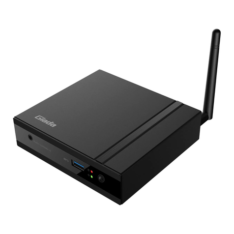
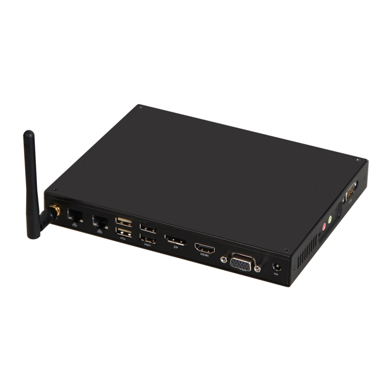
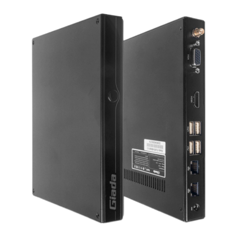
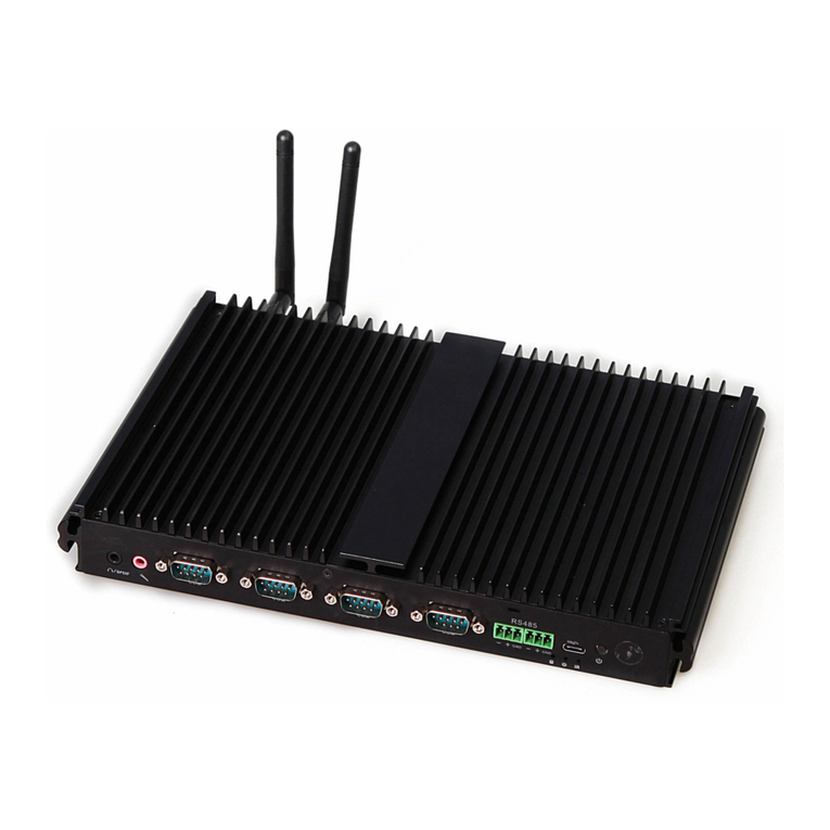
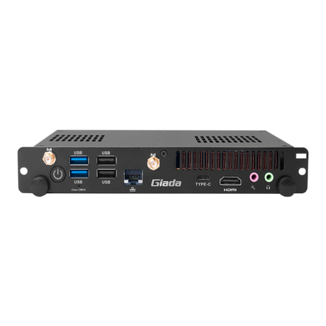
Giada D68 Series User manual


Statement
The copyright of this manual belongs to Shenzhen JEHE Technology Development Co., Ltd.
(Giada, JEHE’s global brand) and all rights are reserved. The company reserves the right to
change this manual at any time without notification. Specifications here are for reference only,
please take the real product as standard.
Without official authorization of Giada, other company or individual may not copy, plagiarize,
translate or disseminate this manual for commercial purpose.
The information provided in this manual is accurate and reliable. The company does not take
any legal responsibility for the consequences of infringement use of this manual.
Safety Notice
• Read the user manual carefully before setting up the Giada product.
• Disconnect the power cord before installing the internal components
• Most electronic components are sensitive to static electrical charge, please wear a
wrist-grounding strap when installing the internal components.
• Don’t disconnect the power cord when the system is running to avoid damage to the
sensitive components by instantaneous surge voltage.
Contact Information
Shenzhen JEHE Technology Development Co., Ltd.
Website: www.giadatech.com
Phone: +86-755-3330 0336
Email: support@giadatech.com
Address: 1~3/F, Block A, Tsinghua Information Harbor, North Section, Shenzhen Hi-tech
Park, Nanshan District, Shenzhen, China
- 1 -
Table of Contents
1. Product Introduction ...................................................................................... 3
2. Interface Description and Hardware Specifications .................................... 3
2.1 Interface Description .................................................................................. 4
2.2 Hardware Specifications ............................................................................. 5
3. Accessories Installation Steps ......................................................................... 6
3.1 Memory Installation ..................................................................................... 7
3.2 MSATA/WiFi/3G/4G Installation ................................................................ 8
3.3 SSD(M.2) Installation .................................................................................. 8
3.4 WIFI(M.2) Installation ................................................................................. 9
3.5 SIM Card Installation ................................................................................... 9
4. BIOS Setup ..................................................................................................... 11
4.1 Main (Standard CMOS) Setup .................................................................. 14
4.2 Advanced BIOS Setup ............................................................................... 15
4.2.1 ACPI Setup ....................................................................................... 15
4.2.2 CPU Configuration ........................................................................... 16
4.2.3 Graphics Configuration .................................................................... 18
4.2.4 Trusted Computing ........................................................................... 19
4.2.5 CSM Configuration .......................................................................... 20

- 2 -
4.2.6 HM Monitor and Smart Fan .............................................................. 22
4.2.7 OEM configuration ........................................................................... 24
4.2.8 System Devices Configuration .......................................................... 25
4.3 Security Setup ............................................................................................. 26
4.4 Booting ........................................................................................................ 27
4.5 Save & Exit ................................................................................................. 29
5. JAHC Introduction ......................................................................................... 30
5.1 Auto Power on ............................................................................................ 30
5.2 JAHC Software ........................................................................................... 32
5.2.1 JAHC Software Functions ................................................................. 32
5.2.2 JAHC Software Installation Guide ................................................... 32
5.2.3 Startup and Shutdown Time Setup .................................................... 35
5.3 Watchdog API and Instruction ................................................................... 37

- 3 -
1. Product Introduction
Based on Intel®Whiskey Lake platform, Giada D68 adopts DDR4 dual-channel memory as well as
M.2 and mSATA storage interface design. With one DP and two HDMI display outputs, it supports
4K resolution. The player is suitable to be applied in high-end digital signage applications.
2. Interface Description and Hardware Specifications
2.1 Interface Description
Front I/O Port
Rear I/O Port

- 4 -
Left I/O Port
Right I/O port
2.2 Hardware Specifications
D68
D68-N1-8145U40M0G
D68-N1-8265U40M0G
Processor
CPU
Intel®Core i3-8145U
Intel®Core i5-8265U
Frequency
1.60 GHz (Up to 3.90 GHz)
2.10 GHz (Up to 3.90 GHz)
BIOS
AMI Source Code
Chipset
SOC
Memory
Type
DDR4-2400MHz
Socket
2 x SO-DIMM
Max Capacity
32 GB
Graphics
GPU
Intel®UHD Graphics 620
Graphic Engine
Direct3D 2015, OpenGL 4.5, OpenCL 2.1
DP
1 x DP (Max.4096 x 2304@60Hz)
HDMI2.0
1 x HDMI (Max.4096 x 2304@60Hz)
HDMI1.4
1 x HDMI (Max.4096 x 2304@24Hz)
Network
Controller
Realtek RTL8111H Gigabit Ethernet
Interface
1 x RJ45

- 5 -
I/O Interface
USB
5 x USB 3.1
Serial Port
1 x RS232
Audio
1 x MIC-IN, 1 x AUDIO-OUT
M.2 (2230)
1 x M.2 (2230) for WiFi
SIM
1 x SIM Slot
Mini PCIe
1 x Full-size Mini-PCIe for mSATA/WiFi/3G/4G
Storage
mSATA
1 x Full-size mSATA (Optional)
M.2
1 x M.2 (2242/2280) for SSD
JAHC
JAHC
Watchdog / Auto power on/IR Remote Control / RTC/Wake On Lan
Operation
System
OS
Windows 10(64-bit) / Linux
Power
Power Type
DC-IN
Input Voltage
19V/3.42A
Mechanical
Construction
Metal
Mounting
Desk/VESA Mounting(JZ183)
Dimension
(W x D x H)
189.6mm x 148.3mm x 26mm
Color
Black
Environment
Operating
Temperature
0-40℃at 0.7m/s Air Flow
Relative Humidity
95%@40℃(non-condensing)
Certification
EMC
CE/FCC

- 6 -
3. Accessories Installation Steps
For safety reasons, please ensure that the power cord is disconnected before opening the case.
How to open the top cover and bottom cover
Unscrew the four screws and remove the top cover. (SO-DIMM #1, mini PCIE slot for
MSATA/WIFI/3G/4G, M.2 for SSD and SIM card slot are on top side)
Unscrew the four screws, push the bottom cover and remove it. (SO-DIMM#2 and M.2 for wifi are
on bottom side)

- 7 -
3.1 Memory Installation
This product only supports DDR4 SO-DIMM memory modules.
1. Locate the SO-DIMM slot on the board.
2. Gently insert the module into the slot in a 45-degree angle.
3. Carefully push down the memory module until it snaps into the locking mechanism.

- 8 -
3.2 MSATA/WIFI/3G/4G Installation
MSATA Installation
1. Plug the MSATA module into the mini PCIE slot.
2. Secure the module to the carrier by tightening up the screw.
WIFI Installation
1. Tighten the WIFI module and WIFI module bracket with screws.
2. Plug the WIFI module into the mini PCIE slot.
3. Secure the module to the carrier by tightening up the screw.
4. Connect the black cable to Main and grey cable to AUX. Install the antenna.
3G/4G Installation
Default SMA connector and cable is for WIFI. Please change to 3G/4G SMA connector and cable.
1. Plug the 3G/4G module into the mini PCIE slot.
2. Secure the module to the carrier by tightening up the screw.
3. Connect the cable to Main and install the antenna.

- 9 -
3.3 SSD (M.2) Installation
1. Plug the SSD (M.2) into the appropriate slot.
2. Secure the module to the carrier by tightening up the screw.
3.4 WIFI (M.2) Installation
1. Plug the WIFI module into the appropriate slot.
2. Secure the module to the carrier by tightening up the screw.
3. Connect the black cable to Main and grey cable to AUX. Install the antenna.

- 10 -
3.5 SIM Card Installation
This product supports standard SIM card with the size of 25mm × 15mm.
1. [Open] the SIM card holder and pull it up.
2. Insert the SIM card.
3. [Lock] the card holder.

- 11 -
4. Bios Setup
Notice:
The descriptions relating to BIOS setup in this Manual is for reference only since the BIOS version
of the product might be upgraded.Giada provides no guarantee that all the contents in this Manual
are consistent with the information you acquired.
BIOS is a basic I/O control program saved in the Flash Memory. Bridging the motherboard and the
operation system, BIOS is used for managing the setup of the related parameters between them.
When the computer is activated, the system is first controlled by the BIOS program. Firstly, a
self-detection called POST is performed to check all hard devices and confirm the parameters of the
synchronous hardware.
Once all detections are completed, BIOS will hand over the controlling to the operation system (OS).
As BIOS serves as the only channel that connects the hardware and software, whether your computer
can run stably and work in optimized state will hinge on how to properly set the parameters in BIOS.
Therefore, the correct setup of BIOS plays a key role in stably running the system and optimizing its
performance.
The CMOS Setup will save the set parameters in the built-in CMOS SRAM on the motherboard.
When the power is shut off, the lithium battery on the motherboard will provide continuously power
to CMOS SRAM.
The BIOS setup program will allow you to configure the following items:
1. HD drive and peripheral devices
2. Video display type and display items
3. Password protection
4. Power management characteristics
A. State of BIOS Setup
When the computer is started up, BIOS will run the self-detection (Post) program. This program includes
series of diagnosis fixed in BIOS. When this program is executed, the following information will appear if
any error is found:
Press [F1] to Run General help
Press [F2] to Load previous values and continue
To enter BIOS, you can press F2; to load the default values and enter the system, you can press DEL to enter
the BIOS interface if no error is found. If the indicative information disappears before you operate, you can
shut off the computer and turn it on again, or you can press the RESET key on the product case. To restart
your computer, you can also simultaneously press < Ctrl > + < Alt > + < Delete >.

- 12 -
B. Function Keys definitions
Hot Key
Description
↑
(Up key) Move to the previous item
↓
(Down key) Move to the next item
←
(Left key) Move to the left item
→
(Right key) Move to the right item
ESC
Exit the current interface
Page Up
Change the setup state, or add the values
Page Down
Change the setup state, or deduct the values
F1
Display the information of the current function Keys definitions.
F9
Load the optimized values
F10
Save the settings and exit the CMOS SETUP
C. Auxiliary information Main interface
When the system enters the main interface of Setup, the major selected contents will be displayed at
the lower part of the interface with the change of the options.
When you set the value for each column, you can view the preset value of the column and the values
that can be set if you press F2, for example, the BIOS default values or CMOS Setup values.
To exit the interface for auxiliary information, press [ESC].
1) Main menu
When the system enters the CMOS Setup menu, you can see the main menu on the upper part of the screen, as
shown in Figure1.
In this main menu, you can use the left and right direction keys to select the setup items.
Once the item is selected, the lower part of the computer screen will show the details of setting.

- 13 -
Fig 1
1) Main (standard CMOS setup)
This item is used for setting the date and time.
2) Advanced (advanced BIOS setup)
This item is used for setting the advanced functions provided by BIOS, such as specifications of PCIe
facilities,CPU, HDD, etc.
3) Security (set the administrator/user password)
4) Boot (startup configuration characteristics)
5) Save & Exit (option of exit)
This item includes load optimal defaults / load failsafe defaults value / discard changes / discard changes and exit.

- 14 -
4.1 Main (Standard CMOS Setup)
1) System time (hh:mm:ss)
Use this item to set the time for the computer, with the format as “HH / MM / SS”.
2) System date (mm:dd:yy)
Use this item to set the date for the computer, with the format as “week, MM / DD / YY”.

- 15 -
4.2 Advanced (Advanced BIOS Setup)
4.2.1 ACPI Setting

- 16 -
ACPI Options
Description
ACPI Sleep state
You can use the ACPI Sleep state option to control system hibernation
Suspend Disabled: Disable system Suspend.
S3 (Suspend to RAM): Enable S3(Suspend to RAM)
State After G3
State After G3 means after restore power supply.
S5 State (Default): If set it as S5 State, it means the system will remain
shutdown state
S0 State: If set it as S0 State, it means the system will be power on
automatically.
Last State: If set it as Last State, it means the system will keep State of
last setup.
Wake system from S5
Disabled: By default, the functions is disabled.
Fixed Time: You can use the fixed Time menu to modify the wake time.
Dynamic Time: You can set multithreaded to wake system from S5 after
enabling Dynamic Time.
4.2.2 CPU Configuration

- 17 -
The menu
Description
CPU Configuration
Boot performance mode
Max Non-Turbo Performance: the best performance.
Max Battery.
Turbo performance.
Intel (VMX) Virtualization Technology
Intel Virtualization Technology is enabled by default. User
can enable and disable the Intel Virtualization Technology
function.
Intel(R)SpeedStep(tm)
Intel(
R)SpeedStep Technology dynamically increases the
processor's frequency as needed by taking advantage of
thermal and power headroom to give you a burst of speed
when you need it, or increased energy efficiency.The option
is enabled by default. You can disable the function if it’s
necessary.
Race To Halt(RTH)
The Race To Halt(
RTH)function is enable by default. It can
adjust the CPU base frequency work in C-state.
Optional: C-state.
Intel(R)Speed Shift Technology
Intel speed shift function is enabled by default. Intel®Speed
Shift Technology uses hardware-controlled P-states to
deliver dramatically quicker responsiveness with
single-threaded, transient (short duration) workloads, such as
web browsing, by allowing the processor to more quickly
select its best operating frequency and voltage for optimal
performance and power efficiency.
Hyper-Threading
Intel Hyper-Threading technology is enabled by default. Intel®
Hyper-Threading Technology (Intel®HT Technology) delivers
two processing threads per physical core. Highly threaded
applications can get more work done in parallel, completing
tasks sooner.
C states
The C-State function is disabled by default.
Turbo Mode
Disabled.
Enabled.

- 18 -
4.2.3 Graphics Configuration
Options
Description
Graphics Configuration
Primary Display
Primary Display options include Auto, IGFX, PEG, PCI, SG mode
and The Primary Display is Auto mode by default.
Auto: It means the discrete graphics is primary display.
IGFX: It means the Intel's integrated graphics is primary
display.
PEG: If Primary Display as PEG mode, it means the discrete
graphics is primary display.
PCI: If Primary Display as PCI mode, it means the signal
output from PCI interface.
SG: If Primary Display as SG mode, it means that both Intel's
integrated graphics and discrete graphics can output signal.
Internal Graphics
It includes Auto, Disabled and Enabled options.
Auto: Internal Graphics is enabled by default.
Disabled.
Enabled.
This manual suits for next models
2
Table of contents
Other Giada Desktop manuals

Giada
Giada F105D User manual

Giada
Giada Mini PC User manual

Giada
Giada F300 Series User manual

Giada
Giada D310 User manual

Giada
Giada f101 Series User manual

Giada
Giada N10U User manual

Giada
Giada F110D Series User manual

Giada
Giada PC612 User manual

Giada
Giada F110D Series User manual

Giada
Giada F100 series User manual