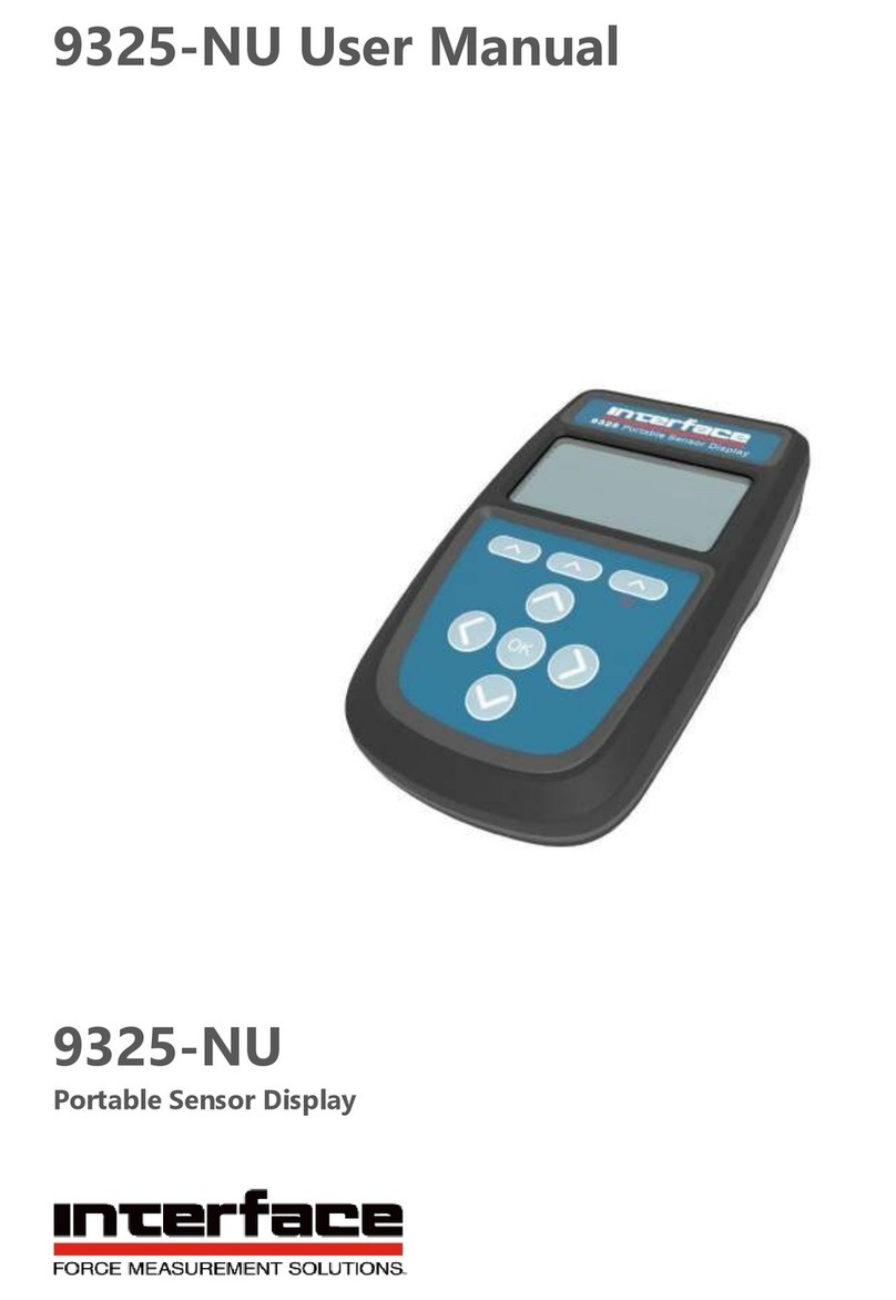
Interface 9325 User manual

9325 Quick Start Guide
Quick Start Guide
9325

The 9325 allows for simple display of strain bridge based measurements such as load cells and
pressure gauges with sensitivity up to +/-480 mV/V.
Up to six calibration ranges are available allowing for different loading modes (tension and
compression) or different sensors. Each calibration range will remember settings that contribute to
the user experience such as selected units and tare values.
TEDS devices using templates 33, 40 and 41 can be connected and will update the viewed
calibration. The last twenty TEDS devices connected will be remembered and recognized when
connected again, reverting to the last user experience settings for that device. TEDS can be disabled
and the internal calibration ranges become available again.
There are also up to six display modes available. These determine what is visible on the LCD
display and what actions are available from the set of three soft keys.
Full configuration is available with a free PC based toolkit. Some simple configuration such as two
point calibration is available from within the handheld, using the menu system.
Introduction / Overview
Interface Inc. www.interfaceforce.com
1
9325 Quick Start Guide 15-403

This document is designed to give a very quick overview of the 9325 and its general, standard
functionality. For more details, see the full manual.
Getting Started
Hardware Overview
Icons
Battery low and other
warning icons.
Primary Display
Main values with
description and units.
Soft Keys
Current Soft key
Function.
Soft Keys
Perform the function
shown on the screen.
Up/Down
Function Depends
on display state.
1. Move through
Calibration
ranges if
available.
2. Move selection
Up/Down in
menu system.
3. Change values
Up/Down of
selected digit
when setting
limits etc.
Left/Right
Function Dependent on display state.
1. Move through display modes if available.
2. Hold for two seconds to move decimal place
Left/Right.
3. Change selected digit when setting limits etc.
Info
Range name etc.
Secondary Display
Can be set to display
other values such as
Max with description
and units.
Tertiary Display
Can be set to display
other values such as
Min with description
and units.
Power
Can Hold for two seconds
to power up/Down.
OK
Function dependent on
display state.
1. Open Menu System
if available.
2. Select menu items.
3. Confirm changes.
4. Long press cancels
changes.
Interface Inc. www.interfaceforce.com
2
9325 Quick Start Guide 15-403

Back
1/4 UNC
For mounting.
Fixing Holes
No. 2 self tapping.
Battery Cover
Secured by single
screw at bottom.
Use 2xAA Batteries.
USB Cover
Micro USB connector
for connection to PC
for configuration and
alternate power
supply.
Interface Inc. www.interfaceforce.com
3
9325 Quick Start Guide 15-403

The Load Cell connector fitted to the 9325 Standard Product is BINDER 770-8. The cable
fitted mating connector is a BINDER 771 8-way male connector. There are three versions
available with different field cable diameters.
Top
Field Cable Diameter
(mm)
Binder Order Code MEL Stock Code
2.5 to 4.0 99 0771 000 08 Not Stocked
4.0 to 6.0 99 0771 001 08 427-739
6.0 to 8.0 99 0771 002 08 427-741
Recommended cable BELDEN 9504 4-pair cable. Max cable size 0.25 mm² , AWG 24. List of
conductor identification and functions
Cable Pair Suggested Color Connector
Pin
Function
1 White 1 Bridge Sensor Reference +SEN
Black 2 Bridge Sensor Reference -SEN
2 Green 3 Bridge Sensor Signal +SIG
Black 4 Bridge Sensor Signal -SIG
3 Red 5 Bridge Sensor Excitation +EXC
Black 6 Bridge Sensor Excitation -EXC
4 Blue 7 TEDS
Black 8 Ground
Shield/Screen Grey Cable screen should only be
connected to chassis of the sensor.
If this cannot be achieved, then it
should be connected to Excitation -
View from solder side of the connector.
Interface Inc. www.interfaceforce.com
4
9325 Quick Start Guide 15-403

Quick, limited setup is possible using just the handheld and no toolkit. To access all the configuration
features, you will need to use the toolkit.
Setting Up Without The Toolkit
Please note, that this must be done in the correct order for the calibration to work correctly.
Changing the Sensitivity after inputting mV/V readings will cause the calibration to be void. Always
make sure you finish with Apply.
Calibration
Press OK to enter the Menu
Use the Up/Down Arrow to navigate to "Calibration". Press OK to confirm.
Use the Up/Down Arrow to navigate to "User Calibration". Press OK to confirm.
1.
2.
3.
Press OK to "Enter Password", if a password is set (Otherwise skip to the next step).
4.
Use the Up/Down Arrow to scroll through available characters.
Use the Left/Right Arrow to move between digits.
Use the Up/Down Arrow to navigate to "Live Calibration". Press OK to confirm.
5.
Use the Up/Down Arrow to navigate to "Sensitivity". Press OK to confirm.
6.
Use the Up/Down Arrow to select the input sensitivity range.Press OK to confirm.
7.
Note: Input sensitivity MUST be selected before proceeding to the next step..
Interface Inc. www.interfaceforce.com
5
9325 Quick Start Guide 15-403

Press the Left Soft Key to return to the previous menu.
Use the Up/Down Arrow to navigate to "Units". Press OK to confirm.
8.
9.
Use the Up/Down Arrow to select calibration Units.Press OK to confirm.
10.
Press the Left Soft Key to return to the previous menu.
11.
Use the Up/Down Arrow to navigate to "Low/High Calibration".
Press OK to confirm.
12.
Use the Up/Down Arrow to navigate to "Set Output Low".Press OK to confirm.
13.
Use the Up/Down Arrow to scroll through available characters.
Use the Left/Right Arrow to move between digits.
Manually enter the Low output required:
Use the Left Soft Key to change the sign of the entered number.
Use the Center Soft Key to move the decimal place to the Left.
Use the Right Soft Key to move the decimal place to the Right.
Interface Inc. www.interfaceforce.com
6
9325 Quick Start Guide 15-403

Use the Up/Down Arrow to navigate to "Set Output High".Press OK to confirm.
14.
Manually enter the High output required (Using the keys as in the previous step):
Press OK to save the changes once the Low output has been entered. (A
long press will cancel the changes and returns to previous view).
Press OK to save the changes once the High output has been entered. (A
long press will cancel the changes and return to previous view).
Use the Up/Down Arrow to navigate to "Capture mV/V Low". Apply the Low Load and let the
load settle.
Once the load has settled press OK to capture mV/V Low.
15.
Note: You can manually edit the mV/V to a value from a calibration certificate here.
Press OK to save the changes. (A long press will cancel the changes
and return to previous view).
Use the Up/Down Arrow to navigate to "Capture mV/V High". Apply the High Load and let
the load settle.
Once the load has settled press OK to capture mV/V High.
16.
Note: You can manually edit the mV/V to a value from a calibration certificate here.
Press OK to save the changes. (A long press will cancel the changes
and return to previous view).
17.Press the Left Soft Key to return to the previous menu.
18.Use the Up/Down Arrow to navigate to "Apply".Press OK to confirm.
Interface Inc. www.interfaceforce.com
7
9325 Quick Start Guide 15-403

19.Return to previous selected display mode.
The Right Soft Key scrolls through the available units for the selected calibration in all
standard display modes.
Change Units
A long press of the Left/Right Keys will shift the decimal place position for the selected
units in all standard display modes.
Change Decimal Places
Please note, the values saved for the thresholds are applied in the calibrated units of the currently
selected range. This means that different ranges will trigger at different loads if the calibrated unit is
different.
Overload / Underload Alarm Settings
Press OK to enter the Menu
Use the Up/Down Arrow to navigate to "Alarm". Press OK to confirm.
1.
2.
Use the Up/Down Arrow to navigate to "Alarm Source". Press OK to confirm.
3.
Use the Up/Down Arrow to navigate to "Gross" or "Net".Press OK to confirm.
4.
Press the Left Soft Key to return to the previous menu.
5.
Use the Up/Down Arrow to navigate to "Alarm Mode".Press OK to confirm.
6.
Interface Inc. www.interfaceforce.com
8
9325 Quick Start Guide 15-403

Use the Up/Down Arrow to navigate to "Normal" or "Latched".Press OK to confirm.
7.
Use the Up/Down Arrow to navigate to "Alarm Thresholds". Press OK to confirm.
8.
Use the Up/Down Arrow to navigate to "Alarm Low". Press OK to confirm.
9.
Use the Up/Down Arrow to scroll through available characters.
Use the Left/Right Arrow to move between digits.
Manually enter the Low Threshold required:
Use the Left Soft Key to change the sign of the entered number.
Use the Center Soft Key to move the decimal place to the Left.
Use the Right Soft Key to move the decimal place to the Right.
Press OK to save the changes once the Low Threshold has been entered. (A
long press will cancel the changes and returns to previous view).
Use the Up/Down Arrow to navigate to "Alarm High". Press OK to confirm.
10.
Manually enter the High Threshold required (Using the keys as in the previous step):
Press OK to save the changes once the High Threshold has been
entered. (A long press will cancel the changes and return to previous view).
Interface Inc. www.interfaceforce.com
9
9325 Quick Start Guide 15-403

11. Press the Left Soft Key to return to the previous menu.
Use the Up/Down Arrow to navigate to "Alarm Trigger". Press OK to confirm.
12.
Use the Up/Down Arrow to select from the following trigger options:
Disabled
Outside Limits (<low, >high)
Inside Limits (>low, <high)
Above high (>high)
Below high (<high)
Above low (>low)
Below low (<low)
Press OK to confirm once a trigger option has been selected.
13. Press the Left Soft Key to return to the previous menu.
Use the Up/Down Arrow to navigate to "Alarm Action". Press OK to confirm.
14.
Use the Up/Down Arrow to select from the following action options:
None
Beep
Flash
Both
Press OK to confirm once a trigger option has been selected.
15. Press the Left Soft Key to return to the previous menu.
19.Return to previous selected display mode.
Interface Inc. www.interfaceforce.com
10
9325 Quick Start Guide 15-403

Plug in a TEDS enabled load cell:
Using TEDS
Press OK to confirm.
1. The Message " New TEDS Device Use Session Defaults" will be displayed.
Note: TEDS tables will automatically be loaded.
Use the Up/Down Arrow to change selected TEDS calibration.
Use the Up/Down Arrow to change displayed units.
To disable TEDS and use the 9325’s internal calibration use the following steps:
Press OK to enter the Menu
Use the Up/Down Arrow to navigate to "Calibration". Press OK to confirm.
1.
2.
Use the Up/Down Arrow to navigate to "User Calibration". Press OK to confirm.
3.
4.Press OK to "Enter Password", if a password is set (Otherwise skip to the next step).
Use the Up/Down Arrow to scroll through available characters.
Use the Left/Right Arrow to move between digits.
Use the Up/Down Arrow to navigate to "TEDS". Press OK to confirm.
5.
Interface Inc. www.interfaceforce.com
11
9325 Quick Start Guide 15-403

6. Use the Up/Down Arrow to navigate to "TEDS Mode".Press OK to confirm.
Use the Up/Down Arrow to select from the following TEDS mode options:
Enabled
Disabled
Press OK to confirm once a TEDS mode option has been selected.
Press the Left Soft Key to return to the previous menu.
7.
Press the Right Soft Key to return to the previous selected display mode.
8.
Press OK to confirm.
Note: The next time that you connect that TEDS device, following message will be displayed:
"Known TEDS Device Session Restored"
Interface Inc. www.interfaceforce.com
12
9325 Quick Start Guide 15-403

More complex setup is possible using the supplied toolkit software. Install the toolkit onto your
windows PC and connect the USB to the 9325, then open the toolkit:
Toolkit Overview
1. Select the correct device
2. Click Connect
Navigation is achieved using the icons along the top of the toolkit:
Alarms
Set Alarm
Thresholds and
actions
Calibration
6 different calibration
ranges available
Logging
Graph and
logging of
selected
calibration
Settings
Set display and key
functions
Home
Disconnect and return to
connection page
Measurement
Shows current readings, set update
rate and quality, set resolution, zero
mask, scale steady, system zero etc.
Configuration
Customize the 9325
to only enable
needed functions.
Import & Export
Backup and restore
all settings including
option to clone.
Information
Backup About the
current connected 9325
For further information, please see the 9325 User Manual.
Interface Inc. www.interfaceforce.com
13
9325 Quick Start Guide 15-403
Other manuals for 9325
2
Table of contents
Other Interface Monitor manuals
Popular Monitor manuals by other brands
Panasonic
Panasonic TH-42PF30U operating instructions

LG
LG 27MN60T-W.AUS owner's manual

NEC
NEC XP21 - MultiSync - 21" CRT Display user manual

Fujitsu
Fujitsu SCALEOVIEW C17-7 user manual
Samsung
Samsung SyncMaster P2770FH Manual Del Usuario
Atlantis Land
Atlantis Land I-See S150 LCD Monitor A05-15AM-C01 specification
