Interklima PCE 03 User manual

CASSETTE FAN COIL
COOLING/HEATING
TERMINAL UNIT
COOLING CAPACITY: 2,5 kW - 10,5 kW
HEATING CAPACITY: 5,7 kW - 17,2 KW
Features
Stylish.
Compact and lightweight.
Ideal for standardized false ceilings.
Low noise.
Variable air flow distribution patterns.
Infrared remote control. (standard) or wired controller availability.
aster-Slave control capability.
RS-485 Port, for B S communication.
Built-in condensate pump.
Easy access to all the components for maintenance
Standard filter for clean air.
Fresh air and branch ducting capability.
Self diagnosis.
Interklima Hydronic Cassette Fan Coils are the
ideal solution for cooling/heating applications.
They are available in eight models with
nominal capacities ranging from 2 5kW to
10 5 kW in cooling and 5 7kW up to 17 2kW
in heating.
This series is ideal in combination with
Interklima air cooled water chillers or heat
pumps for air conditioning offices shops or
any other commercial application where floor
and wall space is needed for fittings and
furniture by being installed flush into every
ceilling with various air flow pattern flexibility
according to the room shape and layout.
PCE 03-04-06-08-09-10-12-16

NO ENCLATURE
1 Interklima Hydronic cassette
2 Model numbers
03=2kW
04=3kW
06=4kW
08=6kW
09=6,5kW
10=7,5kW
12=9kW
16=10,5kW
3 Type
V- 2 pipe P- 4 pipe
4 Electrical Characteristic
S- 230V 1ph / 50Hz

Interklima Terminal nits
PCE -VS ñ Hydronic cassette 3
1. Technical Specifications
2. Capacity Tables
- Cooling
- Heating
3. Outlook Drawings
4. Wiring Diagrams
5. Installation
6. Controller
Instruction and Specifications
7. Service
Contents

Interklima Terminal nits
PCE -VS ñ Hydronic cassette
4
Technical specifications1.
PCE -03
Single
7.5
6.6
5.6
2.5
2.25
2.1
2.03
1.79
1.67
5.7
5.15
4.8
3
2.71
2.52
30/35/38
33.5
0.149
0.34
480
7.0
1.3
570
570
250
31
Model
Numbers of fan blowers
Nomimal airflow
Nominal cooling capacity*
Nominal sensible
cooling capacity*
Nominal eating capacity**
Nominal sensible
eating capacity**
Noise level@1M (L/M/H)
Power supply (V/P /Hz)
Fan motor power
Fan motor running current
Fan motor starting current
Operation control & t ermostat
Water flow rate
Water pressure drop
Water content
Cond. drain connection I.D.
Casing dimentions
Panel dimentions
Cross weig t
Connection met od
Water Connection
PCE -04
Single
8.5
7
5.8
3
2.6
2.21
2.17
1.92
1.67
6
5.45
4.7
3.3
2.84
2.5
30/36/39
36.7
0.168
0.438
587
10.2
1.3
570
570
250
31
PCE -06
Single
10.4
9.4
7.8
4
3.4
2.9
2.84
2.51
2.19
6.9
6
5.2
4.2
3.65
3.17
35/41/43
54.2
0.241
0.759
765
9.6
1.79
570
570
290
33
PCE -08
Single
12.8
10.4
8.6
5
4.2
3.52
3.17
2.84
2.47
9
7.6
6.52
5.2
4.4
3.8
37/43/46
70.7
0.32
0.886
940
13.9
1.79
570
570
290
33
PCE -09
Twin
17
14
11.5
6.5
5.67
4.8
4.7
4.04
3.48
11.5
10
8.6
7.2
6.22
5.36
34/39/40
33.5x2
0.149x2
0.876
1.265
22.5
1.47
1.100
570
290
57
PCE -10
Twin
19.3
16
13
7.5
6.48
5.34
5.2
4.48
3.9
13
11.3
9.7
8.3
7.18
6.17
36/40/43
54.2x2
0.241x2
1.518
1.450
24.9
2.84
1.100
570
290
57
PCE -12
Twin
21.4
18.5
15.5
9
7.6
6.4
5.38
4.73
4.2
14.6
12.5
11.1
9.9
8.5
7.6
38/45/49
60.2x2
0.315x2
1.518
1.500
12.3
2.84
1.100
570
290
57
PCE -16
Twin
25
21
17.5
10.5
9
7.5
6.3
5.6
4.92
17.2
15.04
13.2
11
9.76
8.6
40/47/50
70.7x2
0.32x2
1.77
1.770
15.4
2.84
1.100
570
290
57
H
M
L
H
M
L
H
M
L
H
M
L
H
M
L
L
W
D
In
Out
kW
kW
kW
kW
kW
kW
kW
kW
kW
kW
kW
kW
kW
kW
kW
dB(A)
Watt
Amp
Amp
L/h
KPa
L
mm(in)
mm
mm
mm
mm
kgs
mm(in)
mm(in)
230/1/50
Remote control handset & wired wall pad
19.05(3/4)
Socket (threaded female)
19.05 (3/4)
19.05 (3/4)
PCE-VS
NOTES
All capacities are based on: cooling: indoor 27oC DB 19.5oC WB outdoor: 35oC DB 24oC WB
heating: indoor 20oC DB outdoor: 7oC DB 6oC WB

Interklima Terminal nits
PCE -VS ñ Hydronic cassette 5
Capacity Tables2.
Qw 1/h
502
593
670
387
425
476
306
353
400
240
264
302
189
208
236
Pf kW
2.33
2.75
3.10
1.63
1.88
2.12
1.31
1.51
1.71
1.00
1.11
1.19
0.75
0.81
0.86
Pfs kW
1.70
2.00
2.21
1.43
1.67
1.90
1.28
1.47
1.67
0.98
1.09
1.17
0.74
0.79
0.84
Tad
9.9
10.3
10.9
12.7
12.8
12.9
13.8
14.1
14.3
16.4
16.4
17.4
18.5
19.1
19.6
Taw
9.9
10.1
10.3
12.7
12.8
12.9
13.7
13.8
13.9
14.7
14.9
15.1
15.5
15.7
15.9
Pf kW
2.53
3.01
3.41
1.82
2.12
2.39
1.53
1.76
1.99
1.20
1.34
1.47
0.92
1.00
1.11
Pfs kW
1.82
2.16
2.38
1.53
1.82
2.07
1.45
1.68
1.9
1.18
1.31
1.44
0.90
0.97
1.09
Tad
10.7
11.1
11.7
13.2
13.5
13.6
14.4
14.5
14.8
16.6
17.2
17.7
19.1
19.7
19.9
Taw
10.7
10.9
11.0
13.2
13.5
13.6
14.4
14.5
14.6
15.4
15.6
15.8
16.3
16.5
16.6
Pf kW
2.66
3.14
3.55
2.05
2.25
2.52
1.62
1.87
2.12
1.27
1.40
1.60
1.00
1.10
1.25
Pfs kW
1.80
2.09
2.30
1.58
1.79
2.03
1.41
1.64
1.79
1.24
1.34
1.53
0.97
1.07
1.23
Tad
10.9
11.5
12.2
13.4
13.8
13.9
14.7
14.8
15.5
16.2
16.9
17.2
18.4
19.0
19.2
Taw
10.9
11.1
11.3
13.4
13.8
13.9
14.7
14.8
14.9
15.8
16.0
16.1
16.6
16.8
16.9
Pf kW
3.05
3.61
4.11
2.43
2.74
3.06
2.04
2.32
2.61
1.60
1.81
2.01
1.26
1.40
1.56
Pfs kW
1.95
2.30
2.51
1.74
1.98
2.16
1.54
1.75
1.93
1.33
1.40
1.68
1.22
1.35
1.52
Tad
11.6
12.0
12.8
14.1
14.3
15.0
15.5
15.9
16.6
17.2
17.8
18.1
18.2
18.8
19.3
Taw
11.6
11.8
11.9
14.1
14.3
14.5
15.2
15.4
15.6
16.5
16.7
16.9
17.5
17.7
17.9
Dpw kPa
7.69
10.4
12.9
4.81
5.70
6.97
3.15
4.08
5.11
2.03
2.42
3.08
1.32
1.57
1.97
Qa[m3/h]
323
391
452
340
398
453
336
396
458
338
393
462
337
397
469
PCE-03
Twi
5
7
9
11
13
TAI DB25-WB17.8 TAI DB27-WB19 TAI DB27-WB19.5 TAI DB29-WB21.1
Cooling
PCE-03
Qw1/h
540
644
755
417
491
587
323
378
446
253
287
327
208
232
259
Pf kW
2.48
2.94
3.48
1.95
2.29
2.71
1.45
1.70
2.00
1.05
1.19
1.38
0.87
0.95
1.05
Pfs kW
1.82
2.11
2.35
1.60
1.83
2.09
1.40
1.61
1.83
1.03
1.17
1.34
0.85
0.93
1.02
Tad
10.1
10.6
11.6
11.9
12.4
13.0
13.5
13.9
14.5
16.4
16.9
17.2
18.0
18.5
19.1
Taw
10.1
10.2
10.3
11.9
12.0
12.1
13.5
13.6
13.7
14.7
14.9
15.0
15.3
15.5
15.7
Pf kW
2.75
3.29
3.89
2.17
2.56
3.06
1.67
1.96
2.32
1.27
1.45
1.69
1.07
1.20
1.34
Pfs kW
1.98
2.31
2.60
1.74
2.00
2.29
1.54
1.79
2.05
1.24
1.41
1.64
1.04
1.17
1.31
Tad
10.7
11.3
12.2
12.6
13.1
13.9
14.2
14.6
15.2
16.6
17.2
17.5
18.3
18.8
19.4
Taw
10.7
10.8
10.9
12.6
12.7
12.8
14.2
14.3
14.4
15.4
15.6
15.7
16.0
16.2
16.4
Pf kW
2.86
3.41
4.00
2.21
2.60
3.11
1.71
2.00
2.36
1.34
1.52
1.73
1.10
1.23
1.37
Pfs kW
1.94
2.19
2.50
1.67
1.92
2.17
1.48
1.73
1.96
1.30
1.48
1.68
1.07
1.19
1.34
Tad
11.0
12.0
12.7
13.1
13.6
14.5
14.7
15.0
15.7
16.2
16.7
17.3
18.1
18.7
19.2
Taw
11.0
11.1
11.3
13.1
13.2
13.3
14.7
14.8
14.9
15.8
16.0
16.2
16.5
16.7
16.9
Pf kW
3.26
3.91
4.59
2.62
3.10
3.68
2.00
2.37
2.80
1.59
1.82
2.08
1.30
1.47
1.65
Pfs kW
2.09
2.41
2.71
1.84
2.10
2.38
1.60
1.87
2.11
1.45
1.63
1.86
1.24
1.40
1.57
Tad
11.7
12.5
13.5
13.8
14.5
15.3
15.6
16.0
16.8
16.9
17.6
18.2
18.6
19.2
19.8
Taw
11.7
11.8
12.0
13.8
13.9
14.0
15.6
15.7
15.8
16.8
17.0
17.2
17.6
17.8
18.0
DpwkPa
8.76
12.0
16.0
5.51
7.38
10.2
3.47
4.60
6.20
2.24
2.81
3.54
1.57
1.92
2.33
Qa[m3/h]
352
425
510
351
420
510
354
423
510
356
427
514
358
429
514
PCE-04
Twi
5
7
9
11
13
TAI DB25-WB17.8 TAI DB27-WB19 TAI DB27-WB19.5 TAI DB29-WB21.1
PCE-04
NOTES
TAI: Air in temperature Pf: Total cooling capacity
TWI: Fluid in temperature Pfs: Sensible cooling capacity
Qw: Fluid flow rate in heat exchanger tad: Discharge air dry bulb temperature
Dpw: Pressure drop standard coil Taw: Discharge air wet bulb temperature
Qa: Air flow
Design and specification are subject to change without prior notice for product improvement

Interklima Terminal nits
PCE -VS ñ Hydronic cassette
6
Qw1/h
816
974
1146
665
793
940
506
591
695
329
385
449
251
291
336
Pf kW
3.80
4.51
5.30
3.01
3.59
4.25
2.20
2.61
3.07
1.44
1.69
1.96
1.10
1.27
1.46
Pfs kW
2.62
2.97
3.36
2.3
2.64
2.98
2.03
2.3
2.61
1.41
1.65
1.9
1.07
1.23
1.43
Tad
10.4
11.2
12.0
12.0
12.7
13.4
13.5
14.2
14.8
16.9
17.2
17.5
18.8
19.1
19.3
Taw
9.7
9.8
10.0
11.5
11.6
11.7
13.3
13.4
13.5
14.9
15.0
15.1
15.6
15.7
15.8
Pf kW
4.20
5.02
5.96
3.41
4.06
4.83
2.59
3.06
3.55
1.70
2.00
2.33
1.25
1.45
1.67
Pfs kW
2.85
3.25
3.66
2.55
2.90
3.26
2.24
2.55
2.88
1.68
1.96
2.30
1.23
1.42
1.63
Tad
11.0
11.9
12.8
12.6
13.4
14.3
14.3
15.0
15.7
17.4
17.7
17.9
19.9
20.2
20.5
Taw
10.3
10.4
10.5
12.1
12.2
12.3
13.9
14.0
14.2
15.7
15.8
15.9
16.6
16.7
16.8
Pf kW
4.32
5.16
6.07
3.52
4.20
4.98
2.68
3.13
3.68
1.74
2.04
2.38
1.33
1.54
1.78
Pfs kW
2.78
3.15
3.58
2.47
2.84
3.17
2.16
2.46
2.77
1.69
2.00
2.33
1.30
1.50
1.73
Tad
11.4
12.3
13.1
13.0
13.7
14.6
14.7
15.4
16.1
17.3
17.5
17.8
19.5
19.8
20.1
Taw
10.7
10.8
11.0
12.5
12.6
12.7
14.3
14.5
14.6
16.2
16.3
16.4
17.0
17.1
17.2
Pf kW
5.00
5.93
7.05
4.10
4.88
5.80
3.18
3.72
4.40
2.15
2.54
2.98
1.73
2.02
2.35
Pfs kW
3.02
3.42
3.82
2.68
3.06
3.42
2.35
2.68
3.02
2.03
2.33
2.62
1.68
1.90
2.13
Tad
12.0
13.0
14.1
13.8
14.6
15.6
15.6
16.3
17.1
17.3
17.9
18.6
19.3
19.9
20.5
Taw
11.2
11.4
11.5
13.2
13.3
13.4
15.1
15.3
15.4
17.1
17.2
17.3
17.9
18.0
18.1
DpwkPa
10.79
14.83
19.88
7.46
10.25
13.92
4.56
6.04
8.08
2.10
2.79
3.68
1.29
1.69
2.18
Qa[m3/h]
516
624
750
516
624
750
516
626
751
517
625
752
518
624
752
PCE-08
Twi
5
7
9
11
13
TAI DB25-WB17.8 TAI DB27-WB19 TAI DB27-WB19.5 TAI DB29-WB21.1
PCE-08
Qw1/h
1100
1300
1550
906
1070
1265
695
827
972
493
585
672
429
506
576
Pf kW
5.13
6.16
7.41
4.12
4.92
5.80
3.02
3.68
4.37
2.07
2.45
2.86
1.75
2.05
2.38
Pfs kW
3.69
4.37
4.95
3.26
3.83
4.39
2.80
3.32
3.85
2.02
2.38
2.76
1.71
2.00
2.31
Tad
9.6
10.0
11.0
11.4
11.8
12.5
13.2
13.5
14.0
16.4
16.7
17.0
17.7
18.0
18.3
Taw
9.6
9.7
9.8
11.4
11.5
11.7
13.2
13.2
13.3
14.7
14.8
14.9
15.2
15.3
15.4
Pf kW
5.71
6.85
8.15
4.65
5.56
6.60
3.53
4.21
5.03
2.56
3.04
3.56
2.16
2.55
2.98
Pfs kW
4.03
4.77
5.47
3.58
4.15
4.81
3.12
3.73
4.26
2.52
2.98
3.48
2.11
2.54
2.92
Tad
10.2
10.6
11.5
12.0
12.6
13.3
13.8
14.0
14.8
16.3
16.6
16.9
18.0
18.1
18.5
Taw
10.2
10.3
10.5
12.0
12.1
12.3
13.8
13.9
14.0
15.3
15.4
15.5
15.9
16.0
16.1
Pf kW
5.80
6.90
8.20
4.80
5.67
6.70
3.68
4.38
5.15
2.61
3.10
3.56
2.27
2.68
3.05
Pfs kW
3.90
4.58
5.27
3.48
4.04
4.70
3.04
3.59
4.10
2.54
3.03
3.57
2.22
2.53
2.97
Tad
10.7
11.2
12.0
12.4
13.0
13.6
14.2
14.5
15.3
16.2
16.4
16.7
17.5
18.1
18.4
Taw
10.7
10.9
11.1
12.4
12.6
12.8
14.2
14.3
14.5
15.8
15.9
16.1
16.3
16.4
16.6
Pf kW
6.85
8.16
9.71
5.63
6.70
8.00
4.40
5.28
6.30
3.10
3.78
4.37
2.47
2.90
3.42
Pfs kW
4.31
5.01
5.68
3.80
4.47
5.05
3.32
3.96
4.51
2.85
3.45
3.89
2.38
2.82
3.30
Tad
11.0
11.7
12.8
13.0
13.5
14.5
14.9
15.2
16.0
16.8
16.9
17.7
18.8
19.0
19.4
Taw
11.0
11.2
11.4
13.0
13.2
13.3
14.9
15.0
15.1
16.8
16.8
17.0
17.7
17.8
17.9
DpwkPa
17.3
23.7
32.3
12.3
16.6
22.5
7.64
10.5
14.0
4.1
5.6
7.2
3.2
4.3
5.45
Qa[m3/h]
691
840
1022
694
841
1022
695
843
1029
694
846
1028
695
846
1027
PCE-09
Twi
5
7
9
11
13
TAI DB25-WB17.8 TAI DB27-WB19 TAI DB27-WB19.5 TAI DB29-WB21.1
PCE-09
NOTES
TAI: Air in temperature Pf: Total cooling capacity
TWI: Fluid in temperature Pfs: Sensible cooling capacity
Qw: Fluid flow rate in heat exchanger tad: Discharge air dry bulb temperature
Dpw: Pressure drop standard coil Taw: Discharge air wet bulb temperature
Qa: Air flow
Design and specification are subject to change without prior notice for product improvement

Interklima Terminal nits
PCE -VS ñ Hydronic cassette 7
Qw1/h
1227
1472
1755
1010
1223
1450
793
961
1148
527
631
746
425
504
569
Pf kW
5.80
6.97
8.28
4.64
5.61
6.74
3.48
4.20
5.01
2.19
2.60
3.06
1.52
1.78
2.06
Pfs kW
4.19
4.76
5.45
3.64
4.19
4.83
3.19
3.69
4.29
2.15
2.53
2.97
1.49
1.74
2.00
Tad
9.7
10.7
11.5
11.5
12.3
13.0
13.1
13.8
14.3
16.9
17.2
17.5
19.3
19.6
19.9
Taw
9.7
9.8
10.0
11.4
11.5
11.6
13.1
13.2
13.3
14.9
15.0
15.1
15.8
15.9
16.0
Pf kW
6.42
7.73
9.21
5.24
6.35
7.54
4.06
4.90
5.86
2.73
3.27
3.87
2.15
2.57
2.96
Pfs kW
4.54
5.20
5.96
4.03
4.64
5.34
3.55
4.13
4.70
2.67
3.18
3.80
2.10
2.45
2.91
Tad
10.2
11.3
12.2
12.0
12.9
13.7
13.7
14.4
15.2
16.9
17.2
17.4
19.1
19.4
19.6
Taw
10.2
10.4
10.6
12.0
12.1
12.3
13.7
13.8
13.9
15.5
15.6
15.7
16.3
16.4
16.5
Pf kW
6.50
7.80
9.30
5.35
6.48
7.68
4.20
5.09
6.08
2.79
3.34
3.95
2.25
2.67
3.01
Pfs kW
4.38
5.13
5.84
3.90
4.48
5.20
3.43
4.00
4.58
2.72
3.25
3.84
2.18
2.59
2.94
Tad
10.8
11.5
12.5
12.5
13.4
14.0
14.1
14.8
15.5
16.7
17.0
17.3
18.7
19.0
19.5
Taw
10.8
11.0
11.2
12.5
12.6
12.8
14.1
14.2
14.3
16.0
16.1
16.2
16.7
16.8
17.0
Pf kW
7.65
9.21
11.03
6.37
7.63
9.18
4.99
6.03
7.20
3.43
4.12
4.90
2.78
3.32
3.8
Pfs kW
4.74
5.44
6.18
4.26
4.86
5.59
3.76
4.35
4.95
3.20
3.73
4.30
2.73
3.16
3.57
Tad
11.4
12.5
13.6
13.3
14.2
15.0
14.9
15.7
16.5
16.9
17.5
18.1
18.6
19.2
19.9
Taw
11.1
11.3
11.5
13.1
13.2
13.3
14.9
15.0
15.1
16.9
17.0
17.1
17.7
17.8
18.0
DpwkPa
21.3
29.5
40.5
15.0
21.2
24.9
9.7
13.7
18.9
4.64
6.4
8.7
3.2
4.3
5.3
Qa[m3/h]
783
961
1172
783
963
1172
781
963
1173
783
964
1174
784
964
1173
PCE-10
Twi
5
7
9
11
13
TAI DB25-WB17.8 TAI DB27-WB19 TAI DB27-WB19.5 TAI DB29-WB21.1
PCE-10
Qw1/h
1365
1610
1912
1089
1280
1510
814
952
1108
593
685
784
487
561
631
Pf kW
6.29
7.41
8.90
4.96
5.82
6.84
3.56
4.15
4.91
2.52
2.90
3.27
1.90
2.16
2.38
Pfs kW
4.47
5.05
5.72
3.93
4.42
5.04
3.47
3.91
4.41
2.46
2.81
3.19
1.84
2.16
2.32
Tad
11.1
11.8
12.7
12.7
13.4
14.1
14.1
14.7
15.4
17.2
17.5
18.0
19.1
19.3
19.9
Taw
10.4
10.5
10.6
12.1
12.2
12.4
13.8
13.9
14.0
15.0
15.1
15.3
15.7
15.8
16.0
Pf kW
7.03
8.30
9.95
5.60
6.55
7.73
4.15
4.83
5.62
3.08
3.56
4.08
2.53
2.91
3.27
Pfs kW
4.84
5.51
6.25
4.31
4.93
5.52
3.87
4.33
4.9
3.02
3.48
3.92
2.47
2.83
3.21
Tad
11.9
12.6
13.5
13.5
14.0
15.0
14.8
15.5
16.3
17.4
17.7
18.4
19.1
19.4
19.9
Taw
11.0
11.1
11.2
12.8
12.9
13.1
14.5
14.6
14.8
15.7
15.8
16.0
16.3
16.4
16.6
Pf kW
7.23
8.53
10.13
5.77
6.78
8.00
4.31
5.04
5.87
3.14
3.63
4.15
2.58
2.97
3.34
Pfs kW
4.70
5.33
6.05
4.20
4.73
5.38
3.70
4.19
4.76
3.05
3.56
4.05
2.50
2.91
3.26
Tad
12.3
13.0
13.9
13.8
14.5
15.3
15.3
15.9
16.6
17.3
17.5
18.1
19.0
19.2
19.8
Taw
11.4
11.5
11.7
13.2
13.3
13.5
14.9
15.0
15.2
16.2
16.3
16.5
16.8
16.9
17.1
Pf kW
8.30
9.78
11.65
6.70
7.90
9.45
5.11
5.98
7.00
3.70
4.30
4.95
3.12
3.60
4.10
Pfs kW
5.04
5.77
6.54
4.53
5.14
5.86
4.01
4.51
5.15
3.51
3.96
4.54
2.90
3.23
3.70
Tad
13.2
13.8
14.8
14.7
15.4
16.2
16.3
17.0
17.7
17.8
18.4
19.0
19.7
20.3
20.8
Taw
12.1
12.2
12.4
14.0
14.1
14.2
15.8
15.9
16.1
17.3
17.4
17.6
17.9
18.0
18.2
DpwkPa
10.30
13.90
18.90
6.90
9.20
12.40
4.10
5.40
7.10
2.30
2.99
3.80
1.60
2.10
2.60
Qa[m3/h]
930
1111
1352
931
1111
1353
932
1112
1354
933
1112
1354
932
1113
1354
PCE-12
Twi
5
7
9
11
13
TAI DB25-WB17.8 TAI DB27-WB19 TAI DB27-WB19.5 TAI DB29-WB21.1
PCE-12
NOTES
TAI: Air in temperature Pf: Total cooling capacity
TWI: Fluid in temperature Pfs: Sensible cooling capacity
Qw: Fluid flow rate in heat exchanger tad: Discharge air dry bulb temperature
Dpw: Pressure drop standard coil Taw: Discharge air wet bulb temperature
Qa: Air flow
Design and specification are subject to change without prior notice for product improvement

Interklima Terminal nits
PCE -VS ñ Hydronic cassette
8
Qw1/h
1544
1831
2128
1231
1456
1707
900
1057
1231
633
733
818
553
638
702
Pf kW
7.10
8.40
9.76
5.61
6.61
7.73
4.02
4.70
5.46
2.45
2.82
3.22
2.05
2.34
2.64
Pfs kW
5.19
5.90
6.67
4.63
5.24
5.91
3.92
4.60
5.17
2.37
2.76
3.14
2.01
2.29
2.57
Tad
10.7
11.4
12.1
12.2
12.9
13.5
14.1
14.3
14.9
18.3
18.5
18.8
19.3
19.6
19.9
Taw
10.4
10.5
10.7
12.1
12.2
12.3
13.8
13.9
14.0
15.4
15.5
15.6
15.8
15.9
16.0
Pf kW
7.94
9.41
10.93
6.31
7.40
8.75
4.58
5.38
6.25
3.17
3.68
4.23
2.76
3.19
3.65
Pfs kW
5.72
6.46
7.21
5.04
5.78
6.47
4.44
5.07
5.70
3.08
3.61
4.14
2.69
3.09
3.58
Tad
11.2
12.1
13.0
13.0
13.5
14.4
14.6
15.2
15.8
18.3
18.5
18.8
19.4
19.7
19.9
Taw
11.0
11.1
11.3
12.8
12.9
13.0
14.6
14.7
14.8
16.0
16.1
16.2
16.4
16.5
16.6
Pf kW
8.18
9.70
11.27
6.52
7.71
9.04
4.77
5.60
6.52
3.35
3.88
4.33
2.93
3.38
3.72
Pfs kW
5.57
6.28
7.05
4.92
5.60
6.30
4.29
4.93
5.50
3.27
3.78
4.20
2.84
3.31
3.63
Tad
11.6
12.5
13.3
13.3
14.0
14.7
15.0
15.5
16.2
17.8
18.1
18.7
19.0
19.2
19.8
Taw
11.4
11.5
11.7
13.2
13.3
13.4
15.0
15.1
15.2
16.4
16.5
16.7
16.8
16.9
17.1
Pf kW
9.35
11.09
12.93
7.55
8.94
10.5
5.65
6.65
7.78
3.86
4.50
5.20
3.30
3.82
4.23
Pfs kW
5.61
6.32
7.00
4.93
5.60
6.31
4.37
4.89
5.57
3.83
4.40
4.90
3.20
3.71
4.10
Tad
13.4
14.3
15.3
15.2
15.9
16.6
16.7
17.5
18.0
18.2
18.7
19.3
19.9
20.2
20.8
Taw
12.1
12.2
12.4
14.0
14.1
14.2
15.9
16.0
16.1
17.6
17.7
17.8
18.1
18.2
18.4
DpwkPa
12.9
17.5
23.0
8.6
11.6
15.4
4.9
6.5
8.6
2.6
3.37
4.1
2.03
2.63
3.1
Qa[m3/h]
1050
1262
1502
1051
1262
1504
1052
1262
1503
1058
1265
1510
1059
1267
1508
PCE-16
Twi
5
7
9
11
13
TAI DB25-WB17.8 TAI DB27-WB19 TAI DB27-WB19.5 TAI DB29-WB21.1
PCE-16
NOTES
TAI: Air in temperature Pf: Total cooling capacity
TWI: Fluid in temperature Pfs: Sensible cooling capacity
Qw: Fluid flow rate in heat exchanger tad: Discharge air dry bulb temperature
Dpw: Pressure drop standard coil Taw: Discharge air wet bulb temperature
Qa: Air flow
Design and specification are subject to change without prior notice for product improvement
Qw 1/h
105
122
133
183
211
236
267
314
346
351
413
449
Pf kW
1.46
1.72
1.87
2.51
2.96
3.26
3.58
4.24
4.66
4.65
5.51
6.00
Tad
32.0
31.4
30.6
42.0
41.0
40.0
52.1
51.0
49.5
62.3
61.0
58.5
Pf kW
1.35
1.56
1.71
2.35
2.71
3.03
3.42
4.03
4.44
4.50
5.31
5.76
Tad
32.9
32.2
31.5
42.5
41.2
40.4
52.6
51.5
50.0
62.7
61.6
58.8
Pf kW
1.20
1.40
1.53
2.23
2.58
2.85
3.28
3.81
4.26
4.31
5.10
5.59
Tad
33.5
33.0
32.3
43.3
42.2
41.2
53.4
51.7
50.8
63.4
61.5
59.7
Pf kW
1.06
1.24
1.37
2.07
2.40
2.67
3.11
3.64
4.05
4.15
4.88
5.35
Tad
34.2
33.7
33.2
43.8
42.7
42.0
53.9
52.3
51.3
63.9
62.0
60.2
DpwkPa
0.410
0.530
0.627
1.110
1.440
1.760
2.180
2.930
3.500
3.580
4.800
5.580
Qa[m3/h]
323
395
459
323
395
459
324
395
458
326
394
458
PCE-03
Twi
40
50
60
70
TAI 18 TAI 20 TAI 22 TAI 24
Heating
PCE-03
NOTES
TAI: Air in temperature Pf: Total cooling capacity
TWI: Fluid in temperature tad: Discharge air dry bulb temperature
Qw: Fluid flow rate in heat exchanger
Dpw: Pressure drop standard coil
Qa: Air flow
Design and specification are subject to change without prior notice for product improvement

Interklima Terminal nits
PCE -VS ñ Hydronic cassette 9
Qw 1/h
109.0
128.0
145.0
195.0
221.3
256.5
286.0
328.0
376.0
366.0
425.0
482.0
Pf kW
1.55
1.78
2.03
2.69
3.07
3.50
3.85
4.41
5.06
4.91
5.71
6.54
Tad
31.5
30.9
30.3
41.4
40.3
39.1
51.6
50.0
48.5
60.9
59.5
57.5
Pf kW
1.40
1.64
1.86
2.50
2.84
3.29
3.67
4.20
4.82
4.70
5.45
6.18
Tad
32.2
31.9
31.2
41.8
40.7
39.8
52.0
50.5
49.0
61.0
59.7
57.2
Pf kW
1.28
1.46
1.64
2.36
2.68
3.03
3.50
3.98
4.53
4.54
5.29
5.93
Tad
33.1
32.6
31.9
42.4
41.5
40.3
52.4
50.9
49.3
61.6
60.3
57.8
Pf kW
1.14
1.31
1.46
2.20
2.52
2.84
3.32
3.80
4.31
4.42
5.11
5.75
Tad
34.0
33.5
32.8
43.2
42.3
41.1
53.1
51.6
50.1
62.4
61.1
58.6
DpwkPa
0.44
0.58
0.73
1.24
1.56
2.04
2.50
3.16
4.05
3.97
5.05
6.34
Qa[m3/h]
355.0
425.0
513.0
354.0
424.0
513.5
354.0
425.0
513.6
354.0
424.0
513.4
PCE-04
Twi
40
50
60
70
TAI 18 TAI 20 TAI 22 TAI 24
PCE-04
Qw 1/h
140
161
184
252
291
334
366
425
486
483
556
640
Pf kW
1.97
2.27
2.60
3.46
3.98
4.57
4.94
5.71
6.54
6.43
7.40
8.54
Tad
31.2
30.5
29.7
41.0
39.9
38.7
50.9
49.2
47.6
60.7
58.6
56.4
Pf kW
1.79
2.06
2.36
3.24
3.73
4.29
4.70
5.45
6.24
6.20
7.13
8.21
Tad
31.9
31.3
30.7
41.6
40.5
39.4
51.4
49.6
48.2
61.0
59.0
57.0
Pf kW
1.620
1.855
2.126
3.020
3.490
3.970
4.460
5.155
5.930
5.930
6.840
7.900
Tad
32.7
32.2
31.6
42.2
41.1
40.4
51.8
50.3
48.8
61.5
59.6
57.5
Pf kW
1.435
1.650
1.890
2.810
3.230
3.680
4.230
4.890
5.630
5.680
6.570
7.560
Tad
33.6
33.1
32.5
42.7
41.8
41.1
52.2
50.8
49.3
61.9
59.9
58.1
DpwkPa
0.386
0.497
0.634
1.120
1.450
1.860
2.190
2.860
3.650
3.610
4.600
6.000
Qa[m3/h]
465
563
682
464
562
683
463
568
684
467
565
686
PCE-06
Twi
40
50
60
70
TAI 18 TAI 20 TAI 22 TAI 24
PCE-06
Qw 1/h
159
183
216
288
331
391
417
481
570
546
635
753
Pf kW
2.24
2.58
3.05
3.93
4.54
5.37
5.62
6.49
7.70
7.31
8.45
10.05
Tad
31.6
30.9
30.5
41.8
40.5
40.1
52.0
50.3
49.6
62.1
60.1
59.1
Pf kW
2.04
2.35
2.77
3.69
4.25
5.02
5.35
6.18
7.32
7.01
8.15
9.66
Tad
32.3
31.7
31.4
42.3
41.1
40.6
52.2
50.7
50.0
62.3
60.3
59.5
Pf kW
1.84
2.11
2.49
3.44
3.97
4.70
5.09
5.88
6.97
6.75
7.81
9.28
Tad
33.1
32.5
32.3
42.8
41.8
41.3
52.7
51.2
50.6
62.8
60.9
60.1
Pf kW
1.63
1.88
2.22
3.19
3.69
4.36
4.82
5.57
6.6
6.47
7.48
8.89
Tad
33.9
33.4
33.1
43.3
42.3
41.9
53.1
51.7
51.1
63.1
61.3
60.5
DpwkPa
0.488
0.630
0.847
1.420
1.830
2.470
2.770
3.590
4.870
4.510
5.910
8.020
Qa[m3/h]
513
621
751
511
622
753
513
622
754
512
625
756
PCE-08
Twi
40
50
60
70
TAI 18 TAI 20 TAI 22 TAI 24
PCE-08
NOTES
TAI: Air in temperature Qw: Fluid flow rate in heat exchanger Qa: Air flow Pf: Total cooling capacity
TWI: Fluid in temperature Dpw: Pressure drop standard coil tad: Discharge air dry bulb temperature
Design and specification are subject to change without prior notice for product improvement

Interklima Terminal nits
PCE -VS ñ Hydronic cassette
10
Qw 1/h
232
270
312
409
475
549
591
686
790
768
895
1028
Pf kW
3.29
3.82
4.39
5.60
6.52
7.53
7.95
9.20
10.62
10.30
11.95
13.79
Tad
32.7
32.0
31.3
43.0
41.9
40.8
53.4
51.8
50.1
63.9
61.9
59.7
Pf kW
2.98
3.46
4.00
5.25
6.10
7.05
7.59
8.80
10.14
9.85
11.48
13.20
Tad
33.3
32.7
32.1
43.5
42.4
41.3
53.9
52.3
50.6
64.0
62.0
59.9
Pf kW
2.69
3.11
3.57
4.92
5.71
6.59
7.21
8.35
9.59
9.51
11.03
12.73
Tad
34.0
33.4
32.8
44.0
43.0
41.9
54.2
52.7
51.0
64.5
62.5
60.5
Pf kW
2.39
2.77
3.17
4.57
5.30
6.12
6.82
7.92
9.12
9.10
10.57
12.20
Tad
34.7
34.2
33.6
44.4
43.5
42.5
54.5
53.1
51.5
64.7
62.8
60.9
DpwkPa
0.914
1.200
1.550
2.530
3.320
4.310
4.920
6.420
8.300
7.870
10.400
13.300
Qa[m3/h]
692
842
1022
690
841
1023
692
842
1024
692
845
1022
PCE-09
Twi
40
50
60
70
TAI 18 TAI 20 TAI 22 TAI 24
PCE-09
Qw 1/h
256
298
343
452
526
608
650
757
875
848
988
1142
Pf kW
3.62
4.21
4.84
6.19
7.21
8.32
8.75
10.21
11.78
11.32
13.18
15.26
Tad
32.3
31.5
30.78
42.4
41.2
39.9
52.6
50.8
49.1
62.7
60.4
58.2
Pf kW
3.29
3.83
44.00
5.80
6.75
7.80
8.34
9.72
11.23
10.98
12.68
14.66
Tad
33.0
32.3
31.6
42.9
41.7
40.6
53.0
51.2
49.6
63.0
60.8
58.7
Pf kW
2.96
3.45
3.97
5.41
6.31
7.28
7.92
9.23
10.67
10.44
12.18
14.07
Tad
33.7
33.1
32.5
43.4
42.3
41.2
53.3
51.7
50.1
63.3
61.2
59.1
Pf kW
2.63
3.06
3.53
5.03
5.87
6.76
7.50
8.74
10.10
10.00
11.67
13.47
Tad
34.4
33.8
33.3
43.9
42.7
41.8
53.7
52.1
50.6
63.6
61.5
59.6
DpwkPa
1.09
1.44
1.84
3.03
3.98
5.17
5.83
7.68
9.96
9.41
12.30
16.10
Qa[m3/h]
782
962
1172
783
962
1170
781
963
1172
782
960
1171
PCE-10
Twi
40
50
60
70
TAI 18 TAI 20 TAI 22 TAI 24
PCE-10
NOTES
TAI: Air in temperature Qw: Fluid flow rate in heat exchanger Qa: Air flow Pf: Total cooling capacity
TWI: Fluid in temperature Dpw: Pressure drop standard coil tad: Discharge air dry bulb temperature
Design and specification are subject to change without prior notice for product improvement

Interklima Terminal nits
PCE -VS ñ Hydronic cassette 11
Qw 1/h
275
310
358
496
562
648
717
815
943
943
1064
1239
Pf kW
3.87
4.39
5.04
6.77
7.70
8.86
9.68
10.96
12.70
12.60
14.28
16.50
Tad
30.8
30.3
29.5
40.4
39.5
38.2
50.0
48.7
47.0
59.7
57.9
55.7
Pf kW
3.53
3.98
4.59
6.37
7.21
8.32
9.20
10.46
12.10
12.10
13.65
15.90
Tad
31.7
31.1
30.5
41.1
40.2
39.0
50.5
49.3
47.6
60.0
58.2
56.3
Pf kW
3.18
3.57
4.12
5.94
6.72
7.76
8.75
9.92
11.48
11.63
13.10
15.25
Tad
32.5
32.0
31.4
41.6
40.8
39.7
51.0
49.8
48.2
60.5
58.7
56.8
Pf kW
2.81
3.18
3.67
5.52
6.25
7.19
8.32
9.42
10.88
11.15
12.60
14.62
Tad
33.3
32.9
32.4
42.3
41.5
40.4
51.5
50.4
48.8
61.0
59.3
57.4
DpwkPa
0.497
0.620
0.800
1.440
1.800
2.330
2.790
3.510
4.570
4.570
5.670
7.450
Qa[m3/h]
932
1108
1351
933
1103
1353
932
1103
1354
935
1104
1354
PCE-12
Twi
40
50
60
70
TAI 18 TAI 20 TAI 22 TAI 24
PCE-12
Qw 1/h
300
341
383
542
616
694
786
898
1013
1029
1172
1332
Pf kW
4.23
4.82
5.40
7.42
8.41
9.53
10.59
12.06
13.61
13.74
15.70
17.70
Tad
30.4
29.8
29.1
39.8
38.6
37.6
49.1
47.5
46.0
58.3
56.4
54.4
Pf kW
3.85
4.38
4.91
6.95
7.90
8.90
10.08
11.52
13.00
13.2
15.04
17.10
Tad
31.3
30.7
30.1
40.4
39.3
38.3
49.6
48.2
46.7
58.8
56.8
55.1
Pf kW
3.47
3.92
4.43
6.48
7.35
8.32
9.57
10.94
12.35
12.72
14.48
16.40
Tad
32.2
31.6
31.1
41.0
40.0
39.1
50.1
48.8
47.4
59.4
57.4
55.7
Pf kW
3.07
3.51
3.94
6.03
6.85
7.73
9.08
10.36
11.71
12.18
13.90
15.70
Tad
33.0
32.6
32.1
41.7
40.8
39.9
50.6
49.4
48.1
59.8
58.0
56.3
DpwkPa
0.58
0.73
0.90
1.68
2.12
2.63
3.29
4.18
5.19
5.34
6.75
8.51
Qa[m3/h]
1053
1265
1502
1053
1265
1503
1052
1262
1505
1051
1263
1505
PCE-16
Twi
40
50
60
70
TAI 18 TAI 20 TAI 22 TAI 24
PCE-16
NOTES
TAI: Air in temperature Qw: Fluid flow rate in heat exchanger Qa: Air flow Pf: Total cooling capacity
TWI: Fluid in temperature Dpw: Pressure drop standard coil tad: Discharge air dry bulb temperature
Design and specification are subject to change without prior notice for product improvement
Interklima Terminal nits
PCE -VS ñ Hydronic cassette
12
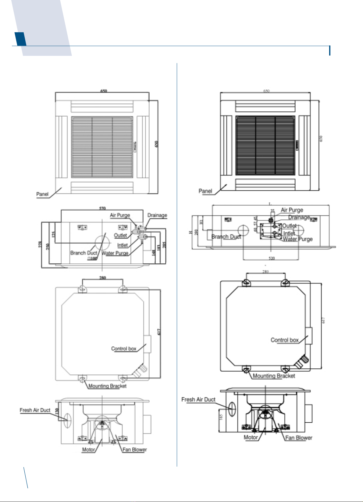
Outlook drawings3.
PCE-03/04-VS PCE-06/08-VS

Interklima Terminal nits
PCE -VS ñ Hydronic cassette 13
PCE-09/10/12/16-VS

Interklima Terminal nits
PCE -VS ñ Hydronic cassette
14
Wiring Diagrams4.
Control and power supply wiring diagram PCE-03/04/06/08
NOTES
Wirring diagrams on unit take precidents.

Interklima Terminal nits
PCE -VS ñ Hydronic cassette 15
Control and power supply wiring diagram PCE-09/10/12/16
NOTES
Wirring diagrams on unit take precidents.
aster - Slave control wiring diagram

Factory supplied accessories
Check to ensure all factory supplied accessories are supplied with
the unit.
The appliance should be installed in accordance with
national wiring regulation.
Safety considerations
ñ When working on air conditioning equipment observe
precautions in this manual and on plates and tables attached
to the unit. Follow all safety codes and other safety
precautions that may apply.
ñ Installing and servicing air conditioning equipment should be
done by trained and qualified service personnel only.
Untrained personnel can perform only basic maintenance
functions such as cleaning coils filters and replacing filters.
ñ Ensure that the electrical supply and frequency are adequate
for the operating current required for this specific installation.
Warning
Before any service or maintenance operations turn off the main
power switch.
ñ The manufacturer denies any responsibility and warranty shall
be void if these installation instructions are not observed.
ñ Never switch off the power main supply when unit is operating
in the cooling cycle.
To switch off the fan coil unit use only the ON-OFF button.
ñ This avoids over-flow in the drain pan by allowing the pump
to drain any condensate water due to regulating valve losses
when chiller is working.
Operation limits
ñ Power supply
ñ Water circuit
- Minimum entering water temperature: +2ÆC
- Maximum entering water temperature: +80ÆC
- Water side maximum pressure: 1400 kPa (142 m.w.c)
Before installation
The installation site must be established by the system designer
or other qualified professional taking account of the technical
requisites and current standards and legislation.
PCE fan coils must be installed by an authorized company only.
PCE fan coils are designed for installation in a false ceiling for
intake of fresh air from outside and for deviation of a small part of
the treated air for discharge in a neighboring room.
They must be installed in such a way as to enable treated air to
circulate throughout the room and in respect of the minimum
distances required for technical maintenance operations.
ñ It is advisable to place the unit close to the installation site
without removing it from the packaging.
Do not put heavy tools or weights on the packaging.
ñ Upon receipt the unit and the packaging must be checked for
damage sustained in transit and if necessary a damage claim
must be filed with the shipping company.
ñ Check immediately for installation accessories inside the
packaging.
ñ Do not lift unit by the condensate drain discharge pipe or by
the water connections; lift it by the four corners.(Fig.1)
ñ Check and note the unit serial number.
Interklima Terminal nits
PCE -VS ñ Hydronic cassette
16
Installation5.
FACTORY SUPPLIED ACCESSORIES AMOUNT
LCD Remote control 1
Mounting Bracket (Already on the unit) 1
Installation manual 1
Batteries 2
External drain pan 1
Volt P ase Hz
230 1 50
fig.1
fig.2
Cover A

Selection location
ñ Do not install the unit in rooms where flammable gas or
alkaline acid substances are present.
Aluminum/copper coils and/or internal plastic components
can be damaged irreparably.
ñ Do not install in workshops or kitchens; oil vapors drawn in by
treated air might deposit on the coils and alter their
performance or damage the internal plastic parts of the unit.
ñ Installation of the unit will be facilitated by using a stacker and
inserting a plywood sheet between the unit and the elevated
stacker.(Fig.2)
ñ It is recommended to position the unit as centrally as possible
in the room to ensure optimum air distribution. (Fig.3)
Generally the best louver position is the one which allows air
diffusion along the ceiling.
Alternatively intermediate positions can be selected.
ñ Check that it is possible to remove panels from ceiling in the
selected position to allow enough clearance for maintenance
and servicing operations.
Installation location
Install the unit in a position:
ñ Having sufficient strength to carry the weight of the unit.
ñ Where the inlet and outlet grilles are not obstructed and the
conditioned air is able to blow all over the room.
ñ From where condensate can be easily run to drain.
ñ Check the distance between the upper slab and false ceiling to
ensure the unit will suit the distance. See Fig.4
ñ Ensure there is sufficient space around the unit to service it.
See Fig.5
Interklima Terminal nits
PCE -VS ñ Hydronic cassette 17
Model A (mm.) B (mm.)
PCE-03/04 250 10 or more
PCE-06/08/09/10/12/16 290 10 or more
fig.3
fig.5
Fig.4

Interklima Terminal nits
PCE -VS ñ Hydronic cassette
18
Installation met od
Cassette Unit
ñ Using the installation template open ceiling panels and install
the suspension bolts as in Fig.6 below
590 x 590: Dimensions for opening
616 x 280: Suspension Bolts
MODELS PCE-03/04/06/08
590 x 1120: Dimensions for opening
517.5 x 1047.5: Suspension Bolts
MODELS PCE-09/10/12/16
Opening Dimensions and Positions for Suspension Bolts
ñ Mark position of suspension rods water lines and
condensate drain pipe power supply cables and remote
control cable.
Supporting rods can be fixed depending on the type of
ceiling as shown in Fig. 7 and Fig.8.
ñ Fit suspension brackets supplied with the unit to the threaded
rods (Fig.9).
Do not tighten nuts and counter nuts; this operation has to
be done only after final leveling of the unit when all the
connections have been completed.
Fig. 6
Fig. 7
Fig.9
Fig. 8

ñ Ensure the ceiling is horizontally level otherwise condensate
water cannot drain.
ñ The casing is fixed to the slab with 4 drop rods. The rods
should have two nuts and washers to lock the unit in position.
The Cassette brackets will then hook over the washers.
ñ When lifting the Cassette into position care should be taken
not to lift the unit by the drip tray which could be damaged.
ñ Lift unit (without the air panel) with care by its four corners
only. Do not lift unit by the condensate drain discharge pipe
or by the piping connections.
ñ Incline unit (Fig.10 Fig.11 Fig.13 Fig.14) and insert it into
the false ceiling. Insert the rods into the bracket slot.
With minimum height (see table) false ceilings it might be
necessary to remove some T brackets of the false ceiling
temporarily.
ñ Using a level guide line up the unit with a spirit level and
keep dimension between the body and the lower part of the
false ceiling (Fig.12 Fig.15).
ñ Line up the unit to the supporting bars of the false ceiling
tightening the nuts and counter nuts of the threaded rods.
ñ After connection of the condensate drain piping and piping
connections check again that the unit is level.
Interklima Terminal nits
PCE -VS ñ Hydronic cassette 19
Fig. 10
Fig.12
Fig. 11
Fig. 13
Fig.15
Fig. 14
MODEL PCE/03/04/06/08
A (mm.) 3
MODEL PCE/09/10/12/16
A (mm.) 3

Interklima Terminal nits
PCE -VS ñ Hydronic cassette
20
ñ The spaces between the unit and ceiling can now be adjusted.
Use the drop rods to make the adjustment.
ñ Check to ensure the unit is level. The drain will then
automatically be lower than the rest of the drip tray.
ñ Tighten the nuts on the suspended rods.
Drain pipe work
Indoor Unit
ñ The unit is fitted with a condensate pump with a 500 mm. lift.
ñ The unit is provided with 22 mm. bore flexible hose 300 mm.
long.
ñ The flexible hose should be fitted into a 22 mm O/S º.
polyvinyl tube and sealed. The drain must be installed with a
downward slope.
ñ On completion the drain line should be insulated
Water connections
ñ Water connections are fixed to the unit body to avoid breaks
when pipes are connected to valve assemblies; it is advisable
to tighten the connection with a spanner.
ñ The upper coil connection is supplied with air purge screw the
lower connection with water purge screw suitable for 8mm.
wrench or screw-driver.
ñ Coil is partially drainable; it is advisable to blow air into the coil
for complete drainage.
Pipe connection kit (Option)
Pipe connection dimensional drawings
PCE-03/04-VS
PCE-06/08-VS
PCE-09/10/12/16-VS
Fig.16
This manual suits for next models
15
Table of contents
Popular Heat Pump manuals by other brands

ACD
ACD CHD09KCH19S owner's manual

Viessmann
Viessmann KWT Vitocal 350-G Pro Series Installation and service instructions

Daikin
Daikin SkyAir RZQ200 250C7Y1B Service manual

Airwell
Airwell CW-AR Installation and maintenance manual

Toshiba
Toshiba ESTIA HWS-802XWHM3-E engineering data

Daikin
Daikin Altherma EBLQ05CAV3 User reference guide

Thermocold
Thermocold MEX VS 15 RH Technical bulletin

Fujitsu
Fujitsu AOYA18LALL Installation and operating manual

Fujitsu
Fujitsu WATERSTAGE WS A050DD6 Series Maintenance Document

Geostar
Geostar Aston Compact Series installation manual

Viessmann
Viessmann VITOCAL 200-G Installation and service instructions for contractors

AXEN
AXEN AXSPS-90 Operation and installation manual


