International Communications Group Sigma7 Instruction Manual

Sigma7Telephone
Handset
User’s Guide and Installation Manual
Manual Number 500114
International Communications Group, Inc.
www.icg.aero
Sigma
7
TelephoneManual
©Copyright 2006 International Communications Group, ICG.
All rights reserved.


International Communications Group, Inc.
www.icg.aero
Printed in the United States of America.
© Copyright 2006 International Communications Group, Inc. All rights reserved.
INTERNATIONAL COMMUNICATIONS GROUP, INC.
Sigma7Telephone Handset
User’s Guide and Installation Manual
This manual includes coverage of the following model part number(s):
500040
500041
500044
500044-1
500066
500905
500905-1
Aviation Telephony Handset
International Communications Group, Inc.
Newport News, VA 23603
Cage Code 088F2

InternationalCommunicationsGroup,Inc.
User’s Guide and Installation Manual
Sigma7
Aviation Telephone Handset
Sigma7
April 2006
Use or disclosure of information on this page is subject to the restrictions in the proprietary notice of this document.
THIS PAGE IS INTENTIONALLY LEFT BLANK.

InternationalCommunications Group,Inc.
User’s Guide and Installation Manual
Sigma7
Aviation Telephone Handset
Sigma7
iii
April 2006
Use or disclosure of information on this page is subject to the restrictions in the proprietary notice of this document.
RECORD OF REVISIONS
REVISION ECN # COMMENTS/DESCRIPTION DATE
REVISED
A---- Initial Release 5/1/02
BECN 1225 Incorporated ECO 1225 8/9/02
CECN 1601 Incorporated ECO 1601 5/12/04
DECN 1702 Incorporated ECO 1702 2/8/05
EECN 1734 Incorporated ECO 1734 3/29/05
FECN 1929 Revised manual and updated format 4/24/06
GECN 2043 Updated reference drawings on pages 22-29 01/24/2006
HECN 2176 Updated matrix on page ix 05/21/2007
Proprietary Notice
This document and the information disclosed herein are proprietary data of the International
Communications Group (ICG), Inc. Neither this document nor the information contained herein
shall be used, reproduced, or disclosed to others without written authorization of ICG, except for
installation of ICG equipment.
Notice–Freedom of Information Act 5-USC 553 and Disclosure of Confidential Information
Generally (18 USC 1905).
ICG is furnishing this document in confidence. The information disclosed herein falls within
exemption (b)(4) of USC 552 and the prohibitions of 18 USC 1905. For further information,
contact the Customer Support representative of ICG, Newport News, VA 23603, or phone
(757) 947-1030 or (800) 279-1991.
Copyright 2006
International Communications Group, Inc.
All rights reserved.

InternationalCommunications Group,Inc.
User’s Guide and Installation Manual
Sigma7
Aviation Telephone Handset
Sigma7
iv
April 2006
Use or disclosure of information on this page is subject to the restrictions in the proprietary notice of this document.
THIS PAGE IS INTENTIONALLY LEFT BLANK.

InternationalCommunications Group,Inc.
User’s Guide and Installation Manual
Sigma7
Aviation Telephone Handset
Sigma7
v
April 2006
Use or disclosure of information on this page is subject to the restrictions in the proprietary notice of this document.
SERVICE BULLETIN LIST
When a Service Bulletin is received for this unit, perform the instructions given, log it into the
Service Bulletin List given below, and insert the Service Bulletin into this section to maintain a
historical record.
SERVICE
BULLETIN NO.
TITLE MANUAL
REVISION NO. MANUAL
REVISION DATE

InternationalCommunications Group,Inc.
User’s Guide and Installation Manual
Sigma7
Aviation Telephone Handset
Sigma7
vi
April 2006
Use or disclosure of information on this page is subject to the restrictions in the proprietary notice of this document.
THIS PAGE IS INTENTIONALLY LEFT BLANK.

InternationalCommunications Group,Inc.
User’s Guide and Installation Manual
Sigma7
Aviation Telephone Handset
Sigma7
vii
April 2006
Use or disclosure of information on this page is subject to the restrictions in the proprietary notice of this document.
Foreword
1. About This Manual
This manual presents the instructions for using and installing the Sigma7telephone handset on
aircraft. For convenience and ease of use, this document is divided into two major sections.
General information is in the User’s Guide that follows the front matter; that information targets the
casual user or cabin personnel. Detailed installation instructions can be found in the Installation
Manual section; that information is geared to installation personnel.
A convenient reference guide to abbreviations, acronyms, and symbols used in the text is in the
Glossary at the back of this document. Specialized terms will generally be written out everywhere in
the text to avoid confusion. Standard, well-known electronic terms and circuit signal names will be
abbreviated in the text without being defined. Also, a fairly comprehensive International Country
Code Directory is at the back of this manual.
Customer Support at ICG welcomes your questions, comments, and corrections about this manual.
In any correspondence, we would appreciate the publication number, equipment designations
(found on the Sigma7handset), document page or figure number, and your comments. Please send
your communication to the following address:
Customer Support
International Communications Group, Inc.
Newport News, VA 23603
2. The Sigma7Handset
The Sigma7telephone is an aeronautical Communications Center handset designed to operate as a
standard and familiar telephone. The Sigma7is similar in operation to an office or residential
telephone. The device accommodates various mounting methods and has features similar to those
found on contemporary telephones. Facilities such as a Liquid Crystal Display (LCD) and built-in
magnetic stripe reader provide convenient operation and support for all types of calling services.
The handset also facilitates data port connectivity for modem or Ethernet as an optional
configuration.

InternationalCommunications Group,Inc.
User’s Guide and Installation Manual
Sigma7
Aviation Telephone Handset
Sigma7
viii
April 2006
Use or disclosure of information on this page is subject to the restrictions in the proprietary notice of this document.
3. Notices, Patches, and Updates
ICG has established on the corporate website (www.icg.aero) an area where clients can register to
receive advance information and notifications about changes to this unit. Clients who participate will
also be able to download patches or future updates as they become available.
To take advantage of this free opportunity, simply fill out the requested information at the ICG
website. You may remove your name from this service at any time by contacting ICG.
Privacy Statement
ICG will not sell, trade, or transfer user addresses or
information to any other sources.
4. Handling Electronics
As with any electronic component, the Sigma7requires care when being handled. Always observe
standard safety precautions to prevent personal injury or damage to the unit.
CAUTION
TURN OFF POWER BEFORE CONNECTING OR
REMOVING ANY COMPONENT TO AVOID
DAMAGING THE ELECTRONICS.
5. Advisories
Stray fingerprints, smudges, wire clippings, or metal shavings on outside surfaces should be
removed with care. If cleaning is necessary, use only mild soap and a dampened cloth to swab the
exterior surface.
Note
Use fluid sparingly to avoid letting any water, cleaners,
or solvents reach the internal components.

InternationalCommunications Group,Inc.
User’s Guide and Installation Manual
Sigma7
Aviation Telephone Handset
Sigma7
ix
April 2006
Use or disclosure of information on this page is subject to the restrictions in the proprietary notice of this document.
This document applies to all dash-number configurations of the Sigma7, P/N 500–.
500040-WX-YZ Telefonix cord reel 58 inches, tall profile
500041-WX-YZ No PCB, sheet metal, no RJ-11 modular plug,
Telefonix cord reel 58 inches
500905-WX-YZ Shallow cradle, Telefonix reel 58 inches
500905-WX-YZ-1MBM cord reel 48 inches, shallow profile
500044-WX-YZ Telefonix cord reel 58 inches, shallow profile,
Pigtail
500044-WX-YZ-1MBM cord reel 48 inches, shallow profile, pigtail
Part Numbers
500066-Z4-wire unit with MBM cord reel 48 inches
W = Cradle 0 = No Cradle (Remote Retractor Reel Mounting)
1 = Long Cradle
2 = Short Cradle (Remote Retractor Reel Mounting)
3 = Low Profile
4 = Modified Cradle for Coiled Cord
X = RJ-11
Data Jack
on cradle
0 = No RJ-11 Data Jack Installed
1 = RJ-11 Data Jack Installed
Y = Cord Reel
Type 0 = Remote-Mount Retractor Reel
1 = Retractor Reel Attached to Cradle
2 = 25-ft. Coil Cord (No Retractor Reel)
3 = 12-ft. Coil Cord (No Retractor Reel)
4 = Remote Reel without Conduit
Z = Color 0 = Black
1 = White
2 = Beige
3 = Gray
= Pantone Number
For example, to specify a Sigma7telephone with normal cradle operation, but mounted in a drink rail
with an RJ-11 data jack in a beige color, the part number would be 500040-11-12.

InternationalCommunications Group,Inc.
User’s Guide and Installation Manual
Sigma7
Aviation Telephone Handset
Sigma7
x
April 2006
Use or disclosure of information on this page is subject to the restrictions in the proprietary notice of this document.
THIS PAGE IS INTENTIONALLY LEFT BLANK.

InternationalCommunications Group,Inc.
User’s Guide and Installation Manual
Sigma7
Aviation Telephone Handset
Sigma7
xi
April 2006
Use or disclosure of information on this page is subject to the restrictions in the proprietary notice of this document.
LIST OF EFFECTIVE PAGES
SUBJECT PAGE DATE SUBJECT PAGE DATE
Record of Revisions iii 4/2006
Description 11 4/2006
iv 4/2006
12 4/2006
Service Bulletin List v4/2006
Installation Procedures 13 4/2006
vi 4/2006
14 4/2006
15 4/2006
Foreword vii 4/2006
16 4/2006
viii 4/2006
17 4/2006
ix 4/2006
18
4/2006
x4/2006
Testing the Unit 19
4/2006
List of Effective Pages xi 4/2006
20
4/2006
xii 4/2006
Fits and Clearances 21
4/2006
Table of Contents xiii 4/2006
22
4/2006
xiv 4/2006
23
4/2006
xv 4/2006
24
4/2006
xvi 4/2006
25
4/2006
26
4/2006
User’s Guide 27
4/2006
28
4/2008
System Overview 1 4/2006
29
4/2006
24/2006
30
4/2006
Basic Use 34/2006
System Specifications 31
4/2006
4 4/2006
32
4/2006
Special Use 54/2006
Special Tools, Fixtures, 33
4/2006
6 4/2006
and Equipment 34
4/2006
Installation Manual Troubleshooting the System 35
4/2006
36
4/2006
Introduction 7 4/2006
84/2006
Wiring Diagrams 37
4/2006
94/0229
38
4/2006
10 4/2006
Air Worthiness/RMA 39
4/2006
40
4/2006

InternationalCommunications Group,Inc.
User’s Guide and Installation Manual
Sigma7
Aviation Telephone Handset
Sigma7
xii
April 2006
Use or disclosure of information on this page is subject to the restrictions in the proprietary notice of this document.
Glossary 41 4/2006
International Country Codes
43
4/2006
42 4/2006
44
4/2006

InternationalCommunications Group,Inc.
User’s Guide and Installation Manual
Sigma7
Aviation Telephone Handset
Sigma7
xiii
April 2006
Use or disclosure of information on this page is subject to the restrictions in the proprietary notice of this document.
TABLE OF CONTENTS
SECTION PAGE
User’s Guide
SYSTEM OVERVIEW.............................................................................................................1
BASIC USE ............................................................................................................................3
1. Making a Call.....................................................................................................................3
2. Answering a call.................................................................................................................3
3. Putting a Call on Hold ........................................................................................................3
4. Adjusting Ear-Piece Volume...............................................................................................3
SPECIAL USE........................................................................................................................5
1.On/Answer...........................................................................................................................5
2.Off .....................................................................................................................................5
3,Flash....................................................................................................................................5
4.Digits 0–9, *, and # ..............................................................................................................5
Installation Manual
INTRODUCTION.....................................................................................................................7
1.General................................................................................................................................7
2. Planning.............................................................................................................................7
(A) Preparation............................................................................................................7
(B) Unpacking .............................................................................................................7
(C) Cleaning................................................................................................................8
3. Abbreviations and Acronyms..............................................................................................8
4. Advisories..........................................................................................................................8
5. Related Documents............................................................................................................9
DESCRIPTION......................................................................................................................11
INSTALLATION PROCEDURES..........................................................................................13
1. Planning...........................................................................................................................13
2. Connections.....................................................................................................................13
(A) Line (J1) ..............................................................................................................13
(B) Phone (J2)...........................................................................................................14
(C) Ringer/Audio (J3).................................................................................................14
3. Wiring ..............................................................................................................................14
4. Mounting the Handset.......................................................................................................15
5. Programming Extension (Seat) Number ...........................................................................16
6. Handset Adjustments.......................................................................................................16
(A) Temporary Adjustments.......................................................................................16
(B) Permanent Adjustments ......................................................................................16
(C) Default Settings...................................................................................................16
(D) Entering Programming Mode...............................................................................17
(E) Service Menu Settings.........................................................................................17

InternationalCommunications Group,Inc.
User’s Guide and Installation Manual
Sigma7
Aviation Telephone Handset
Sigma7
xiv
April 2006
Use or disclosure of information on this page is subject to the restrictions in the proprietary notice of this document.
TESTING THE UNIT.............................................................................................................19
1. Introduction......................................................................................................................19
2. Making an Outbound Call.................................................................................................19
3. Answering an Inbound Call ..............................................................................................19
4. Making a New Call...........................................................................................................19
FITS AND CLEARANCES....................................................................................................21
SYSTEM SPECIFICATIONS.................................................................................................31
1. Purpose ...........................................................................................................................31
2. Product Definition.............................................................................................................31
3. Specifications...................................................................................................................31
(A) 2-Wire Models .....................................................................................................31
(B) 4-Wire Models .....................................................................................................31
SPECIAL TOOLS, FIXTURES, AND EQUIPMENT ..............................................................33
1. Introduction......................................................................................................................33
2. Test Setup and Calibration...............................................................................................33
TROUBLESHOOTING THE SYSTEM ..................................................................................35
1. Introduction......................................................................................................................35
2. Fault System Quick Reference.........................................................................................35
WIRING DIAGRAMS ............................................................................................................37
AIR WORTHINESS/RMA PROCEDURE ..............................................................................39
1. Air Worthiness..................................................................................................................39
2. ICG Customer Support for Returning Sigma7Units..........................................................39
3. ICG Customer Service Contact Information .....................................................................39
4. Packaging For Shipment..................................................................................................39
5. Package Markings ...........................................................................................................40
6. Shipping...........................................................................................................................40
7. Notification.......................................................................................................................40
8. Website for Notices, Patches, and Updates to the Firmware............................................40
GLOSSARY..........................................................................................................................41
INTERNATIONAL COUNTRY CODE DIRECTORY..............................................................43

InternationalCommunications Group,Inc.
User’s Guide and Installation Manual
Sigma7
Aviation Telephone Handset
Sigma7
xv
April 2006
Use or disclosure of information on this page is subject to the restrictions in the proprietary notice of this document.
LIST OF FIGURES
FIGURE TITLE PAGE
Figure 1. The standard Sigma7 in white....................................................................................................... 1
Figure 2. The standard beige Sigma7handset.......................................................................................... 11
Figure 3. RJ interconnection...................................................................................................................... 13
Figure 4. A white Sigma7in its cradle........................................................................................................ 21
Figure 5. Installation guide for the Sigma7cradle........................................................................................ 1
Figure 6. Installation guide for the Sigma7long cradle (models with MBM cord reel, white) ................... 23
Figure 7. Sigma7short cradle assembly.................................................................................................... 24
Figure 8. Installation guide for the Sigma7short cradle (all short cradle models)..... Error! Bookmark not
defined.
Figure 9. Sigma7mounting guide ................................................................ Error! Bookmark not defined.
Figure 10. Installation guide for the Sigma7long cradle (models with Telefonix cord reel, black).......Error!
Bookmark not defined.
Figure 11. 4-wire model............................................................................................................................. 28
Figure 12. Installation guide for the Sigma74-wire model......................................................................... 29

InternationalCommunications Group,Inc.
User’s Guide and Installation Manual
Sigma7
Aviation Telephone Handset
Sigma7
xvi
April 2006
Use or disclosure of information on this page is subject to the restrictions in the proprietary notice of this document.
THIS PAGE IS INTENTIONALLY LEFT BLANK.

InternationalCommunications Group,Inc.
User’s Guide and Installation Manual
Sigma7
Aviation Telephone Handset
Sigma7
1
April 2006
Use or disclosure of information on this page is subject to the restrictions in the proprietary notice of this document.
User’sGuide
SYSTEM OVERVIEW
The Sigma7telephone is an aeronautical Communications Center handset. The Sigma7retractor-reel
handset is similar to current aeronautical handsets in appearance and form factor but is much simpler and
more conventional in its use. Both the 2-wire and 4-wire handsets have uncomplicated menus and
functions that are easy to learn or understand. The 2-wire version requires no external power other than
a telephone circuit connection; the 4-wire Sigma7requires 28 VDC to power the printed circuit board.
The Sigma7can be recessed into a drink rail or bulkhead. ICG offers an optional data jack (RJ-11) option
located in the cradle. The data jack can be either paralleled with the telephone circuit or it can be
connected to a separate circuit so that both telephone and data calls can be active at any time.
The Sigma7has an internal magnetic stripe reader to support credit card calls and a special-function key
to provide enhanced features such as flash transfer and access to programming menus.
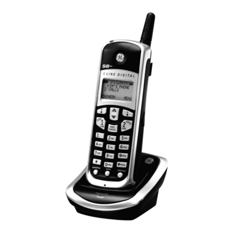
Figure 1. The standard Sigma7 in white

InternationalCommunications Group,Inc.
User’s Guide and Installation Manual
Sigma7
Aviation Telephone Handset
Sigma7
2
April 2006
Use or disclosure of information on this page is subject to the restrictions in the proprietary notice of this document.
THIS PAGE IS INTENTIONALLY LEFT BLANK.
Table of contents
