International Refrigeration Products WHP49230R User manual

WINDOW
HEAT PUMP
USER MANUAL
950-0190revD 02/19/2014
FOR MODELS:
COOLING
CAPACITY
HEATING
CAPACITY
WHP49230R
WHP49ZR
9,2
00
/9,500
BTU
11,200/11,600 BTU
WHP412230R
WHP412ZR
8,100/8,400
BTU
10,000/10,300BTU

Page 1
CONTENTS
INSTALLATION REQUIREMENTS.......................................................................................................................2
Tools and Parts............................................................................................................................................2
Location Requirements................................................................................................................................3
Electrical Requirements...............................................................................................................................4
INSTALLATION INSTRUCTIONS.........................................................................................................................5
Unpacking....................................................................................................................................................5
Window Installation......................................................................................................................................5
Wall Installation............................................................................................................................................8
Complete Installation ...................................................................................................................................9
AIR CONDITIONER USE...................................................................................................................................10
Air Conditioner Controls.............................................................................................................................12
Remote Control..........................................................................................................................................12
Normal Sounds..........................................................................................................................................13
Drain Cup Installation and Operation..........................................................................................................13
AIR CONDITIONER CARE................................................................................................................................14
Cleaning the Air Filter.................................................................................................................................14
Cleaning the Front Panel ...........................................................................................................................14
Repairing Paint Damage of Outside Case..................................................................................................14
Annual Maintenance..................................................................................................................................14
TROUBLE SHOOTING......................................................................................................................................15
SPECIFICATIONS.............................................................................................................................................17
WARRANTY......................................................................................................................................................18
FOREWORD
•The appearance of the units that you purchase may be slightly different from the ones described in this manual,
but will not affect proper operations and usage.
•Please read carefully the sections corresponding to the specific model you have, and keep the manual in a safe
place for reference.
•The refrigerant used in your portable air conditioner is an environmentally safe and friendly.
ATTENTION
•Keep small children away from portable unit.
•Do not modify or otherwise defeat the plug.
•The appliance shall be installed and operated in accordance with National Electrical Code regulations.
•Do not operate your unit in the cooling mode when the outside temperature is below 61°F. Do not opera te your
unit in the heating mode when outside temperature is above 86°F.
•If the supply cord is damaged, it must be replaced by a qualified person in order to avoid a fire hazard.
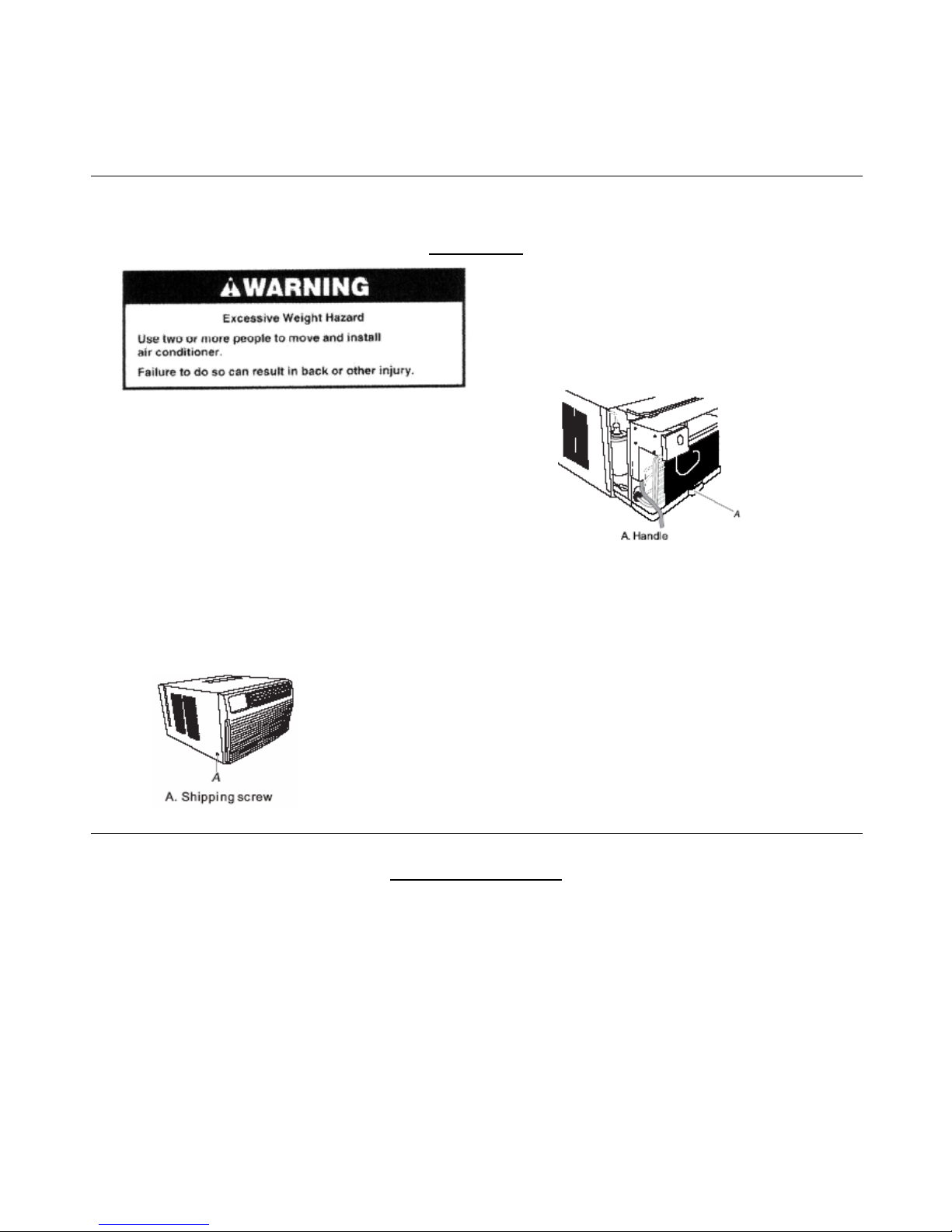
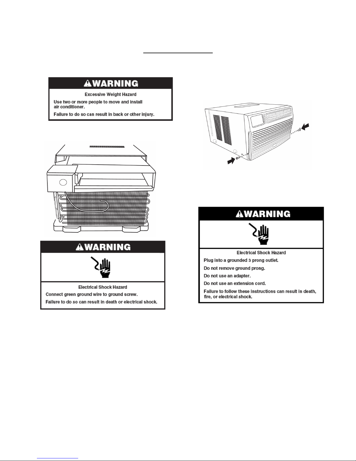
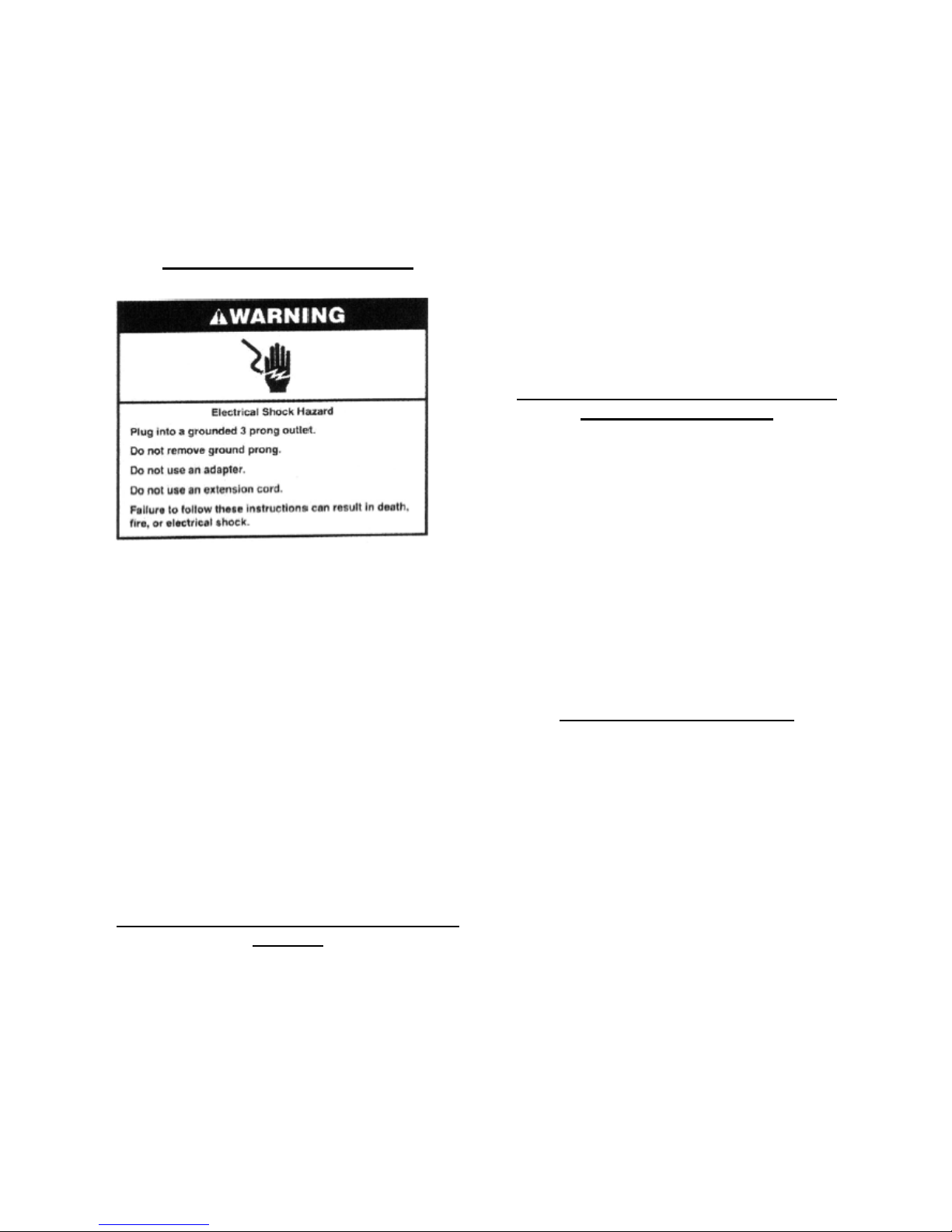
IMPORTANT SAFETY INSTRUCTIONS
WARNING: To reduce the risk of fire, electrical shock or injury when using your air conditioner, follow these basic
precautions:
•Plug into a grounded 3 prong outlet.
•Do not remove ground prong.
•Do not use an adapter.
•Do not modify plug on power cord. If plug
doesn’t fit electrical outlet, have proper outlet
installed by qualified electrician
.
•Do not use an extension cord.
•Do not have a fuse in the neutral or ground
circuit.
•Unplug units before servicing.
•Use two or more people to move and install air
conditioner.
Page 2
INSTALLATION REQUIREMENTS
Tools and Parts
Gather the required tools and parts before starting installation.
Read and follow the instructions provided with any tools listed here.
Tools Needed
Flat-blade and Phillips head screwdriver
Drill and 3/16” or smaller bit
Pencil
Ruler or tape measure
Level
Scissors or Utility knife
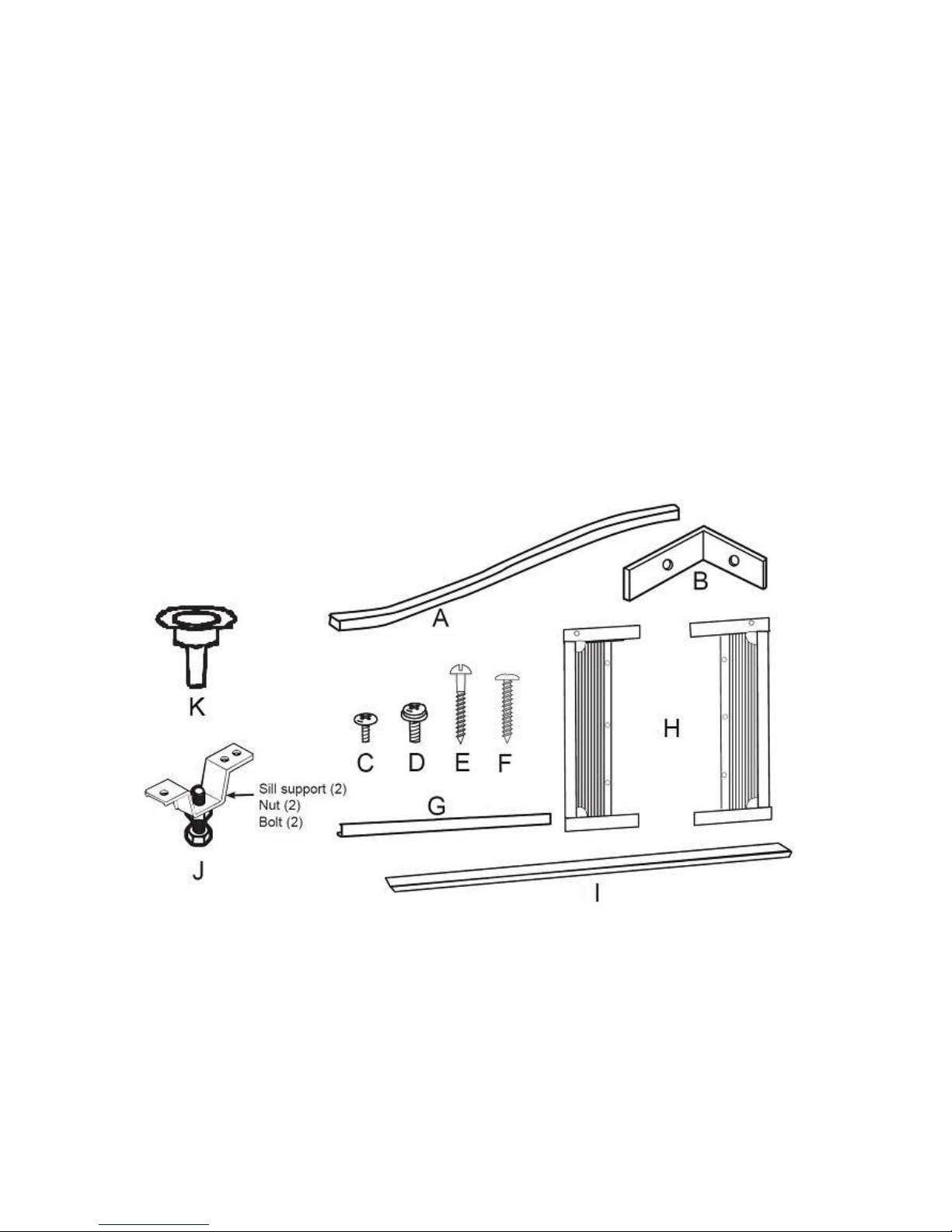
Parts Supplied
A. Foam window sash seal
B. Window lock brackets (2)
C. #10 x 1/4” pan-head Phillips screws (6)
D. #10 x 3/8” pan-head Phillips screws (3 or 7)
E. #10 x 3/4” round-head screws (6)
F. #10 x 1/2” pan-head Phillips screws (3)
G. Top channel
H. Side curtains (2)
I. Foam seal
J. Sill support (2) Nut (2) Bolt (2)
K. Condensate Drain Cup (1)
NOTE:
Mounting Parts provided varies per unit of different capacity. Please check your accessories bag carefully
when you open the carton.
Installation parts are supplied for double-hung windows up to 39” wide.
Page 3
Location Requirements
IMPORTANT: Observe all governing codes and
ordinances.
Check the location where air conditioner will be
installed. Proper installation is your responsibility.
Make sure you have everything necessary for
correct installation.
The location should provide:
•Grounded electrical outlet within 4 ft (122
cm) of where the power cord exits the air
conditioner.
NOTE: Do not use an extension cord.
•Free movement of air in room to be cooled.
•A large enough opening for the air
conditioner.
•Adequate wall support for weight of air
conditioner. Air conditioner weights up to 96
lbs (43.6 kg).
NOTE: Cabinet louvers & rear of the air
conditioner must not be obstructed. Air must be
able to pass freely through the cabinet louvers.
The rear of air conditioner must be outdoors. Not
inside a building or garage.
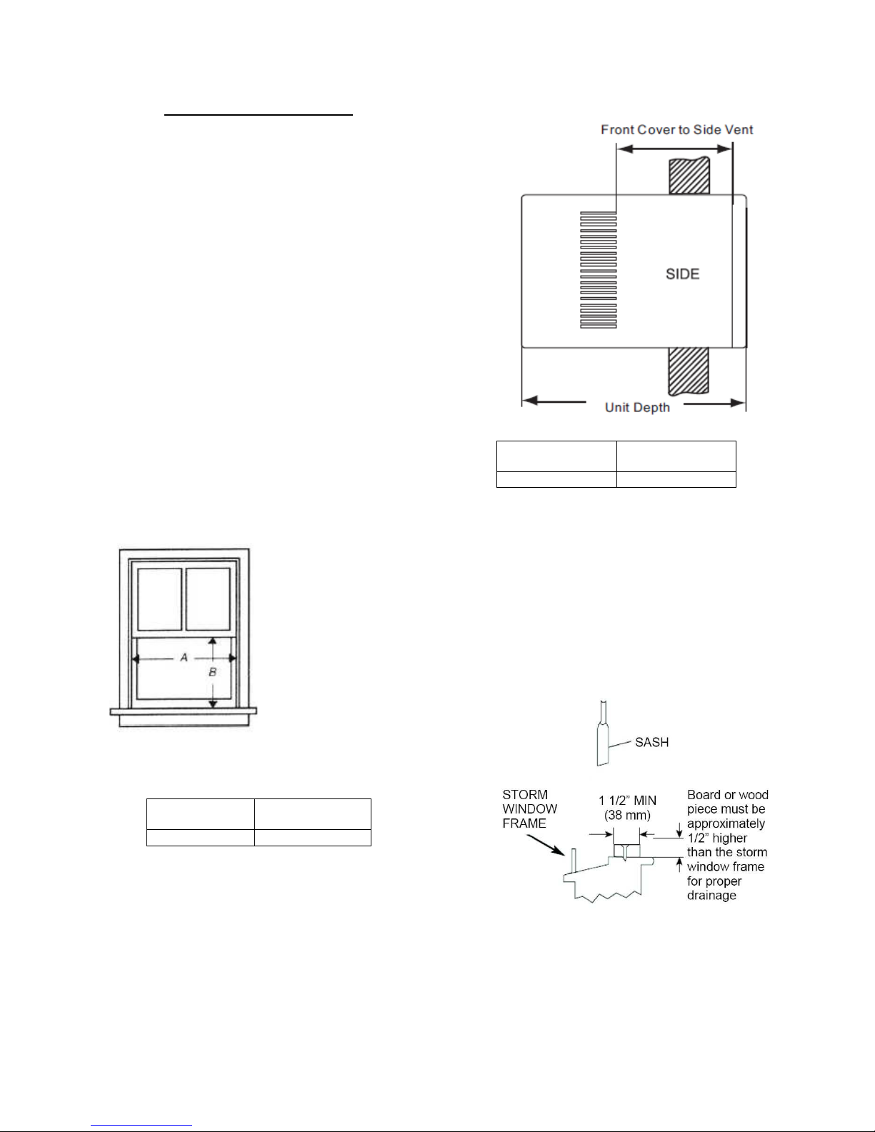
Window Requirements:
These instructions are for
a standard double hung
window. You will need to
modify them for other
types of windows.
The air conditioner can be
installed without the
accordion panel if needed
to fit in a narrow window.
See Window Opening
dimensions.
All supporting parts must be secured to firm
wood, masonry or metal.
Follow the dimension in TABLE -1.
Dim. A –
Opening Width Dim. B - Min
Vertical Opening
27”-39” 16 1/4”
TABLE -1
Thru-Wall Installation Requirements:
The air conditioner can be Thru-Wall installed.
The side louvers must never be blocked.
Table -2 provides the maximum wall thickness –
dimension from the outer case to side air louvers.
Front Cover to
Side Vent Unit Depth
5 1/2” 23 5/8”
TABLE -2
Storm Window Requirements:
A storm window frame will not allow the air
conditioner to tilt properly which in turn will keep
it from draining properly. To adjust for this,
attach a board or piece of wood to the sill. The
board or wood piece should have a depth of at
least 1 1/2”. Make sure the board or piece of
wood is approximately 1/2” higher than the storm
window frame. This will allow the air conditioner
to tilt enough for proper drainage. See FIG-1.
FIG-1

Page 4
Electrical Requirements
LCDI TYPE
Wiring Requirements
NEMA 6-20P
208/230-Volt (198 min to
253 max.)
0 to 16 amps
20-amp time-delay fuse or
circuit breaker
Use on single outlet circuit
only.
TABLE - 3
Recommended Grounding Method
This air conditioner must be grounded. This air
conditioner is equipped with a power supply cord
having a grounded 3 prong plug. To minimize
possible shock hazard, the cord must be
plugged into a mating, grounded 3 prong outlet,
grounded in accordance with all local codes and
ordinances. If a mating outlet is not available, it
is the customer’s responsibility to have a
properly grounded 3 prong outlet installed by a
qualified electrical installer.
It is the customer’s responsibility:
•To contact a qualified electrical installer.
•To assure that the electrical installation
is adequate and in conformance with
National Electrical Code, ANSI/NFPA
70- latest edition, and all local codes
and ordinances.
Power Supply Cord
NOTE: Your unit’s device may differ from the
ones shown.
This room air conditioner is equipped with a power
supply cord required by UL. This power supply cord
contains state-of-the-art electronics that sense leakage
current. If he cord is crushed, the electronics detect
leakage current and power will be disconnected in a
fraction of a second.
To Test your power supply cord:
1. Plug power supply cord into a grounded 3
prong outlet.
2. Press RESET
3. Press TEST (listen for click, Reset button
will trip and pop out).
4. Press and release RESET (listen for click;
Reset button will latch and remain in). The
power supply cord is ready for operation.
NOTES:
•The reset button must be pushed in for
proper operation.
•The power supply cord must be replaced if it
fails to trip when the test button is pressed
or fails to reset.
•Do not use the power supply cord as an
off/on switch. The power supply cord is
designed as a protective device.
•A damaged power supply cord must be
replaced with a new power supply cord
obtained from the product manufacturer and
must not be repaired.
•The power supply cord contains no user
serviceable parts. Opening the tamper-
resistant case voids all warranty and
performance claims.
Page 5
INSTALLATION INSTRUCTIONS
Unpacking
Remove packaging materials.
•Remove and dispose or recycle all packaging
materials.
•Remove tape and glue residue from surfaces before
turning on the air conditioner. Rub a small amount of
liquid dish soap over the adhesive with your fingers.
Wipe with warm water and dry.
•Do not use sharp instruments, rubbing alcohol,
flammable fluids, or abrasive cleaners to remove
tape or glue. These products can damage the
surface of your air conditioner.
•Handle air conditioner gently.
1. Remove air conditioner from carton and place it on
cardboard.
2. Remove shipping screws from both sides of cabinet.
3. Remove front panel by removing 2 Phillips
screws on both sides.
4. Pull on handle to slide air conditioner out of
cabinet. Place air conditioner on cardboard.
5. Remove any packing foam from inside of unit.
NOTE: Do not lift, push, pull or remove any
expanded polystyrene (foam) from inside the air
conditioner. It is not packing material.
Window Installation
NOTES:
•Handle air conditioner gently
•Be sure your air conditioner cabinet does not fall
out of the opening during installation or removal.
•The location where the power cord exits the air
conditioner should be no more than 4 ft (122cm)
from a grounded 3 prong outlet.
•Do not block the louvers on the front panel.
•Do not block the louvers on the outside of the air
conditioner.
Attach Top Channel
NOTE: Attach top channel and side curtains to air
conditioner cabinet before placing cabinet in window.
•Locate supplied bag of screws.
•Place top channel on top of air conditioner
cabinet, lining up the 3 holes in top channel with
3 holes on top of air conditioner cabinet.
•Using 3 - #10 x 3/8” pan-head Phillips screws,
attach top channel to air conditioner cabinet.

Page 6
Attach side curtains
1. Locate provided bag of screws
2. Insert top and then bottom of right-hand curtain
housing in top and bottom curtain guides on air
conditioner cabinet.
Back View
Bottom View
3. Extend right-hand curtain outward so you may
insert the first screw through the middle hole of the
curtain. Using #10 x ¼” pan-head Phillips screw, screw
curtain to middle hole in air conditioner cabinet.
NOTE: This screw is required to correctly attach
curtain (top to bottom) to the air conditioner cabinet.
4. While the right hand curtain is still extended,
insert #10 x ¼” pan-head Phillips screws into the top
and bottom slots of curtain. Screw Curtain to the top
and bottom holes in air conditioner cabinet.
NOTE: Some curtains may have 2 slots on each end.
You will be able to see a mounting hole through the
correct slot.
5. Slide curtain housing into guides as far as it will
go.
6. Repeat above steps for left-hand curtain.
Attach Foam Adhesive Seal
Attach foam adhesive seal along the bottom of the
curtain bottom channel.
Install Cabinet into Window
•Handle air conditioner gently.
•Be sure your air conditioner cabinet does not fall
out of the opening during installation or removal.
•The location where the power cord exits the air
conditioner should be no more than 4 ft (122cm)
from a grounded 3 prong outlet.
•Do not block the louvers on the front panel.
•Do not block the louvers on the outside of the air
conditioner.
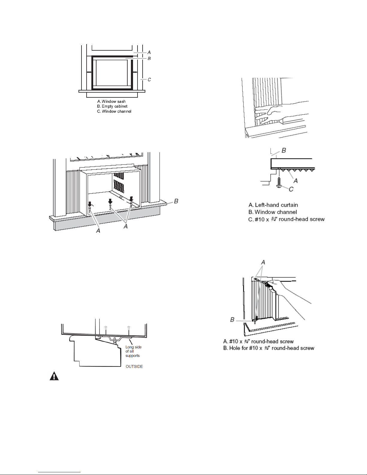
1. Center empty cabinet in window. Check that
lower rail of air conditioner cabinet is behind and
against back side of windowsill. Maintain a firm
hold on the air conditioner cabinet. Lower
window sash to hold cabinet in place. Top
channel must be on inside room of window sash.
2. Measure the distance between the right-hand
side of the cabinet and the inside of the window
channel
3. Repeat for left side. Adjust the cabinet until the
distance on each side is the same.
Page 7
4. Use a 3/16” drill bit to drill 3 starter holes ½”
deep through the 3 holes in the cabinet and into
the window sill.
5. Attach cabinet to windowsill with 3 - #10 x ½”
pan-head Phillips screws.
6. Check that the air conditioner cabinet is tilted ½
bubble on carpenters level to the outside so that
water will run to the outside.
On some models
Select the position that will place the sill supports
near the outermost point on the sill. Place the short
side of the sill supports, on the case bottom, toward
the window. Attach the sill supports to the case track
hole in relation to the selected position using 2 type
B screws in each support.
CAUTION:
Do not install this air conditioner in
a window if the bolts do not contact the window sill.
Attach Side Curtains to Window Frame
1. Pull left-hand curtain out until it fits into window
channel. Use a 3/32” drill bit to drill a starter hole
through the hole in the curtain housing and into
the lower window sash.
Front View
Top View
2. Insert one of the #10 x ¾” round-head screws
through hole and into lower window sash. Insert
one of the #10 x ¾” round-head screws through
threaded hole in top of curtain and one in bottom
of curtain.
3. Repeat for right-hand curtain.
Complete Window Installation
1. Insert foam seal behind the top of the lower
window sash and against the glass of the upper
window.
2. Place window-lock bracket on top of lower
window and against upper window sash.
Page 8
3. Use a 3/32” drill bit to drill a starter hole through
the hole in the bracket and into the window
sash.
4. Attach window-lock
bracket to window
sash with #10 x ¾”
round-head screw to
secure window in
place.
A. Window lock bracket (2)
B. Foam seal
C. Upper window glass
D. #10 x 1/2” pan-head Phillips screws (3)
Wall Installation
NOTES:
•Handle air conditioner gently.
•Be sure your air conditioner cabinet does not fall out of the opening during installation or removal.
•The location where the power cord exits the air conditioner should be no more than 4 ft (122cm) from a
grounded 3 prong outlet.
•Do not block the louvers on the front panel.
•Do not block the louvers on the outside of the air conditioner.
•It is the customer’s responsibility and obligation to have this product installed by a qualified technician familiar
with through-the-wall room air conditioner installations.
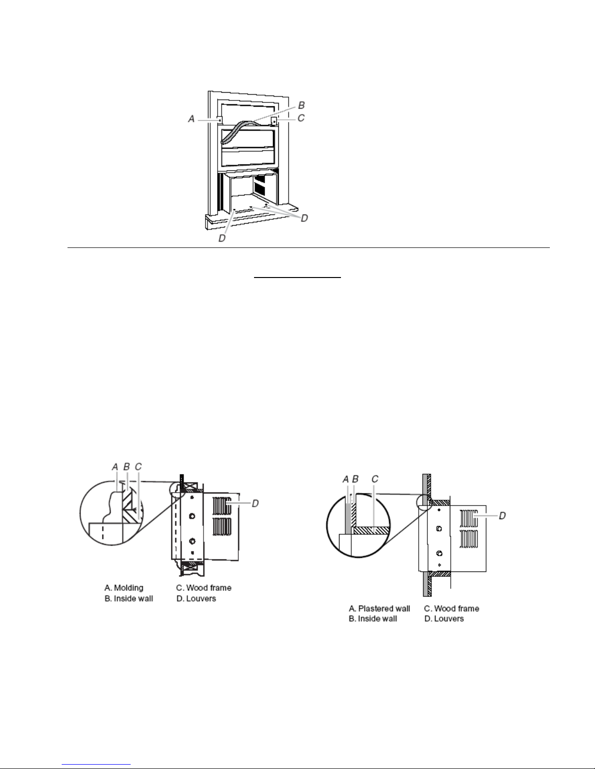
Option 1 – Wood, metal or plastic molding
When you are using wood, metal or plastic molding,
the wood frame should line up with inside wall as
shown.
Option 2 – Plastered wall with no molding
If the plastered wall is to be flush with the cabinet
and no molding is used, the wood frame must be set
½” (13mm) into the inside wall.
Page 9
Complete Installation
NOTE: Handle air conditioner gently.
1. Insert air conditioner into cabinet.
2. Install ground screws on both sides of cabinet.
3. Insert front tabs of front panel into top of cabinet and
swing front into place.
4. Attach bottom front of panel with front panel screws.
NOTE: For wall installations, if needed, install
molding around room side of cabinet.
5. Plug into a ground 3 prong outlet.
6. Press RESET on the power supply cord plug.

Page 10
AIR CONDITIONER USE
----------------------------------------------------------------------------------------------------------------------------------
Cool Mode Feature
Use the Cool mode at Low, Med, High or Auto Fan
Speed for cooling. Use the Temperature Increase
/Decrease pads to set the desired temperature between
64°F and 86°F in 1°F increments.
The display will indicate the set temperature in the cool
mode. An electronic thermostat is used to maintain the
room temperature. The compressor will cycle on and off
to keep the room at the set level of comfort. Set the
thermostat at a lower number and the indoor air will
become cooler. Set the thermostat at a higher number
and the indoor air will become warmer.
NOTE:
If the air conditioner is off and is then turned on while set
to a Cool setting or if turned from a fan setting to a Cool
setting, it may take approximately 3 minutes for the
compressor to start and cooling to begin.
Cooling Descriptions
For Normal Cooling—Select the Cool mode - Low or
Med fan speed - Select a normal cooling temperature.
For Maximum Cooling—Select the Cool mode - High
fan speed - Select a lower set temperature if necessary.
For Quieter and Nighttime Cooling—Select the Cool
mode - Low fan - Select a comfortable set temperature.
----------------------------------------------------------------------------------------------------------------------------------
Heat Mode Feature
Use the Heat mode at Low, Med, High or Auto Fan
Speed for heating. Use the Temperature Increase
/Decrease pads to set the desired temperature
between 64°F and 86°F in 1°F increments.
The display will indicate the set temperature in the heat
mode. Your window unit is heat pump with auxiliary
electric heating. Unit will select compressor operation
or electric heater depending on the difference between
room temperature and ambient temperature. The heat
pump and electric heater will not operate at the
same time.
NOTE:
Do not try to operate your air conditioner in the heating
ode when outside temperature is above 86°F, the
inside evaporator coil will freeze up.
When the outdoor temperature is below 55°F the
electric heat will be activated and the compressor will
turn off.
----------------------------------------------------------------------------------------------------------------------------------
Fan Only Mode Feature
Use the Fan Only Mode at Low, Med or High fan speed
to provide air circulation and filtering without cooling.
Since fan-only settings do not provide cooling, a Set
Temperature cannot be entered. The room temperature
will appear in the display.
NOTE: Auto Fan Speed cannot be used when in the Fan
Only Mode.
----------------------------------------------------------------------------------------------------------------------------------
Energy Saver Mode Feature – Cooling Only
The energy saver mode operates the cooling system
only.
ON – The will cycle on and off with the compressor.
This may result in wider variations of room temperature
and humidity.
OFF – The fan operates continuously as the
compressor cycles on and off.
NOTE: The fan may continue to run for a short time
after the compressor cycles off.
----------------------------------------------------------------------------------------------------------------------------------
Page 11
----------------------------------------------------------------------------------------------------------------------------------
Auto Fan Speed Feature
The Auto fan speed allows the speed to be
automatically adjusted as needed to provide optimum
comfort. If the room needs more cooling, the fan speed
will automatically increase.
If the room needs less cooling or heating, the fan speed
will automatically decrease.
NOTE: Auto Fan Speed cannot be used when in the Fan
Only Mode.
----------------------------------------------------------------------------------------------------------------------------------
Auto Restart - Power Outage Recovery Feature
In the case of a power outage or interruption, the unit
will automatically restart in the settings last used after
the power is restored. If the Delay 1–24hr feature was
set, it will resume countdown. You may need to set a
new time if desired.
----------------------------------------------------------------------------------------------------------------------------------
Starting Your Air Conditioner - Digital Control
IMPORTANT:
•If you turn the air conditioner off, wait at least 3 minutes before turning it back on. This prevents the air
conditioner from blowing a fuse or tripping a circuit breaker.
•Press buttons (Increase ▲and Decrease ▼)at the same time for 3 seconds could switch temperature ºF/
ºC in display.
•Do not try to operate your air conditioner in the cooling mode when outside temperature is below 64ºF. Do
not try to operate your air conditioner in the heating mode when outside temperature is above 86 ºF. The
inside evaporator coil will freeze up, and the air conditioner will not operate properly.
NOTE: The touch pad or remote control can be used to change settings.
1. The display indicates the set temperature when
in Heat/Cool/Energy Saver mode.
2. Indicates time remaining on the delay timer.
3. Indicates the room temperature when in Fan
Only mode.
LED will illuminate during mode or timer
changes. After changes are completed the
LED will turn off.

Page 12
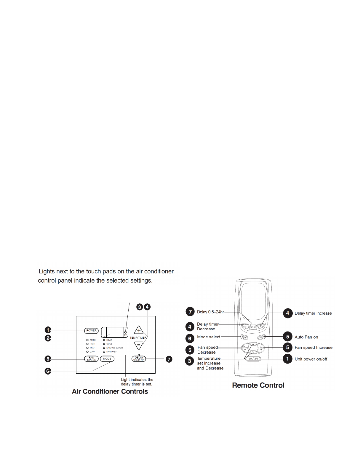
Air Conditioner Controls
1. Power button – Turns the air conditioner on and
off.
2. Display – Indicates the set temperature when in
Heat/Cool/Energy Saver mode. Indicates time
remaining on the delay timer. Indicates the room
temperature when in Fan Only mode. The Set
LED will turn on while settings are changed.
3. Temp buttons (Increase ▲/ Decrease ▼) –
Used to set temperature when in Cool/ Heat/
Energy Saver mode. The Set LED will turn on
while increasing or decreasing temperature.
4. Timer buttons (Increase ▲/ Decrease ▼)
Each touch of the (Increase ▲/ Decrease ▼)on
the unit of the (Increase ▲/ Decrease ▼) on the
remote control will set the delay time when using
the Delay 0.5-24hr timer. The Set LED will turn on
while setting the timer.
5. Fan Speed button – Used to select the fan speed
to Low, Med, High or Auto on the unit. The LED
marked “Auto” “High”, “Med”, or “Low” will
illuminate to indicate which fan speed is selected.
NOTE: On the remote control, use the fan speed
Increase + / Decrease - buttons to set the fan
speeds to Low, Med or High. Use the Auto button
to turn Auto fan on.
6. Mode button – Used to select between Fan Only,
Energy Saver, Heat or Cool mode of operation. In
the Fan only mode, since Fan only settings do not
provide cooling, a Set temperature can not be
entered. The display will indicate the room
temperature. See Energy Saver mode feature on
page 11.
NOTE: In Cool mode, the fan will not turn off after
the set point temperature has been satisfied. In
Heat mode, the fan will turn off after the set point
is satisfied. When the outdoor temperature is
below 55°F the electric heat will be activated and
the compressor will turn off.
7. Delay Button - Used to select the amount of time
before the air conditioner turns off (when on), or
the amount of time before the air conditioner turns
on (when off). Programmable in 0.5 hour
increments from 1 to 10 hours and 1 hour from 11
to 24 hours.
How to set:
Delayed “ON”:
Air Conditioner must be off.
Press the Delay 0.5-24hr button or DELAY on
remote control.
The Delay 0.5-24hr light will turn on and the
display will indicate the number of hours before
the air conditioner will turn on. To change the time
before turn on, press the Increase ▲or
Decrease ▼buttons until the desired number of
hours before turn on is reached (0.5 to 24 hrs).
Delayed “OFF”:
Air Conditioner must be on.
Press Delay 0.5-24hr button or DELAY on
remote control.
The Delay 0.5-24hr light will turn on and the
display will indicate the number of hours before
the air conditioner will turn off. To change the time
before turn off, press the Increase ▲or
Decrease ▼buttons until the desired number of
hours before turn on is reached (0.5 to 24 hrs).
To review the amount of time remaining on the
timer, press the Delay0.5-24 hr button one time.
If you desire to increase or decrease the amount
of time remaining, use the Increase ▲or
Decrease ▼buttons to set a new time.
To cancel the Timer, press the Delay0.5-24 hr
button until the Delay0.5-24 hr light extinguishes.
Remote Control
•Be sure that there are no obstructions
between the receiver and the remote
controller.
•The remote control signal has a range of up to
20 feet.
•Do not drop or throw the remote controller.
•Do not let any liquid in the remote controller or
put the remote controller under direct sunlight
or any place where it is very hot.
•Replace two AAA batteries once a year, or as
required.

Page 13
Normal Sounds
When your air conditioner is operating normally, you may hear sounds such as:
•Droplets of water hit the condenser, causing a
pinging or clicking sound. The water droplets
help to cool the condenser.
•Air movement from the fan.
•Clicks from the thermostat cycle.
•Vibrations or noise due to poor wall or window
construction.
•A high-pitched hum or pulsating noise caused
by the modern high-efficiency compressor
cycling on and off.
Drain Cup Installation and Operation
Your air conditioner uses a system where the water removed from the indoor air is channeled to the outdoor side
of the unit. The outdoor fan blade has a “slinger” ring attached to it that dips into the water and slings the water
onto the outdoor coil surface. This is the sound of water you hear during normal operation. The water quickly
evaporates on this warm surface and improves the efficiency of your air conditioner. In normal conditions the unit
can evaporate the water as fast as it is removed from the indoor air.
When it is in very humid weather, excess amounts of water may drop off the unit chassis. You could install the
condensate drain cup provided with the unit if this becomes a problem. See below Installation Instructions.
•Remove the unit chassis from the outer case. Refer to Page 6.
•Insert the condensate drain cup through the recessed 1/2” hole on the back center of the outer case.
•Place a 1/2” diameter hose or tube (not provided) on the drain cup bottom spout. The hose allows you to
route where you want the excess water to go.
•Reinsert the unit chassis into the outer case. The unit basepan overflow hole will be positioned directly
above the drain cup and will collect any water that might run out.

Page 14
AIR CONDITIONER CARE
Your new air conditioner is designed to give you many years of dependable service. This section tells you how to
clean and care for your air conditioner properly. Call your local authorized dealer for an annual checkup. Remember,
the cost of this service call is your responsibility.
__________________________________________
Cleaning the Air Filter
The air filter is removable for easy cleaning. A clean
filter helps remove dust, lint, and other particles from
the air and is important for best cooling and operating
efficiency. Check the filter every 2 weeks to see
whether it needs cleaning.
NOTE: Do not operate the air conditioner without the
filter in place.
1. Turn off the air conditioner.
2. Grasp filter handle and slide filter out of unit.
3. Use a vacuum cleaner to clean air filter. If air filter
is very dirty, wash it in warm water with a mild
detergent. Do not wash air filter in the dishwasher or
use any chemical cleaners. Air dry filter completely
before replacing to ensure maximum efficiency.
Cleaning the Front Panel
1. Turn off the air conditioner
2. Remove the air filter and clean it separately. See
Cleaning the Air Filter.
3. Wipe the front panel with a soft damp cloth.
4. Air dry front panel completely.
__________________________________________
Repairing Paint Damage of Outside
Case
Check once or twice a year for paint damage. This is
very important, especially in areas near oceans or
where rust is a problem. If needed, Touchup with a
good grade enamel paint.
NOTE: To reduce paint damage during the winter,
install a heavy duty cover over the air conditioner
cabinet.
__________________________________________
Annual Maintenance
Your air conditioner needs annual maintenance to help
ensure steady, top performance throughout the year.
Call your local authorized dealer to schedule an
annual checkup. The expense of an annual inspection
is your responsibility.
4. Replace air filter by sliding filter into filter door.
Page 15
TROUBLE SHOOTING
Before calling for service, try the suggestions below to see whether you can solve your problem without outside help.
Air conditioner will not operate
1. The power supply cord is unplugged. Plug into
a grounded 3 prong outlet. See “Electrical
Requirements”.
2. The power supply cord has tripped (Reset
button has tripped). Press and release RESET
(listen for click; Reset button will latch and remain
in) to resume operation.
3. A household fuse has blown, or a circuit
breaker has tripped. Replace the fuse or reset
the circuit breaker. If the problem continues, call
an electrician. See “Electrical Requirements”.
4. Depending on model, the Power button has
not been pressed or the Fan control is turned
to OFF. Press POWER or turn the Fan control to
an active setting.
5. The local power has failed. Wait for power to be
restored.
Air conditioner blows fuses or trips circuit
breakers
Too many appliances are being used on the same
circuit. Unplug or relocate appliances that share the
same circuit.
Time-delay fuse or circuit breaker of the wrong
capacity is being used. Replace with a time-delay
fuse or circuit breaker of the correct capacity. See
“Electrical Requirements”.
An extension cord is being used. Do not use an
extension cord with this or any other appliance.
You are trying to restart the air conditioner too
soon after turning the unit off. Wait at least 3
minutes after turning the unit off before trying to restart
the air conditioner.
Air conditioner power supply cord trips
(Reset button pops out)
Disturbances in your electrical current can trip
(Reset button will pop out) the power supply cord.
Press and release RESET (listen for click; Reset
button will latch and remain in) to resume operation.
Electrical overloading, overheating, pinched cord
can trip (Reset button will pop out) the power
supply cord.
After correcting the problem, press and release
RESET (listen for click; Reset button will latch and
remain in) to resume operation.
NOTE: a damaged power supply cord must be
replaced with a new power supply cord obtained from
the product manufacturer and must not be repaired.
Air conditioner runs too long
The current air conditioner replaced an older
model. The use of more efficient components may
cause the air conditioner to run longer than an older
model, but the total energy consumption will be less.
Newer air conditioners do not emit the blast of cold air
you may be accustomed to from older units, but this is
not an indication of lesser cooling capacity or
efficiency. Refer to the efficiency rating (EER) and
capacity rating (in BTU/hr.) marked on the air
conditioner.
The air conditioner is in a heavily occupied room,
or heat-producing appliances are in use in the
room. Use exhaust vent fans while cooking or bathing
and try not to use heat producing appliances during
the hottest part of the day. A higher capacity air
conditioner may be required, depending on the size of
the room and external heating/cooling.

Page 16
Air Conditioner cycles on and off too
often, or does not cool room in cooling
mode
The air conditioner is not properly sized for your
room.
Check the cooling capabilities of your room air
conditioner. Room air conditioners are not designed to
cool multiple rooms.
The filter is dirty or obstructed by debris. Clean the
filter.
The inside evaporator and outside condenser coils
are dirty or obstructed by debris. See “Annual
Maintenance.
There is excessive heat or moisture (open
container cooking, showers, etc.) in the room. Use
a fan to exhaust heat or moisture from the room. Try
not to use heat-producing appliances during the
hottest part of the day.
The louvers are blocked. Install the air conditioner in
a location where the louvers are free from curtains,
blinds, furniture, etc.
The outside temperature is below 65ºF (18ºC). Do
not try to operate your air conditioner in the cooling
mode when the outside temperature is below 65ºF
(18ºC).
The temperature of the room you are trying to cool
is extremely hot. Allow extra time for the air
conditioner to cool off a very hot room.
Windows or doors to the outside are open. Close
all windows and doors.
The temperature set point or
Thermostat control is not at a cool enough setting.
Adjust the temperature set point to a cooler setting by
pressing the minus button to reduce the temperature
or adjust the Thermostat control to a cooler setting by
turning the knob clockwise. Turn the Fan control to
HIGH or Turbo Cool.
Temperature on display does not match
room temperature
When the compressor and fan motor turn off
during Power Saver mode, or after you turn off the
unit, a lower temperature reading than the actual
room temperature may be displayed for a short
period of time. This lower temperature reading is
caused by the temperature sensor being located close
to the cold evaporator coil. The actual room
temperature will display within a few minutes.
Water drips from cabinet into your house
The air conditioner is not properly leveled. The air
conditioner should slope slightly downward toward the
outside. Level the air conditioner to provide a
downward slope toward the outside to ensure proper
drainage. See the Installation instructions.
NOTE: Do not drill a hole into the bottom of the metal base and condensate pan.

Page 17
SPECIFICATIONS
Model
WHP49230R
WHP49ZR
WHP412230R
WHP412ZR
Cooling Capacity 9200/9500 11200/11600
Heating Capacity 8100/8400 10000/10300
Electric Heat Capacity
8500/10700
8500/10700
EER Rating 10 9.5
COP Rating 9.9 8.9
Dehumidification (pints/hr) 4 4.54
Air Flow Max (CFM) 282 282
Rated Voltage 208-230 208-230
Operating Voltage Range 198-253 198-253
Frequency/Cycle 60 60
Cooling Amps 4.8/4.6 5.9/5.5
Cooling Watts 920/950 1180/1220
Heating Amps 4.5/4.2 5.6/5.1
Heating Watts 820/850 1130/1160
Electric Heat Amps 14.6/16 14.6/16
Electric Heat Watts 2765/3575 2765/3575
Plug Type - LCDI NEMA 6-20P NEMA 6-20P
Power Cord Rating (amps) 18A 18A
Power Cord Length (Inches) 59" 59"
Minimum Circuit Breaker Size (amps) 20A 20A
Minimum Circuit Capacity (amps) 20A 20A
Refrigerant Charge - R410a (oz.)
24.69
28.22
Max dbA Level (Indoor/Outdoor) 62/66 62/66
4 Way Air Adjustment Yes Yes
2 Way Air Swing N/A N/A
Air Discharge top front top front
Motor Type ball bearing ball bearing
Fan Motor Capacitor 4 µF 4 µF
Controls Remote Remote
Cooling Ambient Operating Temperature
<109 °F (note 2) <109 °F (note 2)
Unit Size (Inches)
Width 22 19/32 22 19/32
Depth 23 5/8 23 5/8
Height 15 5/16 15 5/16
Window Width Opening (Inches) 27"-39" 27"-39"
Thru. Wall Max. Thickness (Inches) 5 1/2 5 1/2
Weight Gross/Net. (Lbs) 110.2/90.4 114.6/95.9
NOTE: 1) Product specification subject to change without notice.
2) Above 109 °F unit will still operate but efficiency starts to decline.

Page 18
WARRANTY
International Refrigeration Products warrants that the product supplied is free from defects in
material and workmanship. This warranty is valid as long as this product is properly handled,
installed, operated and serviced in accordance with the Installation and Operating Instructions
shipped with this unit, and the warranty card is completed and mailed no later than 30 days after
date of purchase. All warranty claims must be made within one (1) year (five (5) years for
compressor) from date of purchase (unless national regulations require a longer registration
period).
This warranty provides free replacement of defective parts only. Labor is not covered under this
warranty. Replacement as a result of normal wear and tear is not covered under this
warranty.
Additional claims are excluded, unless required by national regulations. International Refrigeration
Products Inc. is not responsible for incidental, consequential, direct, or indirect damages, or
expenses relating to the use of, or the inability to use the product for any purpose. Other implied
warranties are excluded.
This constitutes International Refrigeration Products’ warranty obligation and replaces any and all
prior warranties for this product.
International Refrigeration Products Inc
1035 Wheeler Way
Langhorne, PA 19047
Service - Tel: 215-750-9876 Fax: 215-750-1169
Hours: 8:00 AM to 4:30 PM EST
Website: www.irproducts.biz
This manual suits for next models
3
Table of contents
Other International Refrigeration Products Heat Pump manuals


Popular Heat Pump manuals by other brands


Samsung
Samsung AM BXVGFH/AA Series Technical data book

Novelan
Novelan SIC Series operating manual

Carrier
Carrier 38YKB Installation and start-up instructions

Carrier
Carrier WEATHERMASTER 2000 operating guide

Solamics
Solamics Bunsen Air Installer manual

Daikin
Daikin VRV Aurora RXLQ-TATJU Series Service manual

POOLEX
POOLEX Nano Easy start guide

Viessmann
Viessmann VITOCAL 242-G Installation and service instructions

Carrier
Carrier 48VT-B Owner's information manual

Hitecsa
Hitecsa EWFAIB Installation, operation and maintenance instructions

Nibe
Nibe F370 Installer manual

Panasonic
Panasonic PAW-VP1000LDHW Technical manual