International Refrigeration Products MEDALLION SERIES Manual
APPLICATION:
This thermostat is a programmable 24 volt Heating and Cooling
Digital Temperature Control with automatic changeover from heating
to cooling and back again. It can be used for residential and light
commercial systems. They are ideal for use with most heating and
cooling systems with multi-stages. The large, easy to read display
makes the thermostat easy to operate and simple to program.
Backlighting makes it easy to read the display in the dark.
International Refrigeration Products, Inc.
1035 Wheeler Way
Langhorne, PA 19047
Service:
Monday to Friday
8:00 AM to 4:30 PM EST
Tel: 215-750-9876
1. Caution: Make sure that power has been disconnected.
2. All wiring must comply with applicable codes and ordinances.
3. A thorough check-out of the system should be made after
installation is complete.
4. If retrofitting old thermostat, remove old thermostat from wall,
carefully noting the wire connections on the old unit. Record
wire color and terminal legends in spaces provided.
5. Using the mounting screws provided, mount the thermostat to the
wall or junction box.
6. Connect wire cables according to your wire color chart.
7. Push excess cable wires back into the wall while positioning
thermostat. If there is a draft, pack the opening with non-
combustible material.
!
SPECIFICATIONS:
Setpoint Temperature Range: 40.0
Display Format: Liquid Crystal Display (LCD)
Sampling Rate: Every 30 seconds
Accuracy: ± 1°F
Power Source: 24V, 30V maximum AC or DC
Class II Supply and Wiring
Load Rating: 1.5 Amp maximum total load
Fan Control: selectable - auto cycle or continuous
Heat/Cool Control: 2 heat and 2 cool circuits
LCD Backlighting: auto or continuous
°F to 95.0°F (5.0°C to 35.0°C)
:
This device should be installed and serviced by a qualified
technician. Junction box mounting is highly recommended.
General Installations
function
Single 24V Feed
Single 24V Common
Cooling Aux/Damper
Heating Aux/Damper
Fan
Cool Stage 1
Heat Stage 1
Cool Stage 2
Heat Stage 2
Terminal
terminals
R
C
O
B
G
Y1
W1
Y2
W2
Thermostat
wire color
Cable
MEDALLION SERIES
INSTALLATION / OPERATING INSTRUCTIONS
1
R24V Class II
Supply Transformer
Heat
Relay
Stage 2
W2
Cool
O
Heat
B
C
Cool
Relay
Stage 2
Y2
Cool
Relay
Stage 1
Y1
Fan
Relay
G
Heat
Relay
Stage 1
W1
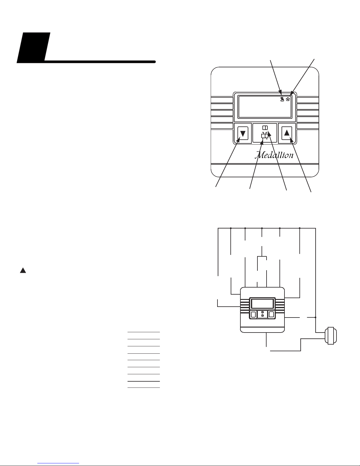
Manual
Actual
TEMP
Increase
Temperature
Cool
Icon
Heat
Icon
Fan
Switch
System
Switch
Decrease
Temperature
FAN
ON FAN
AUTO
AUTO
COOL OFF
HEAT
72.3 F
0
Reversing
Valve
Refrigeration Products
International
IRP
Please refer to the owner’s manual for programming instructions.
Model: TDAP24-AH22-CB
Cycle Rate Selection:
The cycle rate selection determines the cycle rate for both heating
and cooling. All units are shipped with a cycle rate of 1.0, the medium
rate. To change the cycle rate press the “up” and “down” buttons
together for approximately 10 seconds. The display will change to
diff and 1.0. Use the “up” or “down” button to select a new cycle rate.
After approximately 15 seconds the display will return to normal.
Selection Criteria: 0.5 is the fastest cycle rate, 2.0 is the slowest.
Trouble Shooting Tests:
Using a voltmeter, confirm the supply voltage. With the system
switch in the OFF position and the fan switch in the auto position
the voltage should measure between 18VAC and 30VAC from R
and the other terminals. Confirm supply voltage between R and C.
Briefly press the reset button to initialize the processor. The LCD
should power up.
To check Continuity: (Using a Voltmeter with all loads connected)
A) When thermostat is calling for Cool, meter should read 0VAC
from “R” to “Y1”. When Cool is deactivated, meter should read
24VAC from “R” to “Y1”. (“Y2" is offset 2°F above “Y1")
B) When thermostat is calling for Heat, meter should read 0VAC
from “R” to “W1”. When Heat is deactivated, meter should read
24VAC from “R” to “W1”.(“W2" is offset 2°F above “W1")
C) When the fan switch is in the AUTO position and the system
switch is in the OFF position, meter should read 24VAC between
“R” and “G”. When the fan switch is in the ON position and the
system switch is in the OFF position, the meter should read 0VAC
between “R” and “G”.
Setting Parameters:
There are six parameters to set depending on the model. °F/°C
selection, fan mode selection, backlight mode selection, display
selection, water source heat pump selection and cycle rate selection.
°F/°C Selection:
All units are shipped in °F display mode. °C can be selected by
moving the jumper to the °C position. Press reset after changing
jumper position. Warning: Resetting
program schedule and replace it with the factory default schedule.
Fan Mode Selection:
All units are shipped with the jumper in the right position. The fan then
cycles only with cooling calls normal for gas or oil heat. The fan mode
jumper in the left position selects the fan to cycle with both heating
and cooling calls necessary for some electric heat systems.
Blacklight Mode Selection:
All units are shipped with the backlight jumper in the left position,
auto mode. The backlight comes on whenever the up or down button
is pressed. The backlight jumper in the right position keeps the
backlighting on continuously.
Display Button Selection:
All units are shipped with the display alternation between room
temperature, current setpoint and time-of-day. Pressing the display
button selects the display to show only room temperature or alternate
between actual room temperature, current setpoint and time-of-day.
Water Source Heat Pump Selection:
This selection is for water source heat pumps. If you do not have a
water source heat pump you may skip this step. If you have a water
source heat pump follow these steps. Hold the “Display” button down
and then press the “up” button. SHC will appear on the display.
Release both buttons. Change SHC to HP by pressing the “down”
button. After approximately 20 seconds the display will return to
normal. Also set the fan mode jumper to the left hand position.
°F/°C will erase any user
Testing Basic Functions:
Check the basic functions in the manual mode. Turn the program
selection dial, located under the flip down cover, to “MANUAL”.
OFF:
1. With system switch in the “OFF” position, the thermostat turns off
the heating and cooling systems.
2. Setpoints cannot be changed in the “OFF” position.
3. Actual room temperature will continue to be displayed.
Fan:
1. With system switch in the “OFF” position, put the fan switch to
the “AUTO” position. The fan should be off.
2. With the system switch in the “OFF” position, put the fan switch to
the “ON” position. The fan should run continuously.
Heat:
1. Set the system switch to “HEAT”.
2. The display will alternate between setpoint and actual room
temperature.
3. Press either “up” or “down” arrow twice to enter the “SET” mode.
Raise the setpoint by pressing the “up” button. To test, raise the
setpoint above room temperature. Heat should turn on within
3 minutes.
4. Press the “down” button to lower setpoint to 5°F below room
temperature. Heat should turn off in less than 1 minute.
Cool:
1. Set the system switch to “COOL”.
2. The display will alternate between setpoint and actual room
temperature.
3. Press either “up” or “down” arrow twice to enter the “SET” mode.
Lower the setpoint by pressing the “down” button. To test, lower
the setpoint below room temperature. Compressor should turn
on within 3 minutes.
4. Press the “up” button to raise setpoint to 5°F above room
temperature. Compressor should turn off in less than 1 minute.
Auto:
1. Set the system switch to “AUTO”.
2. The automatic changeover function is now engaged. The change
over band (deadband) is automatically adjusted so that heating
and cooling setpoints are never closer that 4°F.
950-0248
11/06/15 2
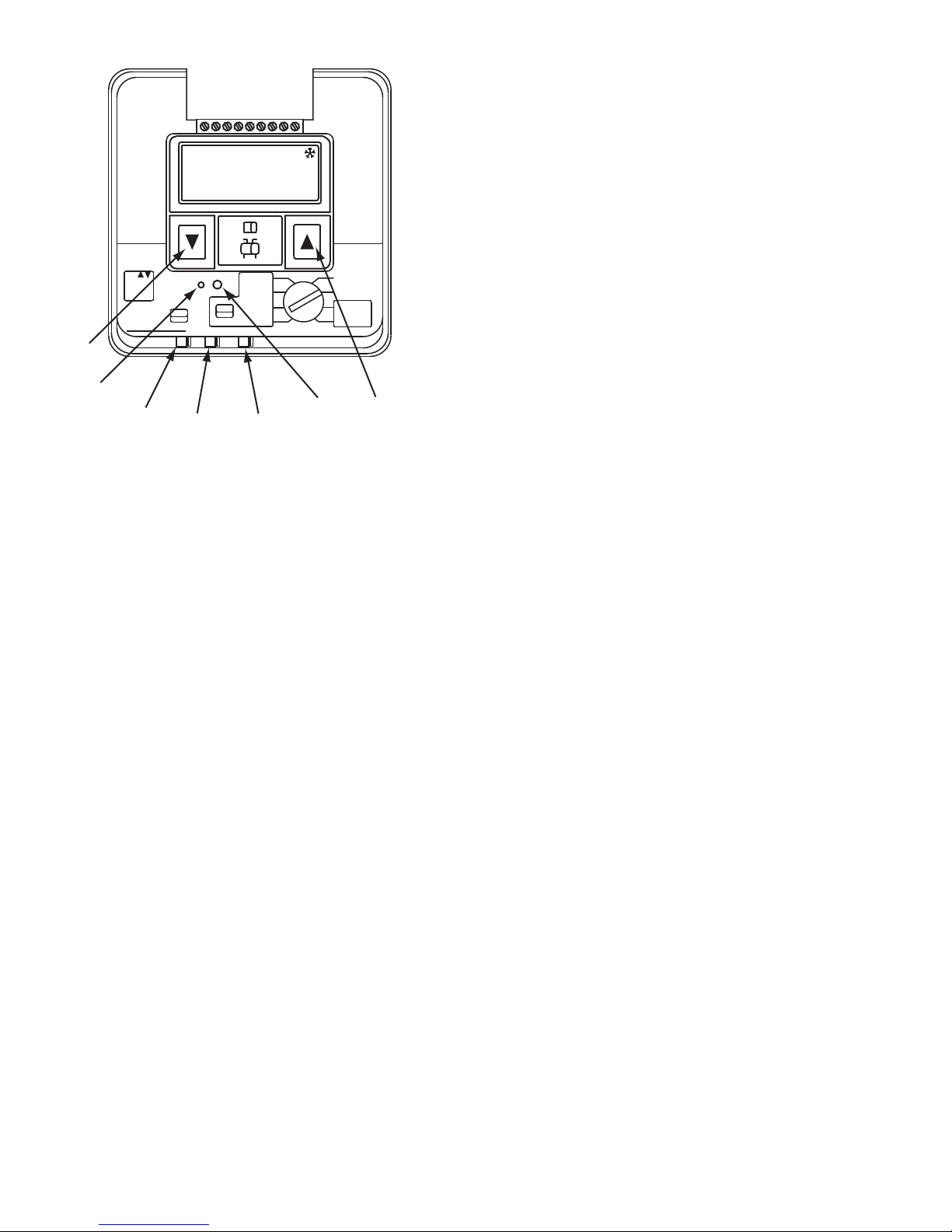
°F/°C
Jumper
Reset
Button
Down
Button
Display
Button
Backlight
Jumper
Up
Button
Reset
Disp
USE
BUTTONS
TO ADJUST
DISPLAY
LEAVE-RETURN
SCHEDULE 7 DAY
5 DAY TIME NOW
DAY NOW
RUN PROG
MANUAL
RETURN
SLEEP
WAKE
LEAVE
TIME
TEMP
PROGRAM SELECTION
EG
Manual
Actual
TEMP
FAN
ON FAN
AUTO
AUTO
COOL OFF
HEAT
72.3 F
0
Fan Mode
Jumper
This manual suits for next models
1
Table of contents
Other International Refrigeration Products Thermostat manuals


