INTERNATIONAL WELDING TECHNOLOGIES Lynx4 Quickshot User manual

Revision 2
1
Operating Instructions
Serial Number _______________
International Welding Technologies, Inc.
2650 Egg Harbor Road
Lindenwold, NJ 08021
(856) 435-8004 phone
(856) 435-4004 fax
www.internationalwelding.com

2
It is prohibited to transmit or reprint this document, as well as to utilize or disclose
its contents, unless this has been expressly granted by International Welding
Technologies, Inc. (herein also referred to as IWT). Non-compliance with this
regulation is liable to compensation. All rights reserved, particularly in the case
of a patent grant or GM registration.
We certify that the contents of this pamphlet correspond to the hard and software
described. Deviations, however, cannot be excluded, so that we cannot warrant
for absolute compliance. The data in this documentation, however, have been
verified regularly and necessary corrections will be incorporated in future
impressions. We appreciate any suggestions for improvement.
International Welding Technologies, Inc. – All rights reserved
Subject to technical alterations

Revision 2
3
Contents
1. General.......................................................................................................................5
1.1 Introduction to stud welding........................................................................................5
1.2 Application..................................................................................................................6
1.3 Information on the product..........................................................................................6
1.4 Serial Plate.................................................................................................................7
1.5 Information on documentation....................................................................................7
1.5.1 Information on operating instructions..................................................................7
1.5.2 Conduct in the case of malfunctions...................................................................8
1.6 Contacts and service address ....................................................................................8
2 Description of the stud welder................................................................................9
2.1 Capacitor discharge technology .................................................................................9
2.2 Stud welder set-up......................................................................................................10
2.3 Dimensions.................................................................................................................11
2.4 Technical Data............................................................................................................12
2.5 Block Diagram............................................................................................................13
3 Safety Instructions.....................................................................................................14
3.1 Description of reference signs in the operating instructions........................................14
3.2 Staff qualification and training.....................................................................................15
3.3 Dangers in case of non-compliance with safety instructions.......................................15
3.4 Safety-conscious working...........................................................................................15
3.5 Safety instructions for the operator/user.....................................................................16
3.6 The following should be observed before starting the system....................................16
3.7 Before starting to weld… ............................................................................................17
3.8 Safety precautions at installation site..........................................................................17
3.9 Working with the stud welder......................................................................................18
3.10 Safety instructions for maintenance, inspection and assembly works ......................18
3.11 Unauthorized retrofit and spare parts production......................................................19
3.12 Inadmissible operating methods...............................................................................20
3.13 Storing the stud welder.............................................................................................20
4 Installation of stud welder........................................................................................21
5 Initiation .......................................................................................................................22
5.1 Exterior components...................................................................................................22
5.1.1 Front view...........................................................................................................22
5.1.2 Rear view............................................................................................................22
5.2 Operating elements....................................................................................................23
5.3 Connection elements..................................................................................................23
5.4 Display elements........................................................................................................24

4
5.5 Fuse elements............................................................................................................25
5.6 Preparation for initiation..............................................................................................26
5.6.1 Ground connection .............................................................................................26
5.6.2 Connect stud welding pistol................................................................................26
5.6.3 Mains supply connection ....................................................................................26
5.7 Gun Setup .................................................................................................................27
5.8 Operation ...................................................................................................................29
5.9 Welding parameters....................................................................................................29
5.10 Reverse polarity........................................................................................................30
5.11 Quickshot circuitry ....................................................................................................30
6 Quality control............................................................................................................31
6.1 General.......................................................................................................................31
6.2 Demands on the company..........................................................................................31
6.3 Proof of qualification...................................................................................................31
6.4 Type and scope test ...................................................................................................31
6.4.1 Standard work test..............................................................................................31
6.4.2 Simplified work test.............................................................................................32
6.5 Test execution............................................................................................................32
6.5.1 Production of samples........................................................................................32
7 Maintenance...............................................................................................................33
7.1 Stud welder.................................................................................................................33
7.2 Replacement of components......................................................................................33
7.3 Fuses..........................................................................................................................33
7.4 Electronic Waste……………………………………………………………………………..34
8 Trouble shooting........................................................................................................35
8.1 Trouble shooting the LYNX4.......................................................................................35
8.2 Causes of poor or erratic welds..................................................................................35
8.3 Trouble shooting poor welds.......................................................................................36
9 Warranty……………………………………………………………………………………….37
Supplement for Insulation Welding....................................................................................38
Parts List............................................................................................................................42
Wiring Diagram..................................................................................................................47
Bill of Materials - Gun ........................................................................................................48

Revision 2
5
MORTAL DANGER
Persons with pacemakers must not operate the stud welder and must
not stay in the vicinity of the stud welder while it is running. Ensure
that the stud welder is not operated near electronically sensitive life-
supporting equipment, such as in intensive care units in hospitals.
1 General
1.1 Introduction to stud welding
Your new stud welding equipment is carefully constructed of the finest
components and materials available. Used properly, this equipment will
give you years of efficient service.
The system incorporates the latest in engineering advances, for
completely reliable end welding of mild steel, stainless steel, aluminum,
copper and lead free brass fasteners.
A careful study of this manual will enable you to understand how the
welder operates to insure proper performance under all operating
conditions.
You have purchased a product which:
•Conforms to machinery directives 2006/42/EC
•Conforms to low voltage directives 2006/95/EC
•Complies IEC 60974 for ARC welding equipment
•Conforms to IPC-A-610-Class II
•RoHS Compliant 2002/95/EC
Before putting the stud welder into operation, always observe the
following:
•Store the operating instructions in a place accessible to every
operator
•Ensure that the respective operator has read and understood the
operating instructions prior to installation. Each operator should
confirm this by signature
•Prevent the stud welder being operated by unauthorized persons
•Only trained personnel must operate the stud welder.

6
WARNING
Keep sufficient distance from electronic devices. When stud welding,
highly intensive electromagnetic fields are created which may
permanently damage these devises (e.g. television sets).
•Observe the safety instructions in Section 3.
•Call a doctor in case of an accident.
1.2 Application
The IWT stud welder LYNX4 Quickshot Stud Welding System allows you
to weld pins and threaded studs sizes #4 through 1/4” as well as various
fastening elements made of steel, stainless steel, aluminum, copper and
lead free brass.
The visible side of the work piece is spared to a large extent from
pressure marks or deformations, so that even thin sheet metals down to
0.060 thick retain their decorative appearance.
If you need consultation or assistance in solving problems, please
contact either our parent company or our field engineers.
1.3 Information on the product
Manufacturer: INTERNATIONAL WELDING TECHNOLOGIES, INC.
2650 Egg Harbor Road
Lindenwold, NJ 08021
Tel: 856-435-8004
Fax: 856-435-4004
Product Designation: LYNX4Quickshot Stud Welding System
Country of Origin: USA

Revision 2
7
1.4 Serial Plate
The serial plate is located on the rear side of the stud welder. It contains
information regarding the manufacturers name, address, country of
origin, product designation, method of welding, date of manufactured,
production number and main connection values.
1.5 Information on documentation
The following operating instructions are supplied with the LYNX4 stud
welder:
•Operating instructions for the LYNX4Quickshot Stud Welding
System
•1,2,3 Quick Setup Guide to Gap Welding
•LYNX4 Control PCB schematic
•LYNX4 fault indicator list
•LYNX4 Insulation Supplement
1.5.1 Information on operating instructions
The contents of these operating instructions are neither part of any
former or existing arrangement, pledge or legal relationship nor are
designed for modifying the latter. All obligations of INTERNATIONAL
WELDING TECHNOLOGIES, INC. result from the respective contract of
sale (invoice), which also comprises the complete and generally valid
warranties. These contractual warranty terms are neither extended not
restricted by the implementation of these operating instructions.
WARNING
Do not carry out any activities on the stud welding system without
specifically knowing the operating instructions or the respective part.
Ensure that only qualified personnel familiar with the operating
instructions and the necessary technical activities (training!) operate
the system.

8
1.5.2 Conduct in the case of malfunctions
If malfunctions occur, first try to detect and eliminate the causes
according to the list in Section 8 “Troubleshooting”. In all other cases,
contact our service department.
If you require service, please make sure that you supply the following
information:
•Customer number
•Product designation
•Serial number
•Year of construction
•Options
•Material of stud and work piece
•Stud dimensions
This information will help us both to save time and unnecessary costs,
e.g. caused by delivering the wrong spare parts.
1.6 Contacts and service address
If you have any questions regarding the operation of the stud welding
system, retrofits or if you require service, please contact your responsible
service office or the following address:
INTERNATIONAL WELDING TECHNOLOGIES, INC.
2650 Egg Harbor Road
Lindenwold, NJ 08021
Tel: 856-435-8004
Fax: 856-435-4004
www.internationalwelding.com

Revision 2
9
2 Description of stud welder
2.1 Capacitor discharge technology
The LYNX4Quickshot Stud Welding System with tip ignition operates
according to the principle of capacitor discharge as defined in the
American Welding Society Welding Handbook and in DVS Leaflet 0903
(German Welding Society). This system uses the abrupt discharge of a
capacitor bank to generate an electric arc.
Note the final picture in the sequence above; in order for a weld to be
good, it should have an even fillet completely around it. Any voids at all
indicate a weakness in the weld zone that could only cause weld failure
later. Also, the stud should appear to penetrate the parent material -- it
should never appear to be 'sitting on top' of the weld.
What actually happens during a capacitor discharge weld? The work
surface (or ground) is connected to one side of the capacitor bank. The
stud, through the collet, gun, and an electronic switching device (SCR) is
connected to the other side of the capacitor bank. When the stud is
placed against the work surface, only the tip touches. When the trigger is
squeezed, the switching device conducts, and the capacitor bank is
shorted out through the tip of the stud. Because of the high welding
current, the tip disintegrates and an arc is established. The arc melts the
interface surfaces, and the spring pressure of the gun combined with
velocity of the gun spindle movement pushes the stud into the parent
material to complete the weld. The process lasts about 1 - 3
milliseconds.
Stud tip or gun foot
touches work piece.
Stud lifts off and
drops under spring
pressure. Arc is
initiated
Stud immerses into
weld pool. Material
solidifies rapidly.

10
To make a good weld occur, two things are needed: heat and pressure.
A weld must have sufficient heat to melt the weld zone, and enough
pressure to provide good fusion.
In the LYNX4Quickshot Stud Welding System, heat is easily regulated
by the voltage on the capacitor bank. The length of weld cable used also
affects the heat. You should always use the supplied cables; otherwise
the weld arc is too erratic. Pressure is controlled by protrusion; the
amount of stud that extends beyond the gun's foot and the spring
pressure setting on the gun. It gap welding, adjustment made to the
spring will influence the velocity at which the stud is propelled to the
work. It should be mentioned that the more pressure the weld has, the
shorter the weld time will be. This will result in a cooler weld with less
penetration and less reverse side marking.
Besides heat and pressure, some of the other aspects of capacitor
discharge welding should be mentioned. Grounding is very important.
The ground connections must be clean and tight, but it must also be
positioned properly. Whenever the weld consistently "blows" to one side
(referred to as “arc blow”), the grounding is usually inadequate.
Another important subject is polarity. Straight polarity is when the work
surface is positive and the gun is negative. Whenever the work is clean,
straight polarity is used. On the other hand, reverse polarity (work
surface is negative) is used for welding brass or whenever impurities
such as galvanizing are present (see Section 5.9 for a discussion of
polarity).
2.2 Stud welder set-up
The standard pistol to be connected to the LYNX4Quickshot Stud
Welding System is the IWT-G1 gap gun or IWT-C1 contact gun. See
additional information on the weld guns in Section 5.

Revision 2
11
2.3 Dimensions
The LYNX4Quickshot Stud Welding System is a powerful but lightweight
system that is easily carried into the work place. The base unit weighs
20 lbs. The dimensions are:
12” Wide x 12” Long x 5” High
12”
5”
12”

12
2.4 Technical Data
Description LYNX4Quickshot Stud Welding System
Welding range #4/12ga through 1/4”
Material Steel, Stainless Steel, Aluminum, Copper,
Lead Free Brass
Welding Method Capacitor Discharge Tip Ignition
Standard Pistol(s) IWT-G1 gap, IWT-C1 contact or IWT-Ci
insulation gun
Current Source Capacitor Bank
Charging Capacity 54,000 micro Farad
Charging Voltage 50 – 195 V adjustable
Welding Time 0.001 – 0.003 seconds
Welding Duty Cycle Up to 20 studs per minute
Mains Supply 110 or 220 VAC 50/60 Hz. Switchable on the
main board
Fuses 2 x 16A slow blow, 250 V
Welding Cable #2 highly flexible weld cable
Ground Cables Two, #2 highly flexible weld cable
Weight 24 lbs
Color Blue
Subject to technical change without notice.
Revision 2
13
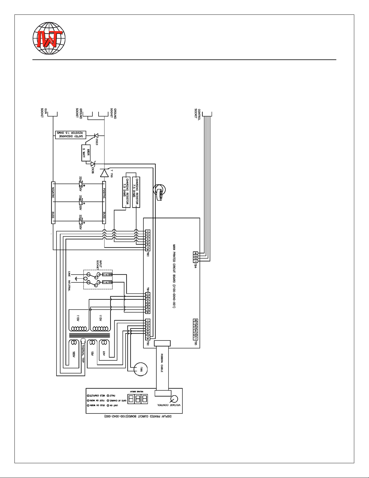
2.5 Block Diagram
14
3 Safety instructions
These operating instructions contain basic instructions that have to be
complied with during installation and/or operation. It is therefore
absolutely necessary that the operator and responsible specialist staff
read these operating instructions prior to assembly and initiation. They
must always be available at the installation site.
Not only the general "safety instructions" listed under this main item, but
also the special safety instructions e.g. for high temperatures, voltages,
etc. listed under the other main items have to be complied with.
3.1 Description of reference signs in the operating instructions
The non-observance of safety instructions can cause damage to the
operator and observers. The safety instructions of this manual are
marked with the general symbol for danger safety symbol in
compliance with DIN 4844-W9
Warning of electrical voltage is specifically marked with the safety
symbol in compliance with DIN 488-W8.

Revision 2
15
In addition to these symbols, the words “DANGER TO HEALTH” or
“MORTAL DANGER” refer to the degree of a possible danger.
Safety instructions the non-observance of which may endanger the
machine and its functions are marked with the terms
"CAUTION" or "WARNING".
General instructions are marked with the hand symbol.
3.2 Staff qualification and training
The staff responsible for operation, maintenance, inspection and
assembly must have the respective qualification for carrying out these
works. Field of responsibility, competence and the supervision of staff
has to be exactly regulated by the user. If your personnel do not have the
necessary knowledge they must be trained and instructed. If necessary,
this can be done by the manufacturer/supplier on behalf of the welding
equipment user. Furthermore, the user must ensure that the contents of
the operating instructions are fully understood by the staff.
3.3 Dangers in the case of non-compliance with safety instructions
The non-compliance with safety instructions may not only endanger
persons, but also the welding system and its environment. Any non-
compliance with safety instructions may result in a complete loss of
damage claims.
Non-compliance with safety instructions may have the following conse-
quences:
•Failure of important system functions
•Failure of prescribed methods for maintenance
•Danger to persons through electric, mechanic, thermal and
acoustic influences
3.4 Safety-conscious working
The safety instructions listed in this manual, existing national accident
prevention regulations and possible international working, operating and
safety regulations of the user must be complied with.

16
MORTAL DANGER
Persons with pacemakers must neither operate the stud welder nor
stay near it.
MORTAL DANGER
When welding, do not wear clothes soiled with easily combustible
substances such as oil, gasoline and thinners, etc.
3.5 Safety instructions for the operator/user
When stud welding, danger may result from
•electric current
•optical radiation
•harmful substances (smoke)
•acoustic shock
•spraying sparks
You are therefore obliged to restrict the dangers to an inevitable degree
and to point these dangers out to the operator and other persons
involved.
3.6 The following should be observed before starting the system...
Before starting the system, pay attention to the following information:
•Do not touch live electrical parts.
•Juveniles under the age of 16 years must not operate the stud
welding system.
•Read all of the operating instructions before starting the system.
•Only qualified personnel are allowed to operate the system.
•Prevent unauthorized use of the system by children or
unqualified personnel
•Wear non-combustible, closed working clothes.
•Wear a leather apron to protect your clothes from welding
spatters that are generated during the welding process.
•Wear head protection when carrying out welding work above
your head

Revision 2
17
•Wear gauntlet gloves made of leather.
•Never wear rings, watches or electrically conductive jewelry.
•Wear protective goggles to protect your eyes from welding
spatters and flashes of light that are generated during the
process.
•Wear ear protection. Capacitor discharge generates a loud bang.
•Disconnect input power before installing or servicing this
equipment according to OSHA 29 CFR 1910.147
•Turn off all equipment when not in use.
•Do not use worn, damaged, undersized or poorly spliced cables.
•Do not drape cables over your body.
•Welding on closed containers, such as tanks, drums, or pipes
can cause them to blow up. Sparks can fly off from the welding
arc. The flying sparks, hot work pieces, and hot equipment can
cause fires.
3.7 Before starting to weld...
•Check the state of all cables.
•Immediately replace defective cables and cable connections.
•Ensure that the air apertures of the housing are not covered.
Heat accumulation may damage the stud welder.
•Look around for potential safety or fire hazards.
3.8 Safety precautions at installation site
•When placing the stud welder on tables or similar workshop
furniture, ensure that the stud welding system stands firmly and
that the table can bear its weight.
•Make sure mains socket and stud welder are properly grounded.
•Comply with fire prevention regulations and do not weld in
hazardous locations.
•Make sure room is well ventilated or extract welding fumes, if
necessary.

18
DANGER TO HEALTH
When welding, fumes and suspended matters may be generated.
Beware of fumes detrimental to health, particularly when using
surface-treated materials. If possible, only weld in rooms that are
higher than 10 ft. As per VBG 15, special regulations are applicable
for narrow rooms.
One of the accident prevention regulations
applicable for stud welders is VBG15 "Welding, cutting and similar
working methods". For more information, contact the Employer's
Liability Insurance Association.
DANGER TO HEALTH
When welding, do not wear clothes soiled with easily combustible
substances such as oil, grease and paraffin oil, etc.
3.9 Working with the stud welder
•Comply with all accident prevention regulations which apply to
the operation of your stud welder
If an accident happens,
•switch off the stud welder and disconnect it from the mains supply
•call a doctor

Revision 2
19
Only carry out maintenance
works when stud welder has
been switched off and
unplugged—follow
lockout/tagout procedures.
3.10 Safety instructions for maintenance, inspection and assembly works
The user must ensure that all maintenance, inspection and assembly
work is carried out by authorized and qualified technical personnel.
Generally, only work on the system when it has been switched off and
after having disconnected it from the mains supply. It is necessary to
comply with the procedure for stopping the stud welding system
described in the operating instructions (chapter 3.13).
Immediately after having completed your work, re-install and activate all
safety and protective devices.
3.11 Unauthorized retrofit and spare parts production
The system may only be retrofitted and modified after consultation with
the manufacturer. Original spare parts and accessories authorized by the
manufacturer guarantee safety. The use of other parts may result in the
cancellation of warranty for any consequences thus caused.

20
Limit values
3.12 Inadmissible operating methods
Working safety of the stud welding system supplied can only be
guaranteed when the stud welder is used in accordance with its purpose.
The limit values indicated in the chapter "Technical data" must never be
exceeded.
3.13 Storing the stud welder
•Switch off the mains switch (chapter 5.1.2, item 8) located at the stud
welder's rear side.
•Disconnect the mains plug from the socket.
•Disconnect:
- the ground cables (chapter 5.1.1 , item 4)
- the control cable (chapter 5.1.1, item 6)
- the welding cable (chapter 5.1.1, item 5)
from the stud welder.
•Roll up the cables without buckling them.
•Make sure stud welder cannot be used by unauthorized persons.
•Check the welding cable and connections of the stud welder for
damage such as burn-off, mechanical wear etc. and have damaged
parts replaced by IWT customer service.
Table of contents
Other INTERNATIONAL WELDING TECHNOLOGIES Welding System manuals

Popular Welding System manuals by other brands


Kemppi
Kemppi Master S 400 Service manual

Forney
Forney Easy Weld 180 ST operating manual

Lincoln Electric
Lincoln Electric Invertec V155-S Service manual

Parkside
Parkside PESG 120 A1 Operation and safety notes

Tweco
Tweco PullMaster PMP3333545 Safety and operating instructions

TOOL WAREHOUSE
TOOL WAREHOUSE SG-8900 manual