Interra ITR901-001 User manual

@2019 INTERRA PM190205012AEN
ITR901-001 –KNX IP ROUTER
Product Manual

KNX IP Router
Product Manual
2
@2019 INTERRA PM190205012AEN
Information contained in this publication regarding
device applications and the like is provided only for
your convenience and may be superseded
versions by updates. It is your responsibility to
ensure that your application meets with your
specifications.
INTERRA MAKES NO REPRESENTATIONS OR
WARRANTIES OF ANY KIND WHETHER
EXPRESS OR IMPLIED, WRITTEN OR ORAL,
STATUTORY OR NONSTATUTORY, RELATED
TO THE INFORMATION INCLUDING BUT NOT
LIMITED TO ITS CONDITION, QUALITY,
PERFORMANCE, MERCHANTABILITY OR
FITNESS FOR PURPOSE.
Interra disclaims disclaims all liability arising from
this information and its use. Use of Interra devices
in life support and / or safety applications is entirely
at the buyer’s risk, and the buyer agrees to defend,
indemnify and hold harmless Interra from any and
all damages, claims, suits, or expenses resulting
from such use. No licenses are conveyed, implicitly
or otherwise under any Interra intellectual rights.
Trademarks
The Interra name and logo and the Interra ITR901–
001 KNX IP Router are registered trademarks of
Interra Technology in Turkey and other countries.
All other trademarks mentioned herein are property
of the Interra Technology.
© 2019, Interra, Printed in Turkey, All Rights
Reserved.
Printed on recycled paper.
TS EN ISO 9001:2008

KNX IP Router
Product Manual
3
@2019 INTERRA PM190205012AEN
TO OUR CUSTOMERS
One of our most important aims is to provide you with the best documentation possible to use
successfully your Interra products. Focusing of this, we will keep on improving our documentation to
better suit your needs. Our publications will be updated as new volumes as soon as changes are
introduced.
If you have any questions or comments regarding this publication, do not hesitate to contact us:
E-mail: [email protected]om.tr
Tel: +90 (216) 326 26 40 Fax: +90 (216) 324 25 03
Most Current Product Manual
To obtain the most up-to-date version of this product manual, please visit our Web site at:
http://www.interra.com.tr
You can determine the version of an Interra document examining its literature number found on the
bottom right corner of any page.
The first two letters of the literature are the type of document. The numbers that follow are the creation
date of the document and the last letter is the version (e.g., PM181017001A is the version A of a
product manual created on the date 17/10/18.)

KNX IP Router
Product Manual
4
@2019 INTERRA PM190205012AEN
CONTENTS
1.) PRODUCT DESCRIPTION ............................................................................................................................... 6
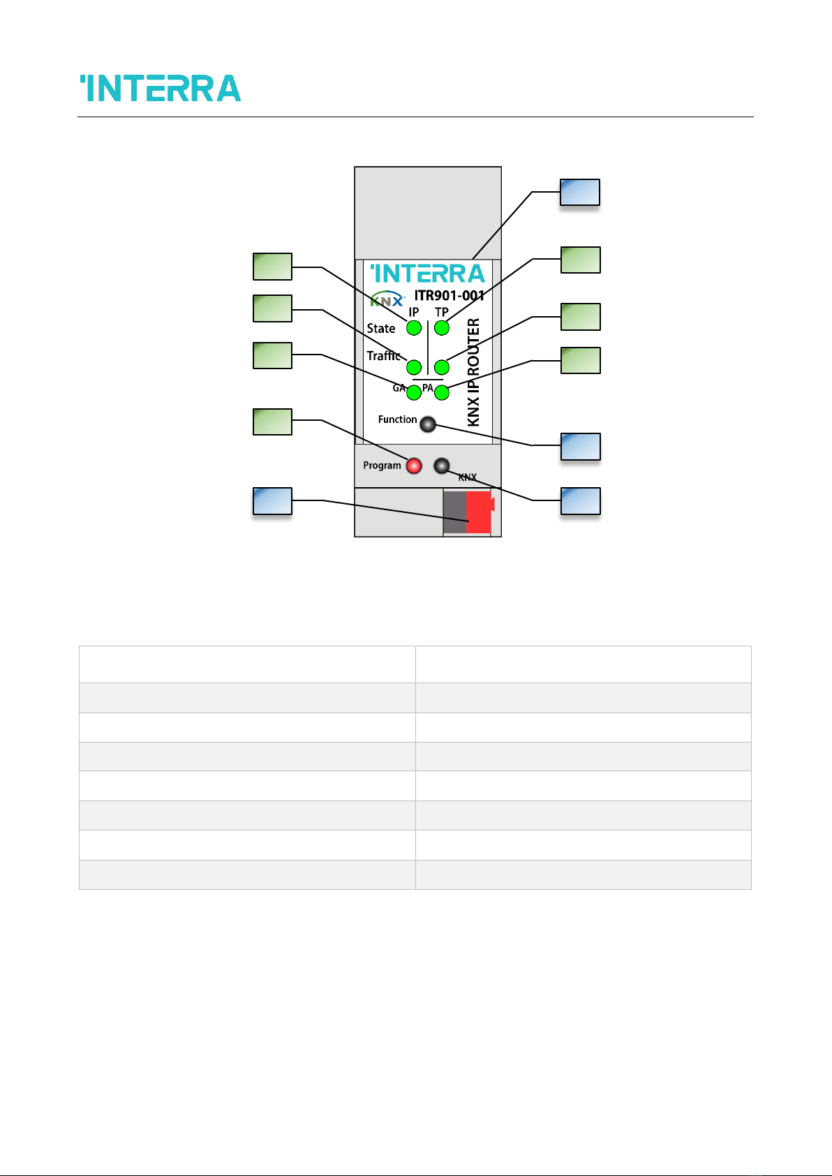
1.1.) Front Panel ................................................................................................................................................ 7
1.2.) LED Indicators............................................................................................................................................ 8
1.3.) Device Commissioning............................................................................................................................... 9
1.4.) General Features....................................................................................................................................... 9
2.) KNXNET / IP ................................................................................................................................................ 10
2.1) IP Tunnelling............................................................................................................................................. 10
2.3) IP Routing ................................................................................................................................................. 10
2.4) IP Bootloader / Boot Mode ...................................................................................................................... 11
3.) OPERATIONAL DESCRIPTION...................................................................................................................... 11
3.1) IP Coupler Application.............................................................................................................................. 11
3.2) IP Network................................................................................................................................................ 11
3.3) KNX Network Installation: ........................................................................................................................ 13
3.4) Programming............................................................................................................................................ 14
3.4.1) Physical Address Assignment ................................................................................................................ 14
3.5) Function Button........................................................................................................................................ 15
3.5.1) Manual Function ................................................................................................................................... 15
3.5.2) Restore Factory Settings........................................................................................................................ 15
3.5.3) Boot Mode Activation ........................................................................................................................... 15
3.5.4) LED Status Display ................................................................................................................................. 16
4.1) Genel ........................................................................................................................................................ 17
4.1.1) Parameters List...................................................................................................................................... 17
4.2) IP Configuration........................................................................................................................................ 18
4.2.1) Parameters List...................................................................................................................................... 18
4.3) KNX Multicast Address ............................................................................................................................. 19
4.4) Main Line (IP)............................................................................................................................................ 20
4.5) Subline (KNX TP)....................................................................................................................................... 21
5.) WEB FRONT-END........................................................................................................................................ 22
5.1) Accessing the Device Web Front-End....................................................................................................... 22
5.1.1) Access via Windows Network UPnP...................................................................................................... 23
5.1.2) Access via IP Address............................................................................................................................. 23
5.1.3) Access via MAC Address........................................................................................................................ 23
5.2) Device Info................................................................................................................................................ 24

KNX IP Router
Product Manual
5
@2019 INTERRA PM190205012AEN
5.3) KNX ........................................................................................................................................................... 24
5.4) Firmware Update & Boot Mode............................................................................................................... 25
5.5) IP Tunnelling Address Assignment ........................................................................................................... 27
6.) TECHNICAL DRAWINGS .............................................................................................................................. 29

KNX IP Router
Product Manual
6
@2019 INTERRA PM190205012AEN
1.) PRODUCT DESCRIPTION
The ITR901-001 Interra KNX IP Router works as a KNX line/area coupler to provide a bi-directional data connection between
KNXnet/IP line (main line) and KNX TP line (subline). KNX IP and KNX TP are coupled having a galvanic isolation in
between. The flexible ITR901-001 can be used as a KNX TP line coupler to connect several KNX TP lines but also as a KNX
TP area coupler to connect several TP areas or different KNX TP installation systems via an IP Backbone/Ethernet/Internet.
Telegram filtering is accomplished according to the installation place in the hierarchy (Physical Telegrams) and according
to the built in filter tables for group communication (Group Telegrams). For detailed diagnosis all operational modes/states
are shown by a duo-LED display.
With the ETS (or compatible commissioning tool) ITR901-001 also works as the KNX programming interface having no
KNX communication objects for itself. Connecting a personal computer to the KNX TP bus can ideally be done via
Ethernet/Internet. For Tunnelling and Routing up to four tunnelling addresses can be used. To ease commissioning and
troubleshooting the Manual Function for short-time telegram filter switch-off and special routing/repetition/confirmation
settings are available. A comfortable Web front-end to watch the busload history, to identify ITR901-001device in a
network and to update the firmware via IP is provided.

KNX IP Router
Product Manual
7
@2019 INTERRA PM190205012AEN
1.1.) Front Panel
Fig 1: Front View of Device
LED
BUTTON / CONNECTOR
1. State IP (Main Line)
A. Ethernet Connector
2. Bus State KNX TP (Subline)
B. Function Button
3. Telegram Traffic IP (Main Line)
C. Program Button
4. Telegram Traffic KNX TP (Subline)
D. KNX TP Connector
5. Group Address(GA) Routing (0....13)
6. Physical Address(PA) Routing
7. Programming
Tablo 1 : LEDs and Buttons Definitions
In the above figure, a front view of the device is shown. Also, the table 1 shows the indicators and features on the device.
A
2
B
C
D
4
6
1
3
5
7

KNX IP Router
Product Manual
8
@2019 INTERRA PM190205012AEN
1.2.) LED Indicators
NUMBER
LED
COLOUR
DESCRIPTION
1
State IP(Main Line)
Green
IP line OK.
Red
Manual Function active.
Off
No IP connection.
2
Bus State KNX TP
(Subline)
Green
Subline OK.
Off
Subline not connected.
3
Telegram Traffic IP
(Main Line)
Blinking Green
Telegram traffic extent indicated by blinking.
(Speed up to 10Mbit/s)
Blinking Red
Transmission error.
Off
No telegram traffic.
4
Telegram Traffic KNX
TP
(Subline)
Blinking Green
Telegram traffic extent indicated by blinking.
Blinking Red
Transmission error.
Off
No telegram traffic.
5
Group Address Routing
Green
Filter table active.
Orange
Route all.
Red
Block all.
Off
Routing of Group Telegrams is different on main
line and subline.
6
Physical Address
Routing
Green
Filtering active.
Orange
Route all.
Red
Block all.
Off
Routing of Physical Telegrams is different on main
line and subline.
7
Programming
Red
Program Mode / Boot Mode active.
Blinking Red
No IP connection.
Off
Program Mode / Boot Mode not active.
Note: If the device is used as IP Router without physical address x.y.0, the "physical address routing" named LED 6 (PA)
works not like described at table 1.

KNX IP Router
Product Manual
9
@2019 INTERRA PM190205012AEN
1.3.) Device Commissioning
The default settings of the device are :
➢All telegrams are blocked due to the filter table is not defined.
➢The Manual Function switch-off time is 120 min.
➢Physical address is “15.15.0”.
➢Never connect the device to 230 V.
Fig 2: Connection Scheme
1.4.) General Features
➢ITR901-001 KNX IP Router supports extended frames and long telegrams up to 240 bytes APDU length.
➢ITR901-001, favourably replaces a common TP line/area coupler. The great advantage is using KNX IP as a fast
KNX backbone medium (for sending telegrams between lines and areas).
➢ITR901-001 works without external power supply.
➢Providing IP Tunnelling to the ETS connection interface (also other tools to enable commissioning and monitoring)
the additional tunnelling addresses are not the same used for ETS connection. Four different tunnelling
connections with a separate address for each can be realized in parallel.
➢ACK sending on sent out messages is ETS configurable.
➢When there is no IACK response on the subline the Interra KNX IP Router is able to repeat messages up to three
times. Repetitions can be configured for both Physical Telegrams and Group Telegrams via ETS (to ease
Ethernet
KNX TP

KNX IP Router
Product Manual
10
@2019 INTERRA PM190205012AEN
troubleshooting). After an IACK response no repetition is following and the negative IACK/BUSY failure mechanism
is maintained.
➢Automatic function for switching back to run-time telegram filtering after configurable suspension period. This
avoids forgetting the reactivation of filtering.
➢For an ETS configurable time period, it is possible to switch off telegram filtering by only pressing a button on the
device front panel. Without additional ETS download filtering is suspended. This is necessary for running fast
diagnostics on site.
➢Temporarily suspending telegram filtering eases commissioning and debugging. Without ETS download temporary
access to other lines becomes possible.
➢UPnP is available to discover the device within the IP network. This can only be realized by a proper network
installation in terms of topology. With use of KNXnet/IP ETS is able to recognize the communication interface
device.
➢Updating the firmware can easily be accomplished by a Web browser. The available Web front-end provides
informative settings and enables to switch the device into Program Mode without use of the Program Button.
➢In networks with high busload the internal amount of communication buffers are capable of smoothing peeks in the
communication load course.
➢ITR901-001 device’s ETS database entries are available for ETS4 and later.
➢ITR901-001 supports KNXnet / IP, ARP, ICMP, IGMP, HTTP, UPnP, UDP/IP, TCP/IP, DHCP and AutoIP.
2.) KNXNET / IP
ITR901-001 is a KNX IP router and KNX IP routers are highly similar to TP line couplers. The only difference is that they use
the IP communication medium as main line and the KNXnet/IP communication protocol. However, KNX end devices can be
integrated directly via IP. This makes the Ethernet a real KNX medium.
As documented in the KNXnet/IP protocol specifications, KNX telegrams can also be transmitted encapsulated in IP
telegrams. Ethernet networks as well as Internet can be used to route or tunnel KNX telegrams. In this way, IP interfaces
and IP routers are an alternative to USB data interfaces and TP line/area/backbone couplers. In the latter case, the normal
TP backbone is replaced by a fast Ethernet based line.
2.1) IP Tunnelling
The presence of the Internet Protocol (IP) has led to the definition of the KNXnet/IP protocol. KNXnet/IP offers the possibility
for point-to-point connections for the ETS (KNXnet/IP Tunnelling) and/or between supervisory system and KNX installation.
The KNXnet/IP device management enables KNXnet/IP device configuring via the KNX network in order to reduce the time
required for complete network configuration.
2.3) IP Routing
IP Routing is the way of interconnecting KNX lines and areas by IP network(s) via KNXnet/IP. In IP networks the KNXnet/IP
Routing defines the way of KNXnet/IP router communication.

KNX IP Router
Product Manual
11
@2019 INTERRA PM190205012AEN
2.4) IP Bootloader / Boot Mode
The IP bootloader function is used to completely rewrite the flash memory content and is not just a simple application
download. Both communication stack and application software are downloaded. The download tool is a separate tool
independent from ETS.
The firmware update procedure via IP is executed by a Web front-end and makes use of special messages to speed up the
process. To be protected, their contents are encrypted.
Note : Entering Boot Mode is equivalent to activating the IP bootloader function.
3.) OPERATIONAL DESCRIPTION
In network installations ITR901-001 can be used as KNX IP area coupler or KNX IP line coupler. With its default settings the
device operates as is supposed to.
3.1) IP Coupler Application
When ITR901-001 receives telegrams (for example during commissioning) that use physical addresses as destination
addresses, it compares the physical addresses of the receiver with its own physical address and decides on that whether it
has to route the telegrams or not.
When ITR901-001 receives telegrams that use group addresses as destination addresses, it reacts in accordance with the
parameter settings. During normal operation (with default settings), ITR901-001 only routes telegrams whose group
addresses are entered in the filter table.
If ITR901-001 routes a telegram and does not receive an acknowledgement, or if a bus device discovers a transmission
error, the coupler repeats telegrams up to three times (depending on the corresponding parameter that is set by ETS). With
the parameters „Repetitions if errors...“, this function can be set separately for each line. It is recommended to use the default
parameter setting.
IP Coupler is designed for use in 10/100 BaseT networks compliant to IEEE802.3. The AutoSensing function sets the baud
rate (10 Mbit or 100 Mbit) automatically. IP address can be received from a DHCP server. For this, the ETS automatic
assignment setting of the IP address is required. If no DHCP server is found by this setting device starts an AutoIP procedure
and autonomously assigns the IP address. The IP address that ITR901-001 receives during its start-up (via DHCP or AutoIP)
is retained until next start-up (e.g. due to power off or reprogramming). If the IP address of the device is supposed to have a
fixed assignment a fixed IP address (as well as subnet mask and standard gateway) can be set by ETS.
Note : ETS does not provide an unload procedure for applications.
3.2) IP Network
ITR901-001 sends telegrams from/to the TP network to/from the IP network in accordance with the KNXnet/IP protocol
specification. According to the default setting these telegrams are sent as multicast telegrams to the multicast IP address
224.0.23.12 port 3671. The multicast IP address 224.0.23.12 is the defined address for the KNXnet/IP by KNX Association
in conjunction with the IANA. It is recommended to use this default address as defined. Only if it becomes necessary due to
the existing network, the address can be changed as shown in chapter 4.3 KNX Multicast Address.

KNX IP Router
Product Manual
12
@2019 INTERRA PM190205012AEN
Key Notes :
➢All KNX IP devices that are intended to communicate with each other via IP must have the same IP multicast
address.
➢Multicast IP address 224.0.23.12 may need to be changed in respect of the network type and of the network
components´ settings.
➢IGMP (Internet Group Management Protocol) is used for IP configuration to establish multicast group belonging.
➢If the IP address is changed from the IP side it may happen that ETS does no longer recognize the device and
connection cannot be maintained (tunnelling uses IP addresses).
➢It is recommended to trigger a restart and to change IP addresses only from TP side.
➢If problems occur for IP address assignment please ask your network administrator.
➢According to the topology, the Tunnelling addresses always have to be assigned in the range of subline addresses.
For more information about additional physical addresses for tunnelling please check the section 5.5.
➢Programming devices of another line different to which the device used for (re)programming is connected the use
of a correct topology is mandatory.

KNX IP Router
Product Manual
13
@2019 INTERRA PM190205012AEN
3.3) KNX Network Installation:
For line coupler functionality in a KNX network the ITR901-001 device has to use the correct physical address of a line
coupler (X.Y.0, 1≤X & Y ≤15). In ETS up to 225 addresses can be defined (from 1.1.0 to 15.15.0). For area coupler
functionality in a KNX network ITR901-001 has to use the correct physical address of an area coupler (X.0.0, 1≤X≤15). In
ETS up to 15 areas can be defined.
If ITR901-001 is used in a KNX system for both purposes, it is only necessary to ensure that the ITR901-001 used as a line
coupler has a line coupler address assigned from a free addressing area. Following figure illustrates the ITR901-001 router
topology for KNX lines and KNX areas.
Fig 3: Interra KNX IP Router Network Topology
Example: If an IP router with address 1.0.0 already exists on the backbone no IP router with address 1.X.0, 1≤X≤15 can be
added here. Even if no line coupler with address 1.1.0 exists on the subline of the 1.0.0 IP coupler. Vice versa, if a line
coupler with address 1.1.0 already exists in the installation no IP router with address 1.0.0 can be added.
IP Backbone
TP Line
TP Area
TP Area
1.0.0
1.X.0
2.0.0
3.1.0
1.1.0
1.2.0
Main Line
Subline
Subline

KNX IP Router
Product Manual
14
@2019 INTERRA PM190205012AEN
3.4) Programming
To download the desired physical address or an ETS setting the Program Button must be pressed first. Successive pressing
the Program Button will turn on and off the Program Mode. LED 7 lighting in red colour indicates Program Mode is active.
When Program Mode is active ETS recognizes the device of interest for downloading.
Not: A blinking red Programming LED indicates that the Ethernet cable is not connected properly.
Not: Even when Boot Mode is active successive pressing the Program Button will turn on and off Program Mode and
Programming LED.
3.4.1) Physical Address Assignment
To commission the ITR901-001 Interra KNX IP Router device an interface connection (IP, USB) to the KNX bus system is
required. The device is supplied with the individual physical address 15.15.0. The KNX product database entry(available for
ETS4 and higher) can be downloaded from the Interra web site and from the KNX Online Catalog.
With the ETS the physical address can be assigned to the device by setting the desired address in the properties window of
the ETS. After starting the ETS download and then pressing the Program Button the device restarts itself.
Fig 4: ETS Properties Window
Note: The term “physical address” means the KNX physical address as well as the ETS individual address. Both terms are
used by the KNX organisation interchangeably.

KNX IP Router
Product Manual
15
@2019 INTERRA PM190205012AEN
3.5) Function Button
The Function Button activates the ITR901-001’s special functions Manual Function, Factory Reset and Boot Mode. When
the function button is pressed, special functions to be used depend on time / number / status.
3.5.1) Manual Function
A rather short press (≈ 3 sec) of the Function Button activates the Manual Function during normal operation. With a second
short button press it can be deactivated before the Manual Function Switch-off time is expired.
When the Manual Function is active either all Physical Telegrams or all Group Telegrams or both pass the device without
filtering.
After the Switch-off time period has elapsed ITR901-001 automatically switches back to normal operation. To configure the
Manual Function and set the Switch-off time use the parameter tab General like shown in chapter 4.1 General. After
switching back from Manual Function to normal operation the latest downloaded parameter setting / filter table entries are
active again.
3.5.2) Restore Factory Settings
A long press (≈ 15 sec) of the Function Button soon followed by a second press for some seconds executes the Factory
Reset. After the first press the LED display lights different (see table 3). After the second press all parameters will be set to
factory default (incl. physical address). Subsequently, LEDs show the normal display again.
When Boot Mode is active the Function Button executes the Factory Reset in a different way. After pressing the Button for
about five seconds the LEDs light with green colour. After second press (about two seconds) the parameters will be set to
factory default (includes physical address) and LEDs again display Boot Mode is on.
3.5.3) Boot Mode Activation
For Boot Mode activation the firmware update process must be executed. During the process, the Function Button must be
pressed to enter Boot Mode (see chapter 5.4). The numbers in the tables shown below are based on Table 1.

KNX IP Router
Product Manual
16
@2019 INTERRA PM190205012AEN
3.5.4) LED Status Display
NUMBER
LED
COLOUR
DESCRIPTION
1
State IP
Orange
Lights red if not connected.
2
Bus State KNX TP
Green
5
Group Address Routing
Orange
6
Physical Address
Routing
Orange
Table 2 : LED Status Display for Manual Function
NUMBER
LED
COLOUR
DESCRIPTION
1
State IP
Orange
Lights red if not connected.
2
Bus State KNX TP
Orange
5
Group Address Routing
Orange
6
Physical Address
Routing
Orange
Table 3 : LED Status Display for Factory Reset After First Button Press
NUMBER
LED
COLOUR
DESCRIPTION
1
State IP (Main Line)
Green
2
State KNX TP
(Subline)
Blinking Green
3
Telegram Traffic IP
(Main Line)
Blinking Green
not the same tempo as LED2.
7
Programming
Red
Table 4 : LED Status Display for Boot Mode

KNX IP Router
Product Manual
17
@2019 INTERRA PM190205012AEN
4) ETS DATABASE PARAMETERS
All images described in this chapter are retained from the relevant ETS configuration pages of the ITR901-001. The device
database file is compatible with ETS4 and later versions.
4.1) Genel
If the host name is changed by a download in ETS4, a manual device restart (bus disconnection, reset of the line etc.) is
recommended to take over this change.
Fig 5 : General Page Parameters
4.1.1) Parameters List
PARAMETER
DESCRIPTION
VALUES
Host name
Field to enter the device name providing
an easy search of the device by ETS, by
Windows Network and by KNXnet/IP
visualisation systems.
30 Characters allowed
(KNX IP Router)
Slow tunnelling connections
support
Enable to support slow tunnelling
connections.
yes
no
Switch-off time for Manual
Function
After expiry of this time period the
Manual Function is switched off
automatically.
10 mins
1 hour
4 hours
8 hours
Manual Function
Configuration setting for telegram routing
when the Manual Function is active.
disabled
dass all telegrams
pass all Physical address telegrams
pass all Groups address telegrams
pass all telegrams

KNX IP Router
Product Manual
18
@2019 INTERRA PM190205012AEN
4.2) IP Configuration
After an ETS download IP addresses are not updated. It is essential to execute a manual device restart(bus disconnection,
reset of the line) to get IP configuration data updated.
Fig 6 : IP Configuration Tab Parameters
4.2.1) Parameters List
PARAMETER
DESCRIPTION
VALUES
HTTP Port
Select one of the two official system ports.
80
8080
DHCP
If DHCP is used, no further IP parameters have to
be set.
do not use
use
IP address*¹
Due to each part is 1 byte, the values should be
adjusted by entering between 0 and 255.
0-255.0-255.0-255.0-255
[0.0.0.0]
Subnet mask*¹
Due to each part is 1 byte, the values should be
adjusted by entering between 0 and 255.
0-255.0-255.0-255.0-255
[0.0.0.0]
Default gateway*¹
Due to each part is 1 byte, the values should be
adjusted by entering between 0 and 255.
0-255.0-255.0-255.0-255
[0.0.0.0]
DNS server*¹
Due to each part is 1 byte, the values should be
adjusted by entering between 0 and 255.
0-255.0-255.0-255.0-255
[0.0.0.0]
*¹This parameter, is only visible when the “DHCP”parameter is set to “do not use”.

KNX IP Router
Product Manual
19
@2019 INTERRA PM190205012AEN
4.3) KNX Multicast Address
For KNXnet/IP the multicast address “224.0.23.12”is the defined address from KNX Association in conjunction with IANA.
Change this address only if it becomes necessary due to the existing network.
Make sure that during commissioning all KNX IP devices intended to communicate with each other via IP use the same
multicast address. After downloading a new multicast address a manual restart has to be executed.
Fig 7 : KNX Multicast Address Parameter Page
PARAMETER
DESCRIPTION
VALUES
System multicast
System default multicast address is
“224.0.23.12”. If system multicast is not used the
multicast address has to be defined manually.
do not use
use
Byte 1*¹
If system multicast address is used “224” is set
permanently. Otherwise “239”is set permanently.
224(System)
239
Byte 2*¹
Set manually if system multicast address is not
used.
0 (0-255)
Byte 3*¹
Set manually if system multicast address is not
used.
0 (0-255)
Byte 4*¹
Set manually if system multicast address is not
used.
0 (0-255)
*¹This parameter, is only visible when the “System multicast” parameter is set to “do not use”.

KNX IP Router
Product Manual
20
@2019 INTERRA PM190205012AEN
4.4) Main Line (IP)
For Group Telegrams and Physical Telegrams the setting “transmit all” is intended only for testing purposes. Please do not
use for normal operation.
Fig 8 : Main Line (IP) Parameter Page
PARAMETER
DESCRIPTION
VALUES
Telegram routing
block: No telegrams are routed.
filter: Telegrams entered in the filter table are
routed.
route: All telegrams are routed.
configure: The following parameters must be set
manually.
Group: filter, Physical: block
Group and Physical: filter
Group: route, Physical: filter
Group and Physical: route
configure
Group telegrams :
Main group 0...13*¹
transmit all: Group telegrams (Main group 0...13)
are all routed.
block: Group telegrams (Main group 0...13) are all
blocked.
filter: Group telegrams (ana grup 0...13) are
routed if entered in the filter table.
transmit all (not recommended)
block
filter
Group telegrams :
Main group 14...31*¹
transmit all: Group telegrams (Main group 14...31)
are all routed.
block: Group telegrams (Main group 14...31) are
all routed.
filter: Group telegrams (Main group 14...31) are
routed if entered in the filter table.
transmit all (not recommended)
block
filter
Physical telegrams
transmit all: Physical telegrams are all routed.
block: Physical telegrams are all blocked.
filter: Depending on the physical address,
physical telegrams are routed.
transmit all (not recommended)
block
filter
Table of contents
Other Interra Network Hardware manuals