Intertek MBU 400 User manual

Intertek Testing Services Hong Kong Ltd.
2/F., Garment Centre, 576 Castle Peak Road, Kowloon, Hong Kong.
Tel: (852) 2173 8888 Fax: (852) 2785 5487 Website: www.hk.intertek-etlsemko.com
July 30, 2008
RTX Consumer Products Hong Kong Ltd.
11/F., CAC Tower,
165 Hoi Bun Road, Kwun Tong,
Kowloon, Hong Kong.
Tel. : 852-2487-3718
Fax : 852-2480-6121
Dear Preben Rasmussen:
Enclosed you will find your file copy of a Part 15 Certification (FCC ID: T7HCT8015).
For your reference, TCB will normally take another 15 to 20 days for reviewing the
report. Approval will then be granted when no query is sorted.
Please contact me if you have any questions regarding the enclosed material.
Sincerely,
Leung Wai Leung, Tommy
Senior Manager
Enclosure

- The test report only allows to be revised within the retention period unless further standard or the requirement was
noticed.
- This report is for the exclusive use of Intertek's Client and is provided pursuant to the agreement between Intertek and its
Client. Intertek's responsibility and liability are limited to the terms and conditions of the agreement. Intertek assumes no
liability to any party, other than to the Client in accordance with the agreement, for any loss, expense or damage
occasioned by the use of this report. Only the Client is authorized to permit copying or distribution of this report and then
only in its entirety. Any use of the Intertek name or one of its marks for the sale or advertisement of the tested material,
product or service must first be approved in writing by Intertek. The observations and test results in this report are relevant
only to the sample tested. This report by itself does not imply that the material, product, or service is or has ever been
under an Intertek certification program.
Intertek Testing Services Hong Kong Ltd.
2/F., Garment Centre, 576 Castle Peak Road, Kowloon, Hong Kong.
Tel: (852) 2173 8888 Fax: (852) 2785 5487 Website: www.hk.intertek-etlsemko.com
RTX Consumer Products Hong Kong Ltd.
Application
For
47 CFR Part 15 Certification
Unlicensed Personal Communication Service Devices
FCC ID: T7HCT8015
Test Report Number: HK08060834-1
Issue Date: July 30, 2008
TL/ ac

INTERTEK TESTING SERVICES
Test Report Number: HK08060834-1 Page 1 of 72
FCC ID: T7HCT8015
LIST OF EXHIBITS
INTRODUCTION
EXHIBIT 1: Summary of Tests
EXHIBIT 2: General Description
EXHIBIT 3: System Test Configuration
EXHIBIT 4: Measurement Results
EXHIBIT 5: Equipment Photographs
EXHIBIT 6: Product Labelling
EXHIBIT 7: Technical Specifications
EXHIBIT 8: Instruction Manual
EXHIBIT 9: UTAM Affidavit
EXHIBIT 10: Letter of Agency
EXHIBIT 11: Confidentiality Request
INTERTEK TESTING SERVICES
Test Report Number: HK08060834-1 Page 2 of 72
FCC ID: T7HCT8015
MEASUREMENT/TECHNICAL REPORT
RTX Consumer Products Hong Kong Ltd. - Model: MBU 400, RTX8015
FCC ID: T7HCT8015
This report concerns (check one:)
Original Grant X
Class II Change
Equipment Type : PUB - Part 15 Unlicensed PCSBaseStation
Deferred grant requested per 47 CFR 0.457(d)(1)(ii)?
Yes
No X
If yes, defer until :
_
_________________
Date
Company Name agrees to notify the Commission by:
Date
of the intended date of announcement of the product so that the grant can be
issued on that date.
Transition Rules Request per 15.37? Yes No X
If no, assumed Part 15, Subpart D for Unlicensed Personal Communication
Service Device - the new 47 CFR [09-20-07 Edition]Provision.
Report prepared by: Leung Wai Leung, Tommy
Intertek Testing Services Hong Kong Ltd.
2/F., Garment Centre,
576 Castle Peak Road,
Kowloon, Hong Kong.
Phone : 852-2173-8538
Fax: 852-2741-1693

INTERTEK TESTING SERVICES
Test Report Number: HK08060834-1 Page 3 of 72
FCC ID: T7HCT8015
Table of Contents
1.0 Summary of Test Results........................................................................................7
2.0 General Description ............................................................................................... 10
2.1 Product Description...............................................................................................10
2.2 Technical Description............................................................................................ 10
2.3 Related Submittal(s) Grants .................................................................................. 11
2.4 Test Methodology..................................................................................................11
2.5 Test Facility...........................................................................................................11
3.0 System Test Configuration....................................................................................13
3.1 Justification........................................................................................................... 13
3.2 Conducted Emission Test Configuration................................................................14
3.3 Conducted Monitoring and Operational Test Configuration ....................................14
3.4 EUT Exercising Software.......................................................................................14
3.5 Details of EUT and Description of Peripherals .......................................................15
3.6 Measurement Uncertainty ..................................................................................... 16
3.7 Equipment Modification.........................................................................................16
4.0 Measurement Results ............................................................................................ 18
4.1 Antenna Requirement ...........................................................................................18
4.2 Digital Modulation Techniques...............................................................................18
4.3 Emission Bandwidth..............................................................................................19
4.4 Directional Gain of the Antenna.............................................................................20
4.5 Peak Transmit Power............................................................................................21
4.6 Power Spectral Density......................................................................................... 22
4.7 Automatic Discontinuation of Transmission............................................................23
4.8 Unwanted Emission Inside the Sub-Band..............................................................24
4.9 Emissions Outside the Sub-Band.......................................................................... 25
4.9.1 Radiated Emissions Configuration Photographs ................................................. 26
4.9.2 Radiated Emissions Data ...................................................................................27
4.9.3 Field Strength Calculation................................................................................... 32
4.9.4 Average Factor Calculation and Transmitter ON Time Measurements................ 33
4.10 AC Power Lines Conducted Emissions from Transmitter portion of EUT.............. 34
4.10.1 AC Power Lines Conducted Emissions Configuration Photographs...................35
4.10.2 AC Power Line Conducted Emissions Data......................................................36
4.11 Radiated Emissions from Computing Device Peripheral Portion of EUT...............37
4.12 AC Power Lines Conducted Emissions from Computing Device Peripheral Portion
of EUT.................................................................................................................38
4.13 Radio Frequency Radiation Exposure..................................................................39
4.14 Frame Repetition Stability .................................................................................. 40
4.15 Frame Period and Jitter...................................................................................... 41
4.16 Carrier Frequency Stability .................................................................................. 42
4.17 Monitoring Threshold...........................................................................................43
4.17.1 Lower Monitoring Threshold .............................................................................44
4.17.2.1 Upper Monitoring Threshold...........................................................................45
4.17.2.2 Least Interfered Channel (LIC) Selection ..................................................... 46
4.17.2.3 Least Interfered Channel (LIC) Confirmation................................................47

INTERTEK TESTING SERVICES
Test Report Number: HK08060834-1 Page 4 of 72
FCC ID: T7HCT8015
Table of Contents
4.17.2.4 Maximum Spectrum Occupancy................................................................... 47
4.18 Monitoring Time.................................................................................................. 48
4.19 Maximum Transmit Period...................................................................................49
4.20 System Acknowledgement ..................................................................................50
4.21 Random Waiting.................................................................................................. 51
4.22 Monitoring Bandwidth.......................................................................................... 52
4.23 Maximum Reaction Time..................................................................................... 53
4.24 Monitoring Antenna.............................................................................................54
4.25 Duplex Connections........................................................................................... 55
4.26 Alternative Monitoring Interval for Co-located Device.........................................57
4.27 Fair Access.........................................................................................................58
5.0 Equipment Photographs........................................................................................60
6.0 Product Labelling...................................................................................................62
7.0 Technical Specifications........................................................................................ 64
8.0 Instruction Manual................................................................................................. 66
9.0 UTAM Affidavit.......................................................................................................68
10.0 Letter of Agency................................................................................................... 70
11.0 Confidentiality Request.......................................................................................72

INTERTEK TESTING SERVICES
Test Report Number: HK08060834-1 Page 5 of 72
FCC ID: T7HCT8015
List of Attached Files
Exhibit Type File Description Filename
Operational Description Technical Description descri.pdf
Test Report Test Report report.pdf
Test Report Emission Bandwidth and Test
Frequency Plots 26bw.pdf
Test Report Peak Transmit Power Plots peaktp.pdf
Test Report Power Spectral Density Plots psd.pdf
Test Report Unwanted Emission Inside Sub-
Band Plots inband.pdf
Test Report AC Lines Conducted Emission Data conduct.pdf
Test Setup Photo Radiated Emission Test
Configuration
Test Setup Photo AC Lines Conducted Emission Test
Configuration
config photos.pdf
RF Exposure Info RF Safety RF exposure info.pdf
External Photos External Photo external photos.pdf
Internal Photos Internal Photo internal photos.pdf
ID Label/Location Info Label Artwork and Location label.pdf
Block Diagrams Block Diagram block.pdf
Schematics Circuit Diagram circuit.pdf
User Manual User Manual manual.pdf
Attestation Statement UTAM affidavit utam.pdf
Attestation Statement Declaration declaration.pdf
Cover Letter Letter of Agency letter of agency.pdf
Cover Letter Confidentiality Request request.pdf

INTERTEK TESTING SERVICES
Test Report Number: HK08060834-1 Page 6 of 72
FCC ID: T7HCT8015
EXHIBIT 1
SUMMARY OF TEST RESULTS

INTERTEK TESTING SERVICES
Test Report Number: HK08060834-1 Page 7 of 72
FCC ID: T7HCT8015
1.0 Summary of Test Results
RTX Consumer Products Hong Kong Ltd. - Model: MBU 400, RTX8015
FCC ID: T7HCT8015
General Technical Requirements
Test Items FCC Part 15
Section
Test Procedure
ANSI C63.17 /
ANSI C63.4 *Results Details
see
section
Antenna Requirement 15.317 --- Pass 4.1
Digital Modulation Techniques 15.319(b) 6.1.4 Pass 4.2
Emission Bandwidth 15.323(a) 6.1.3 Pass 4.3
Directional Gain of the Antenna 15.319(e) 4.3.1 Pass 4.4
Peak Transmit Power 15.319(c) 6.1.2 Pass 4.5
Power Spectral Density 15.319(d) 6.1.5 Pass 4.6
Automatic Discontinuation of
Transmission 15.319(f) --- Pass 4.7
AC Power Lines Conducted
Emissions from Transmitter
Portion of EUT 15.315 7
*Pass 4.10
Radiated Emissions from
Computing Device Peripheral
Portion of EUT 15.109(a) 8
*NA 4.11
AC Power Lines Conducted
Emissions from Computing
Device Peripheral Portion of EUT 15.107(a) 7
*NA 4.12
Radio Frequency Radiation
Exposure 15.319(i) --- Pass 4.13
Test Engineer: Approved By:
_____________________ ______________________ _
Ken Sit Leung Wai Leung, Tommy
Supervisor Senior Manager
Date: July 30, 2008 __ Date: July 30, 2008

INTERTEK TESTING SERVICES
Test Report Number: HK08060834-1 Page 8 of 72
FCC ID: T7HCT8015
1.0 Summary of Test Results (continued)
RTX Consumer Products Hong Kong Ltd. - Model: MBU 400, RTX8015
FCC ID: T7HCT8015
Specific Requirements for UPCS Device
Test Items FCC Part 15
Section
Test Procedure
ANSI C63.17 /
ANSI C63.4 *Results Details
see
section
Unwanted Emission Inside the
Sub-Band 15.323(d) 6.1.6.1 Pass 4.8
Emissions Outside the Sub-Band 15.323(d) 6.1.6.2 Pass 4.9
Frame Repetition Stability 15.323(e) 6.2.2 Pass 4.14
Frame Period and Jitter 15.323(e) 6.2.3 Pass 4.15
Carrier Frequency Stability 15.323(f) 6.2.1 Pass 4.16
Lower Monitoring Threshold 15.323(c)(2) 7.3.1(b) NA 4.17.1
Upper Monitoring Threshold 15.323(c)(5) 7.3.2 Pass 4.17.2.1
Least Interfered Channel (LIC)
Selection, 15.323(c)(5) 7.3.3 Pass 4.17.2.2
Least Interfered Channel (LIC)
Confirmation 15.323(c)(5) 7.3.3 , 7.3.4 Pass 4.17.2.3
Maximum Spectrum Occupancy 15.323(c)(5) --- Pass 4.17.2.4
Monitoring Time 15.323(c)(1) 7.3.4 Pass 4.18
Maximum Transmit Period 15.323(c)(3) --- Pass 4.19
System Acknowledgement 15.323(4) 8.1 or 8.2 Pass 4.20
Random Waiting 15.323(c)(6) 8.1.2 & 8.1.3 Pass 4.21
Monitoring Bandwidth 15.323(c)(7) 7.4 Pass 4.22
Maximum Reaction Time 15.323(c)(7) 7.5 Pass 4.23
Monitoring Antenna 15.323(c)(8) 4 Pass 4.24
Duplex Connections 15.323(c)(10) 8.3 NA 4.25
Alternative Monitoring Interval for
Co-located Device 15.323(c)(11) 8.4 NA 4.26
Fair Access 5.323(c)(12) --- Pass 4.27
Test Engineer: Approved By:
_____________________ ______________________ _
Ken Sit Leung Wai Leung, Tommy
Supervisor Senior Manager
Date: July 30, 2008 __ Date: July 30, 2008

INTERTEK TESTING SERVICES
Test Report Number: HK08060834-1 Page 9 of 72
FCC ID: T7HCT8015
EXHIBIT 2
GENERAL DESCRIPTION

INTERTEK TESTING SERVICES
Test Report Number: HK08060834-1 Page 10 of 72
FCC ID: T7HCT8015
2.0 General Description
2.1 Product Description
The MBU 400 is a 1.9GHz DECT VoIP and PSTN Gateway. It operates at frequency
range of 1921.536MHz to 1928.448MHz with 5 channels (1921.536MHz, 1923.264MHz,
1924.992MHz, 1926.720MHz and 1928.448MHz). The Base Unit is powered by a
switching AC adaptor 100-240VAC to 12VDC 300mA.
The circuit wiring is consistent under the requirement of part 68.
The antennas used in base unit are integral, and the test sample is a prototype.
The Model: RTX8015 is the same as the Model: MBU 400 in hardware aspect. The
difference in model number serves as marketing strategy.
Connection between the base unit and the telephone network is accomplished through
the use of USOC RJ11C in the 2-wire loop calling central office line.
2.2 Technical Description
The circuit description and digital modulation techniques are saved as filename:
descri.pdf.

INTERTEK TESTING SERVICES
Test Report Number: HK08060834-1 Page 11 of 72
FCC ID: T7HCT8015
2.3 Related Submittal(s) Grants
This is an application for Certification of a PUB - Part 15 Unlicensed PCS Base Station.
The device is also subject to Part 68 Registration. The FCC ID of the associated
handset is T7H-CT8010 and is in process of being filed.
A Verification report has been prepared for the digital device portion.
2.4 Test Methodology
The radiated emission measurements for unintentional radiator (if any) and AC power
line-conducted emission measurements were performed according to the test procedures
specified in ANSI C63.4 (2003). The radiated emission measurements for intentional
radiator contained in UPCS device, conducted emission measurements, Listen Before
Transmit (LBT) tests, Time Frame and Frequency Stability tests were performed
according to the test procedures specified in ANSI C63.17 (2006). All radiated
measurements were performed in Open Area Test Sites. Preliminary scans were
performed in the Open Area Test Sites only to determine worst case modes. All radiated
tests were performed at an antenna to EUT distance of 3 meters, unless stated otherwise
in the "Justification Section" of this Application. All other measurements were made in
accordance with the procedures in 47 CFR Part 2.
2.5 Test Facility
The open area test site and conducted measurement facility used to collect the emission
data is located at Garment Centre, 576 Castle Peak Road, Kowloon, Hong Kong. This
test facility and site measurement data have been fully placed on file with the FCC.

INTERTEK TESTING SERVICES
Test Report Number: HK08060834-1 Page 12 of 72
FCC ID: T7HCT8015
EXHIBIT 3
SYSTEM TEST CONFIGURATION

INTERTEK TESTING SERVICES
Test Report Number: HK08060834-1 Page 13 of 72
FCC ID: T7HCT8015
3.0 System Test Configuration
3.1 Justification
For emissions testing, the equipment under test (EUT) was setup to transmit continuously
in burst mode with pseudo-random data to simplify the measurement methodology.
Care was taken to ensure proper power supply voltages during testing. During testing,
all cables (if any) were manipulated to produce worst-case emissions. The handset (if
any) was powered by a fully charged battery.
For the measurements, the EUT was attached to a plastic stand if necessary and placed
on the wooden turntable. If the base unit attached to peripherals, they were connected
and operational (as typical as possible).
The signal was maximized through rotation and placement in the three orthogonal axes.
The antenna height and polarization were varied during the search for maximum signal
level. The antenna height was varied from 1 to 4 meters. Detector function was in peak
mode. Radiated emissions were taken at three meters unless the signal level was too
low for measurement at that distance. If necessary, a pre-amplifier was used and/or the
test was conducted at a closer distance.
The spectrum analyzer resolution bandwidth was approximately 1% of the EUT emission
bandwidth, unless otherwise specified.
Radiated emission measurements were performed from the lowest radio frequency signal
generated in the device which is greater than 9 kHz to the tenth harmonic of the highest
fundamental frequency or to 40 GHz, whichever is lower.
As the base unit has 2 antennas, both have been checked. While conducting the test on
one of antennas, another one was being disable its transmission. The data in this report
represented the worst-case.
INTERTEK TESTING SERVICES
Test Report Number: HK08060834-1 Page 14 of 72
FCC ID: T7HCT8015
3.2 Conducted Emission Test Configuration
The setup and equipment setting were made in accordance with ANSI C63.17. The
antenna of EUT transmitter was replaced by a coaxial cable. The impendence matching
of connection, cable loss and external RF attenuator were taken into account. The EUT
was arranged to communicate via a fixed carrier frequency between its transmitter and a
companion device. The transmission was configured in burst mode with pseudo-random
data as typical as normal operation.
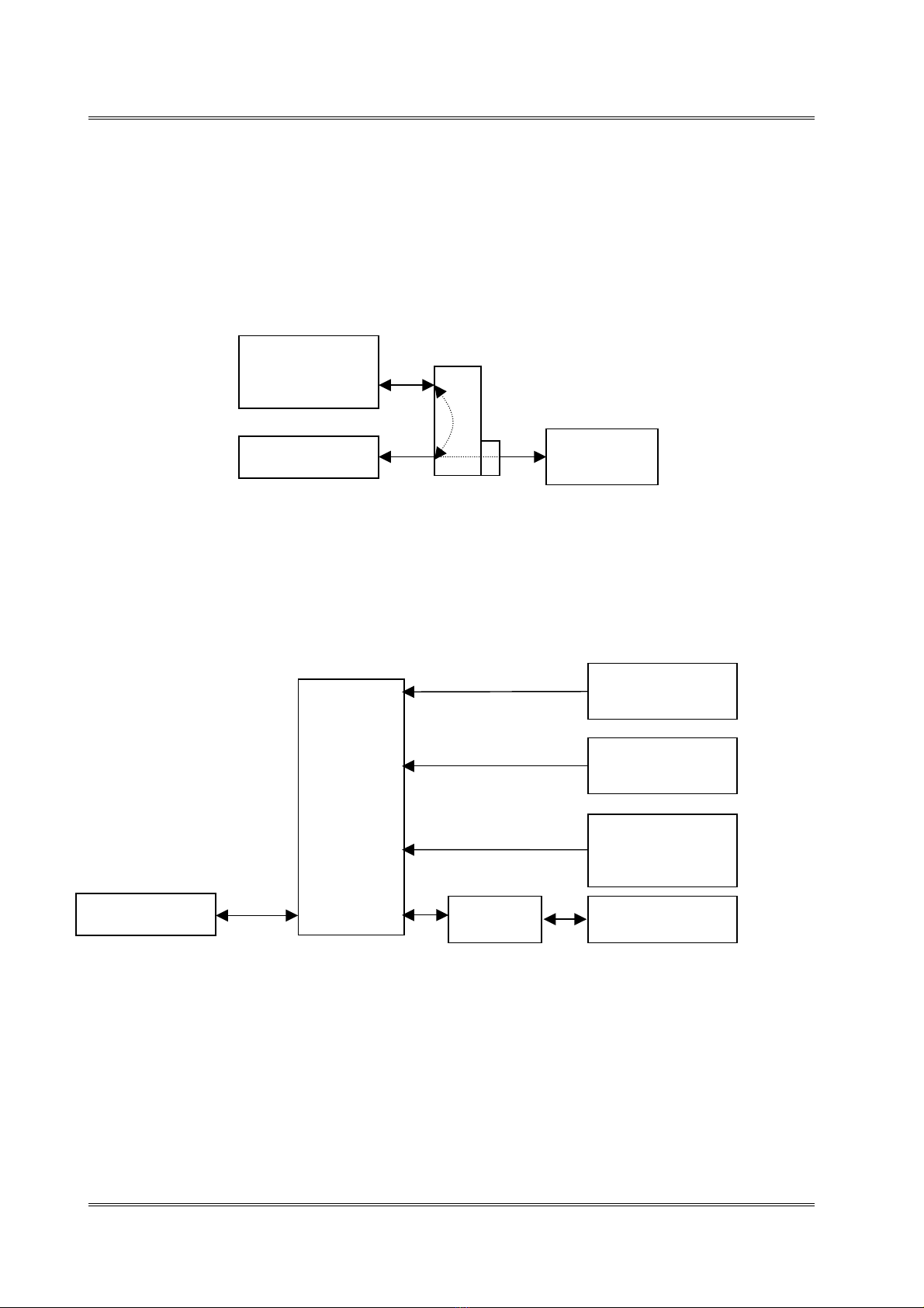
Figure 3.2.1
3.3 Conducted Monitoring and Operational Test Configuration
Figure 3.3.1
3.4 EUT Exercising Software
The EUT exercise program (if any) used during radiated and conducted testing was
designed to exercise the various system components in a manner similar to a typical use.
EUT
Spectrum
Analyzer
Companion
Device
Directional
Coupler
EUT
Multiport
Combiner
Companion
Device
Pulse Signal
Generator
SMIQ Vector
Signal Generator
3-channel
Interference
Generator
20 dB
attenuato
r

INTERTEK TESTING SERVICES
Test Report Number: HK08060834-1 Page 15 of 72
FCC ID: T7HCT8015
3.5 Details of EUT and Description of Peripherals
Details of EUT:
An AC adaptor and/or a battery (provided with the unit) were used to power the
device. Their descriptions are listed below.
(1) Base Unit: A switching AC adaptor (100-240VAC to 12VDC 300mA, Model:
SSW-1187US) (Supplied by Client)
Description of Peripherals:
(1) Telecommunication cable with RJ11C connectors (1m, unshielded), terminated
(Supplied by Intertek)
(2) CAT5 LAN unshielded cable with 2 meter long (Supplied by Intertek)
(3) A headset for telephone use with 1.2m unshielded cable. (Supplied by Intertek)
(4) Handset (Model: 420d, FCC ID: T7H-CT8010) (Supplied by Client)
(5) A 3.7V 650mAh “Li-ion” type rechargeable battery for handset (Supplied by Client)

INTERTEK TESTING SERVICES
Test Report Number: HK08060834-1 Page 16 of 72
FCC ID: T7HCT8015
3.6 Measurement Uncertainty
When determining of the test conclusion, the Measurement Uncertainty test has been
considered.
Uncertainty and Compliance - Unless the standard specifically states that measured
values are to be extended by the measurement uncertainty in determining compliance, all
compliance determinations are based on the actual measured value.
3.7 Equipment Modification
Any modifications installed previous to testing by RTX Consumer Products Hong Kong
Ltd. will be incorporated in each production model sold/leased in the United States.
No modifications were installed by Commercial & Electrical Division, Intertek Testing
Services Hong Kong Ltd.
All the items listed under section 3.0 of this report are confirmed by:
Confirmed by:
Leung Wai Leung, Tommy
Senior Manager
Intertek Testing Services Hong Kong Ltd.
Agent for RTX Consumer Products Hong Kong Ltd.
Signature
July30,2008 Date

INTERTEK TESTING SERVICES
Test Report Number: HK08060834-1 Page 17 of 72
FCC ID: T7HCT8015
EXHIBIT 4
MEASUREMENT RESULTS

INTERTEK TESTING SERVICES
Test Report Number: HK08060834-1 Page 18 of 72
FCC ID: T7HCT8015
Company: RTX Consumer Products Hong Kong Ltd. Date of Test: June 24-July 7, 2008
Model: MBU 400
4.0 Measurement Results
4.1 Antenna Requirement, FCC Rule 15.317:
EUT must meet the antenna requirement of FCC Rule 15.203.
[×] EUT uses a permanently attached antenna which is considered sufficient to
comply with the provisions of this rule. Please refer to Exhibit 5: Internal Photos
for more details.
[×] EUT uses a unique antenna jack or electrical connector which is considered
sufficient to comply with the provisions of this rule. Please refer to Exhibit 5:
Internal Photos for more details.
4.2 Digital Modulation Techniques, FCC Rule 15.319(b):
All transmissions must use only digital modulation techniques.
The requirements are made in accordance with ANSI C63.17 sub-clause 6.1.4.
Attestation:
Please refer to the technical description in section 2.2 or relevant DECT standards for
more details.
This manual suits for next models
1
Table of contents


