EnOcean EPM 300 User manual

EnOcean GmbH
Kolpingring 18a
82041 Oberhaching
Germany
Phone +49.89.67 4 689-0
Fax +49.89.67 4 689-50
www.enocean.com
Subject to modification
EPM 00(C) User Manual
October 1, 2010 10:15 AM
Page 1/11
EPM 300(C) Installation Test Tool
User Manual Template for OEM Manufacturers/First Marketer

USER MANUAL
© 2010 EnOcean | www.enocean.com EPM 00(C) OEM User Manual | Page 2/11
EPM 300 C)
REVISION HISTORY
The following major modifications and improvements have been made to the first version of this
document:
No Major Changes
1.0 Initial version
1.1 New image of antenna area
1.2 Approval chapter added
Pu lished y EnOcean Gm H, Kolpingring 18a, 82041 O erhaching, Germany
www.enocean.com, [email protected], phone +49 (89) 6734 6890
© EnOcean GmbH, All Rights Reserved
Important notes!
This information describes the type of component and shall not be considered as assured characteris-
tics. No responsibility is assumed for possible omissions or inaccuracies. Circuitry and specifications
are subject to change without notice. For the latest product specifications, refer to the EnOcean web-
site: http://www.enocean.com.
As far as patents or other rights of third parties are concerned, liability is only assumed for modules,
not for the described applications, processes and circuits.
EPM 300 and EPM 300C are designed and produced as OEM products. They will e rought
to market y local OEM manufacturers. They are not considered to e finished end products
in terms of documentation, packaging and WEEE (electronic waste regulation). EnOcean
will not e relia le for consequences of any HW or SW changes/modifications of the EPM
300(C) done y the first marketer. Product warranty and support will e covered y the
OEM.

USER MANUAL
© 2010 EnOcean | www.enocean.com EPM 00(C) OEM User Manual | Page /11
EPM 300 C)
Content
1. Introduction
2. Technical Data
3. Overview
4. Getting Started
5. Approvals
6. Recommendations
USER MANUAL
© 2010 EnOcean | www.enocean.com EPM 00(C) OEM User Manual | Page 4/11
EPM 300 C)
1. Introduction
EPM 300 C) is a mobile tool for radio link range testing. It helps electrical installers
to find the right position to mount products supporting EnOcean protocol.
EPM 300 C) is available for original equipment manufacturers OEM’s) using EnO-
cean technology within there products.
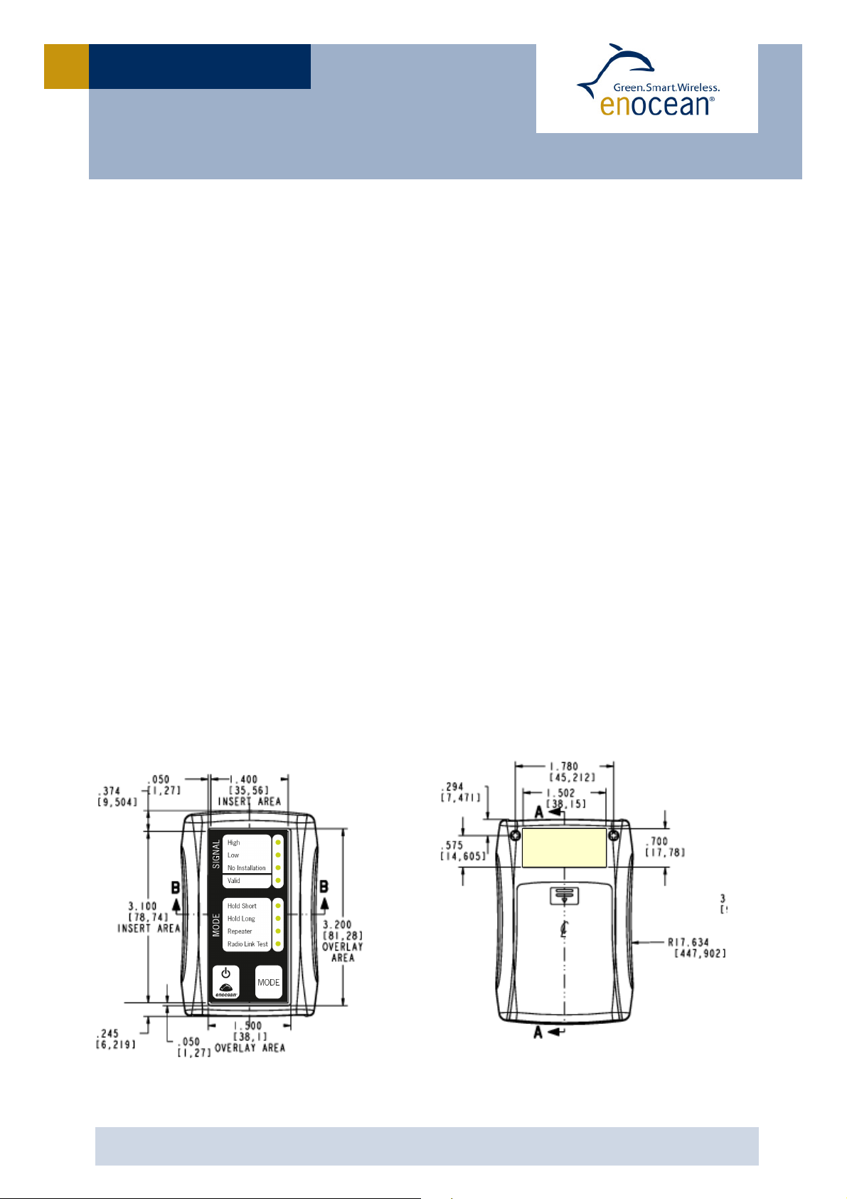
2. Technical Data
Housing size: 110 x 70 x 25 mm
OEM label size: 43 x 20 mm
Weight: 85 g w/o battery)
Battery: AA/LR06 cell
recommended Energizer L91)
Operation temperature: 0°C - +45°C
Storage temperature: -15°C - +65°C
Operation humidity: 0% - 95% r.h.
Storage humidity: 0% - 98% r.h.
Product category: IP54
R&TTE: EN 300 220 868 Mhz)
FCC / IC: CFR-47 Part15 315 Mhz)
RoHS: yes
OEM Label
Front side
Back side
USER MANUAL
© 2010 EnOcean | www.enocean.com EPM 00(C) OEM User Manual | Page 5/11
EPM 300 C)
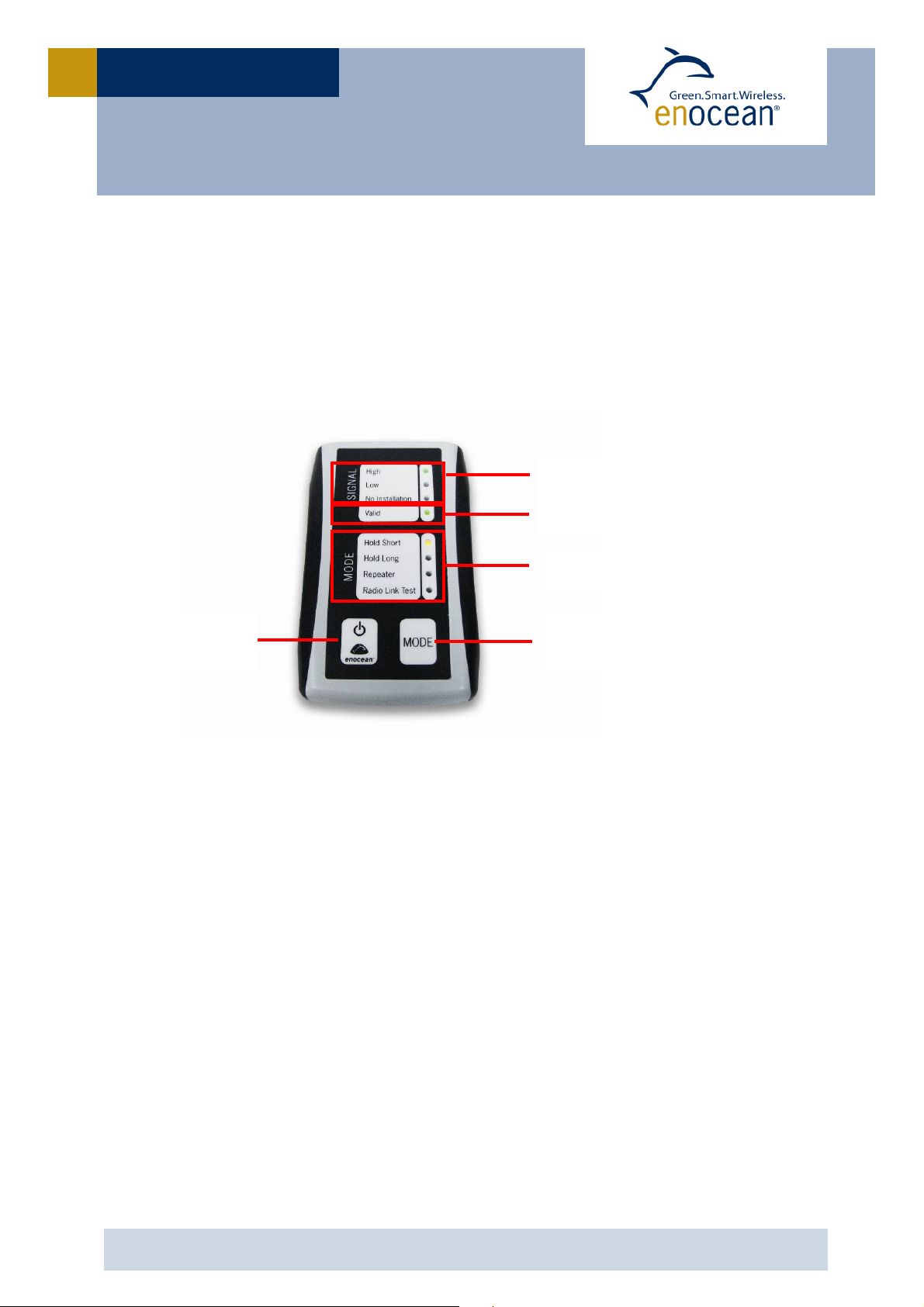
3. Overview
EPM 300 C) can be switched on and off via finger touch on the left sensor button
for more than 2 s. Operation modes will be changed via finger touch 1 s) on right
sensor button. Current mode will be indicated by four indicator LEDs. The device
can be switched off via on/off sensor button on the left side.
Radio signal intensity
On / off
utton
Valid EnOcean telegram
Mode
utton
Mode selection indicators
USER MANUAL
© 2010 EnOcean | www.enocean.com EPM 00(C) OEM User Manual | Page 6/11
EPM 300 C)
4. Getting started
1. Open battery cover backside) and insert two lithium or alkaline type
AA/LR06 batteries.
2. Activate EPM 300 C) by pressing the on/off button. Battery low will be
indicated by flashing mode LED.
3. Send EnOcean telegram by pushing a self-powered switch e.g. PTM 200)
or by pressing the learn button of a self-powered sensor.
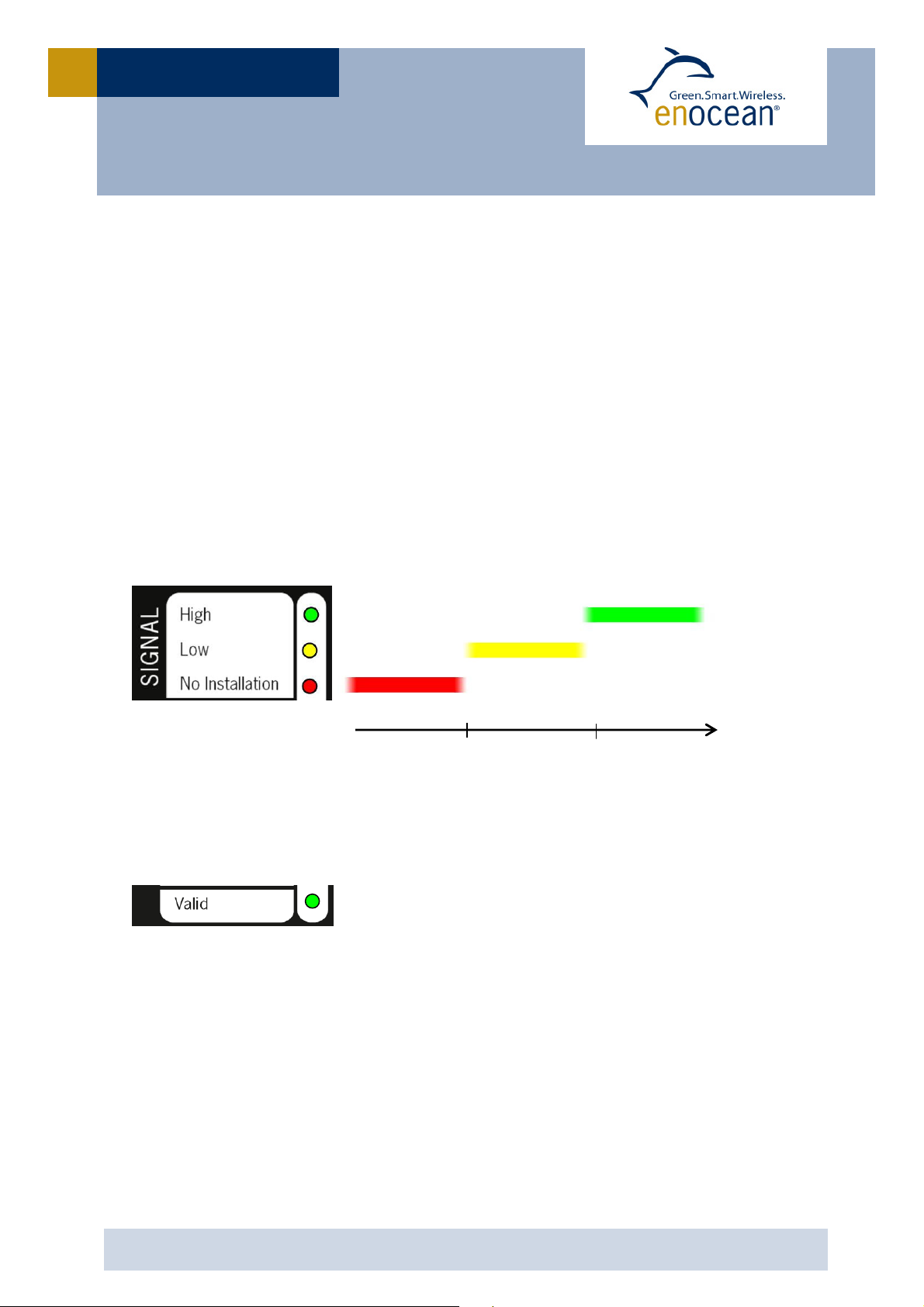
4. Signal strength RSSI value) will be shown by a reverse traffic light.
EPM 300 signal strength:
5. Valid LED shows if a valid telegram PTM switch or sensor teach-in
telegram has been received:
Valid EnOcean PTM or teach-in telegram received
internal
antenna
external
antenna

USER MANUAL
© 2010 EnOcean | www.enocean.com EPM 00(C) OEM User Manual | Page 7/11
EPM 300 C)
Signal indicators and interpretation:
Signal High & Valid indicates a very well received radio telegram. All kind
of EnOcean receivers/transceivers can be placed.
Signal Low & Valid indicates a received telegram with medium field inten-
sity RSSI) level. An external antenna or repeater is recommended.
No installation means there is no telegram received or the received tele-
gram is received at a very low RSSI level without link budget.
Signal High without Valid indicates a high level of background noise on
the same carrier frequency. This could be from other This signal will disturb
EnOcean telegrams.
Signal Low without Valid indicates a medium level of background noise on
the same carrier frequency. This “noise” can come from EnOcean sensor or
system telegrams no teach in) or
other radio devices.
EPM 300(C) has following operation modes
Peak hold short for signal strength / range test
Peak hold long for signal strength / range test
Repeater mode 1-level)
Radio link test / automatic range test

USER MANUAL
© 2010 EnOcean | www.enocean.com EPM 00(C) OEM User Manual | Page 8/11
EPM 300 C)
Detailed description with application examples:
Hold short mode will indicate every radio signal on the corresponding frequency band.
Valid telegrams will have a peak hold for 1 s. This mode is used to track radio activities
with a short period e.g. push and release telegrams of a PTM switch.
Application example:
oPerson 1 operates an EnOcean switch (e.g. PTM 200) installed at planned po
sition.
oPerson 2 monitors the received signal strength of the EnOcean telegram at
the desired mounting position of the actuator or gateway.
High & Valid > An installation at the chosen positions is recommended.
Low & Valid > An installation at the chosen positions is possible for devices with
external antenna. In case of an internal antenna the installation of
a repeater is recommended.
Hold long will indicate every signal for about 60s. This is used to test radio telegram
range by a single person installer).
Application example:
oPosition EPM 300(C) at desired actuator/receiver position.
oGo to required switch or sensor position and push the button.
oGo back to the EPM 300(C) and observe signal level held for 60s.
Attention: This mode only provides reliable information if no other switch or learn tele
grams have been sent during the time period you needed to move from the switch to
the EPM 300(C). Within the hold time no other telegram will be shown.
Repeater mode can be used to find the best position for a 1-level repeater. A 1-level
repeater will repeat a received telegram after a random delay if it is valid and original
i.e. not yet repeated). The repeated telegram will be marked as “repeated” by an in-
creased repeater counter.
Application example: Distance between switch/sensor and receiver is too long or signal
is not strong enough.
oEPM 300 #1 is placed as a repeater in between both devices.
oEPM 300 #2 monitors repeated signal at receiver position. Signal level wil be
show from the first sub telegram.

USER MANUAL
© 2010 EnOcean | www.enocean.com EPM 00(C) OEM User Manual | Page 9/11
EPM 300 C)
Radio Link Test RLT): There are two possible ways the RLT mode can be used in:
1. Basic: if the EPM 300 C) is switched to RLT, it will send telegrams periodically every
2s. Valid LED will flash for every RLT telegram sent.
Application example:
oEPM 300(C) #1 is placed at switch/sensor position and switched to mode
“Radio Link Test”.
oEPM 300(C) #2 shows field intensity of RLT signal at receiver position with
mode “hold short”.,
2. Advanced: using an advanced field tester e.g. PROBARE P30), the EPM 300 C) can
be used in slave mode. If switched to RLT, it will automatically pair with an ad-
vanced field tester AFT), where the AFT acts as RLT Master and the EPM 300 C) as
RLT slave.
Application example:
oEPM 300(C) is placed at switch/sensor position and switched to RLT mode.
oAFT is placed at receiver position, also in RLT mode.
oStart the test on the AFT it will automatically show a detailed analysis of the
connection.
For details see radio link test protocol specification at:
http://www.enocean-alliance.org/de/downloads/
Mode LED flashing indicates battery low. Please replace battery.
For performance of different batteries, refer to the following estimates:
Battery Type Continuous Measurement Stand y Time
Alkaline
e.g. Varta High Energy
AA/LR06
typ. 40 h typ. 300 days
Lithium Mignon
e.g. Energizer L91 AA/LR06
typ. 60 h typ. 500 days
Use of secondary rechargeable) batteries with 1.2 V cells e.g. Ni-Cd / NiMH) is not recom-
mended. If you don’t use your EPM 300 C) for a longer period, remove the batteries from the de-
vice. This will increase the lifetime of both batteries and the product.

USER MANUAL
© 2010 EnOcean | www.enocean.com EPM 00(C) OEM User Manual | Page 10/11
EPM 300 C)
5. Approvals
5.1 CE and R&TTE conformity (European Union)
EPM 300 868Mhz) conforms to CE and to the R&TTE EU directive on radio equipment. The
device conforms to the European and national requirements of electromagnetic compatibil-
ity. The conformity has been proven and the according documentation has been deposited
at EnOcean. The device can be operated without notification and free of charge in the area
of the European Union and in Switzerland.
Labelling according to CE and WEE has to be done by the OEM manufacturer which will
bring the product to the market.
5.2 FCC (US)
EPM 300C 315Mhz) is based on the EnOcean STM 300C radio module. This module has an
limited modular approval according to FCC. The conformity has been proven and the ac-
cording documentation has been deposited at EnOcean.
Contains FCC ID: SZV STM300C
The enclosed device complies with Part 15 of the FCC Rules. Operation is subject to
the following two conditions: (i.) this device may not cause harmful interference and
(ii.) this device must accept any interference received, including interference that
may cause undesired operation.
5.3 IC (Canada)
EPM 300C 315Mhz) is based on the EnOcean STM 300C radio module. This module has an
limited modular approval according to FCC. The conformity has been proven and the ac-
cording documentation has been deposited at EnOcean.
Contains IC: 5713A STM300C
The enclosed device complies with Part 15 of the FCC Rules. Operation is subject to
the following two conditions: (i.) this device may not cause harmful interference and
(ii.) this device must accept any interference received, including interference that
may cause undesired operation.
5.3 RoHS
EnOcean certifies that to its knowledge, EPM 300 and EPM 300C, are RoHS compliant, con-
forming to the requirements of “Directive 2002/95/EC of the European Parliament and of
the Council of 27 January 2003 on the restriction of the use of certain hazardous sub-
stances in electrical and electronic equipment.” This declaration is based on EnOcean’s cur-
rent understanding of the RoHS Directive and information provided through supplier mate-
rial declarations pertinent to the ingredients and materials comprising EnOcean products.

USER MANUAL
© 2010 EnOcean | www.enocean.com EPM 00(C) OEM User Manual | Page 11/11
EPM 300 C)
6. Recommendations
EPM 300 and EPM 300C has an internal antenna. The described area should not be covered
by metal or other shielding material. It is recommended to hold EPM 300 C) below this an-
tenna area.
Signal strength of radio signals decreases with increasing distance between transmitter and
receiver. The transmission range also depends on the materials used in the building.
The transmission range is reduced by:
increasing the distance between transmitter and receiver
shielding by metal or massive walls
mounting transmitter or receiver on the floor or close to the floor
high humidity in materials
devices generating RF interferences such as computers, audio & video equipment
or electronic gear controls for lamps. A minimum distance of 0.5 m should be kept.
For more detailed recommendations please refer to the application note “Reliable Range
Planning” at
www.enocean.com
.
Internal
antenna
This manual suits for next models
1
Table of contents


