Intewa RAINMASTER Eco User manual

WATER,WE´REINOURELEMENT
www.intewa.com
RAINMASTEREco
Installationandusermanual

1
Tableofcontents
1.Introductionandscopeofapplication................................................................................................2
1.1Modesofoperation.....................................................................................................................................3
2.Safetyinstructions..........................................................................................................................4
3.Scopeofdelivery.............................................................................................................................5
4.TechnicalData................................................................................................................................6
4.1Deviceoverviewanddimensions.................................................................................................................8
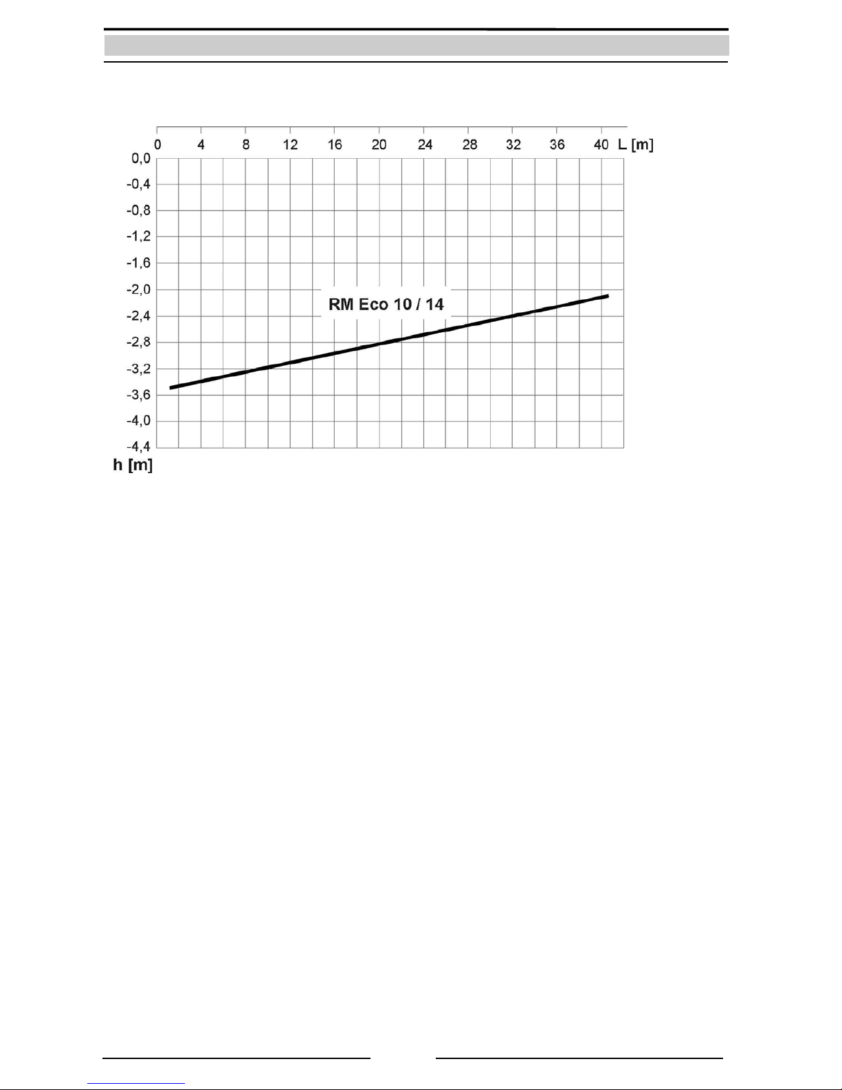
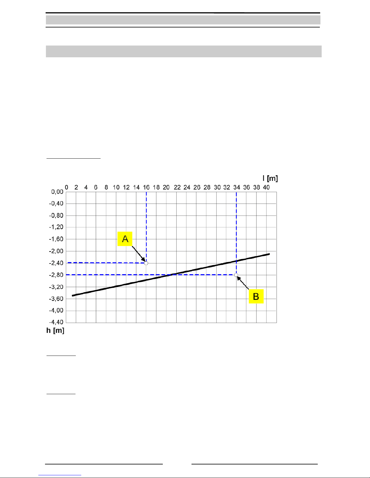
4.2.Dimensioningoftheintakeline.................................................................................................................9
4.3Standards,Directives,tests.......................................................................................................................10
5.Overviewofcomponents.................................................................................................................11
5.1Componentsofbasiccontroller..................................................................................................................11
5.2Componentsofdiaphragmpump...............................................................................................................12
5.2.1Membranpumpe.....................................................................................................................................12
5.2.2Fan................................................................................................................................................14
5.3Componentsofthesupplementalsupplycontainer.....................................................................................15
5.4Componentsofelectronic3/2‐wayballvalve..............................................................................................15
5.5Componentsofthepressurelineset...........................................................................................................16
6.InstallationinstructionsforRAINMASTEREco..................................................................................17
6.1Wallmounting...........................................................................................................................................17
6.2Connectiontothemainswaterline.............................................................................................................18
6.3Installationontheintakeside....................................................................................................................19
6.3.1Installationofaprotectiveconduitpipe.........................................................................................19
6.3.2Layoutoftheintakeline...............................................................................................................20
6.3.3Intakelineconnection...................................................................................................................21
6.3.4Installationofthefloatingintake..................................................................................................21
6.4Installationofthepressurelineset.............................................................................................................21
6.5Connectingtheemergencyoverflow...........................................................................................................23
6.6Installationandadjustmentofthefloatswitch...........................................................................................24
7.Startupanduse..............................................................................................................................25
7.1Start‐upinmainswatermode....................................................................................................................25
7.2Start‐upinrainwatermode........................................................................................................................26
7.3Modesofoperationanddisplay..................................................................................................................27
7.3.1Automaticmode(SwitchpositionI)..............................................................................................27
7.3.2Maintenancemode(SwitchpositionII).........................................................................................27
8.Troubleshootingincaseofproblems................................................................................................28
9.Maintenance..................................................................................................................................29
10.Spareparts.....................................................................................................................................30
11.Optionalaccessories.......................................................................................................................30
12.Guarantee......................................................................................................................................31
13.Contact/Devicenumber..................................................................................................................31

2
1.Introductionandscopeofapplication
CongratulationsonpurchasingyourRAINMASTEREco(RMEco).
TheRMEcoisspeciallydesignedforrainwaterandgreywaterharvestinginsinglefamilydwellings.
Optimisedforthewaterrequirementsofsmallfamilies,andusingdiaphragmpumptechnology,the
RMEcoisthefirstrainwatermoduletoofferupto70%lowerpowerconsumptionwhencomparedto
conventionalrainwatermodules.
TheRMEcoiscompatiblewiththefollowingcombinations:
Toilet/Urinal:
Youcanconnectuptothreetoiletsandoneurinal.
Note:
Themaximuminstallationheightfortoiletsandwashingmachines,
abovetheRMEcocontrolunit,is6m.Thefillingtimeoftoiletcisterns
increaseswiththesimultaneousflushingof2ormoretoilets.Ifaurinal
isusedinparalleltoothertoilets,thentheflowpressuremaynot
alwaysbesufficient.
Washingmachine:
Youcanconnectuptotwowashingmachines.
Note:
Ifmorethanonewashingmachineisconnected,oratthesametime
forexample,thegardenisbeingwatered,thendependingonthetype
ofwashingmachineused,yoursupplymaybeinterruptedifthewater
doesnotfillfastenough.Inthatcase,youmayhavetostartthe
washingmachinetime‐shifted.
Garden/Cleaning:
Forsmallwateringandcleaningtasks,agardentapcanbeconnected.
Fromthis,thefollowinggardenconsumersmaybesupplied:
‐ a20mgardenhosewithspraynozzle,or
‐ asmalllawnsprinkler‐upto2bar(29psi)/500l/hRMEco10
‐ asmalllawnsprinkler‐upto2bar(29psi)/800l/hRMEco14
‐ ahighpressurecleaner‐upto500l/hRMEco10orupto800l/h
RMEco14
Note:
‐Adripirrigationsystemneedsaspecialdimensioningin
combinationwithapressurevessel.

3
1.1Modesofoperation
Automaticmode
InAutomaticmode,thediaphragmpumpcarriesrainwaterfromthetankintothehomeandonto
respectiveapplications(e.g.toiletsetc.).Ifthetankisempty,thisisthendetectedbythefloatswitchin
thetankwhichinstructstheelectronic3/2‐waymotorisedballvalvetochangetothemainswatermode.
Thesuctionlineisthenblockedandtherequiredmainswateristakenfromthebuilt‐insupplemental
supplycontainerwithintheRMEco.Whentherainwatertankisrefilledbackwithrainwater,thefloat
switchdetectsthisandtheelectronic3/2‐waymotorisedballvalveswitchesbacktotherainwaterintake
setting.
Maintenancemode
InMaintenancemode,the3/2‐wayballvalveswitchespermanentlytomainswatermode,wherethe
consumeriscontinuouslysuppliedfromthesupplementalsupplycontainer.
Inbothmodes,thepoweronandoffofthediaphragmpumpisdonebymeansofthebuilt‐inpressure
switch.Theanti‐dryrunningprotectionofthediaphragmpump,andthestagnationprotectionofthe
supplementalwatersupply(theregularrefreshingofwaterinthesupplementalsupply)areautomatically
controlledbytheunit‘sbuilt‐inelectronics.
Optionallyfilllevelstatusindicator(RMEco‐FS)oranexternalchargingpump(RMEco‐LP)forboosting
waterintakecanbeconnectedtotheboard.
Anexampleofarainwaterharvestingsystemwithexternalstorage
1. RainwatermoduleRAINMASTEREco
2. Mainswaterconnection
3. Pressurelinesetwithexpansiontank
4. Pressurelinetoconsumers
5. Floatswitch
6. Suctionline
7. Emergencyoverflow
8. RainwaterfilterPURAIN
9. FloatingintakefilterSAUGSAGF
10. Quietinflow
11. Protectiveconduitpipeforsuctionline
andsensorcable
12. Rainwaterline
13. WallbushMD100

4
2.Safetyinstructions
Thelivecomponentshavetobeinstalledonlybyaqualifiedelectrician.Incaseof
failureoftheelectronicdevice,theproducthastoberepairedbyaqualified
electricianbeforebeingoperatedagain.Thereisariskofelectricshock!
Theoutletcircuitusedforthedevicehastobesecuredthroughacircuitbreaker
protected(16Ainseveralcountries).Ifunavailable,anFIswitchwithmaximum
operatingcurrentof30mAhastobeconnected.
Theseinstallationandoperatingguidelineshavetobereadcarefullybefore
installingtheproduct.Theinstructionsmentionedhavetobefollowedstrictly.
Modificationstotheproductarenotpermitted,otherwisethewarrantybecomes
void.
Thefollowingpointshavetobestrictlyobservedduringtheinstallationandoperation:
Checktheproductbeforeinstallationforanyvisibledefects.Ifdefectsarepresent,thenthe
productmustnotbeinstalled.Damagedproductscanbedangerous.
Installationsatthefreshwaterpipelinesystemhavetobeonlyperformedbyaqualified
installationfirm.
Afloordrainhastobeprovidedneartheinstallationsite,whichcancollectinadvertentwater
discharge(suchaswithpumpdefect,pipebreakageetc.)andpreventwaterdamageinsidethe
building.Thebrickworkbehindthewater‐carryingsystemmustbeprotectedfromwater(suchas
withwater‐resistantpaint).
Makesurethattheexistingemergencyoverflowsareconnectedandadequatelysized.
Removethemainsplugifyouwillbeawayformorethan24hours.Lockthefreshwaterlineat
theinletofthedeviceifyouwillbeawayformorethan24hours
Allproductsmustberegularlyinspectedtomaintainpropercondition.Theminimuminspection
intervalismentionedinthemaintenancemanual.
Electricdevicesmaybehazardousforchildren.Thereforechildrenalwayshavetobekeptaway
fromtheproduct.Donotletchildrenplaywiththeproduct.
Donotinstallthewater‐carryingproductsinlocationswherethetemperaturemaydropbelow0
°C.
Donotinstallanyelectricproductsinflood‐proneareas.
Theoperatorisresponsibleforadherenceofthesafetyandinstallationguidelines.

5
3.Scopeofdelivery
RAINMASTEREcomodule
wallmountingmaterialand
installationandoperatingmanual
standardaccessoryA
(mainswaterconnection):
standardaccessoryB
(pressurelineset):
standardaccessoryC
(floatswitch):

6
4.TechnicalData
RMEco10RMEco14
Dimensions(HxWxD):398x353x200mm/398x353x200mm/
Weight:8kg9kg
Switchablepowersupplyinput:110‐230VAC/50‐60Hz110‐230VAC/50‐60Hz
Switchablepowersupplyoutput:24VDC+‐5%24VDC+‐5%
Basiccontrollerinput:22‐28VDC22‐28VDC
Powerintake:90W130W
Max.operatingpressure:3,5bar/50psi3,5bar/50psi
Max.Volumeflowrate:10l/min/2.64gpm14l/min/3.7gpm
Intakeheight(self‐priming):seeintakediagramseeintakediagram
Pumpstart‐uppressure:approx.2.4bar/34psiapprox.2.4bar/34psi
Noiselevel:approx.48dbAapprox.58dbA
Permittedmainswaterpreliminarypressure:2.5‐6bar/36–87psi2.5‐6bar/36–87psi
Max.heightbetweenpumpandconsumer:10m10m
Connectormainswater(BSP):½”female½”female
Connectorpressureside(BSP):¾”female,unionnut¾”female,unionnut
Connetorintake(BSP):¾”male¾”male
Connectoremergencyoverflow
supplementalsupplycontainer: DN50/Ø55mmDN50/Ø55mm
Protectionclass: IP44 IP44
Floatswitch:
Cablelengthxcrosssection:15mxØ8mm15mxØ8mm
Protectionclass:IP68IP68
PerformancecurveofRMEco10/14

7
PerformancecurveoftheintakeofRMEco10andRMEco14

8
4.1Deviceoverviewanddimensions
1. Diaphragmpump
2.Pressureswitch
3.Linefitting
4.Switchablepowersupply
5.3/2‐waymotorisedballvalve,
intakeconnector(3/4”male)
6.Supplementalsupplycontainerwith
overflowconnectorDN50(Ø55mmmale)
7.PlaceholderforfillstatusindicatorRM
Eco‐FS(optional)
8.Basiccontroller
9.Stopcockformainswater(1/2”female)
10.Expansiontank
11.Pressureshut‐offvalve(3/4”female)
12.Ventcock
13. Fan
Topview
Bottomview

9
4.2.Dimensioningoftheintakeline
Inpractice,thepumpautomaticallystartsintakeduetodecreaseinpressure(pipefriction,intakelevel)
onlyinacertainrange.Inthisoperatingrange,itevacuatestheairfromthepumpindependentofthe
suctionline(forexample,withinitialstartupoperation).Theintakecharacteristiclineindicatesthe
dependenceofintakelengthontheintakelevel.Thedeterminedvalueisabovetherepresentedintake
lineinthediagram.Iftheintakepointisbelowtheintakeperformanceline,thenachargingpump
(optionalaccessoryRMEco‐LP)isusedtoensuretheintakeprocessproceedsreliablyandwithsufficient
safety.
Note:Thechargingpumpbooststhewaterintakepressure,sothatanintakelevelofupto3mhighcanbe
attained.Thismeansthat,theperformancecurvemoves3m(9.8ft)paralleltowardsdown.
Sampledimensions:
ExampleA:
Lengthofsuctionpipe:=16m
Intakelevel:=‐2,40m(Heightbetweendeepestsuctionpointandpump)
o.k.sinceabovethecharacteristiccurve
ExampleB:
Lengthofsuctionpipe:=34m
Intakelevel:=‐2,80m(Heightbetweendeepestsuctionpointandpump)
noto.k.sincebelowthecharacteristiccurve
RMEco‐LP(Art.‐No.220097)chargingpumpisrequired

10
4.3Standards,Directives,tests
TheRMEcomeetstheDIN1989‐4“ComponentsforControlandSupplementalSupply“standardfor
rainwaterharvestingsystems.TheDVGWmarkofapprovalconfirmsthepresenceofthemandatory“air
gap“(asperDINEN1717)forsecureseparationofprocessedwaterfromthemainswaterline,whichis
integratedintotheRMEco.
4
1
2
3
Mainswatersupplementalsupplydevice,TypeABasperDINEN1717
ThepowerissuppliedviaaTÜVGS‐certifiedswitchablepowersupply.AllcomponentsoftheRMEcoare
runon24VDClowvoltagetechnology.
TheabovementioneddevicecorrespondswiththebasicsafetyandhealthrequirementsoftheEC
directivesformachines.AnymodificationofthedevicenotcoordinatedbyINTEWAwillvoidthewarranty.
ThisequipmentspecificallyfulfillstherequirementsofthefollowingEUdirectives:
ECdirectivesformachines(89/392/EWG)inaccordancewith91/368/EWG
ECLowvoltagedirectives(73/23/EWG)
EGDirectivesforelectromagneticcompatibility(89/336/EWG)inaccordancewith93/31/EWG
TheconformityoftheequipmentwiththeabovementioneddirectivesisconfirmedbytheCEsymbol.
AppliedharmonizedEUstandards:
EN60335‐1:1194/A1/A11/A12/A13/A14,EN60335‐2‐41:1996
Appliedstandardsandtechnicalspecifications:
DIN1988‐2,DIN1989‐4,DINEN1717,DINEN13077,BGAKTW
Tests/Monitoring:
Mainswatersupplementalsupplydevice:
DIN‐DVGWmarkcertified
Mainswatersupplementalvalve:
WRASmarkcertified
Switchablepowersupply:
TÜVRheinland,TÜVGSapproved
1. Mainswaterinlet
2. Emergencyoverflow
3. Max.possiblewaterlevel
4. Airgap=secureseparationofmainswaterand
processedwater

11
5.Overviewofcomponents
TheRMEcohasamodulardesign.Eachcomponentcanbeseparatelychanged.
5.1Componentsofbasiccontroller
Filllevelsensortechnology
(seeoptionalaccessoryRMEco‐FS)
-3=+15V(brown)
-2=Signal(black)
-1=GND(grey)
Floatswitch
-2 (blue)
-1(brown)
Pressureswitch(nopolarity)
- (blue)
- (blue)
Diaphragmpump/Fan
-+24V (red)
-GND (black)
3/2‐wayballvalve
-Signal/GND(green)
-GND (black)
-
+24VDC
(red)
24VDCswitchingpowersupply
-Ø5.5Jackconnector
-optional:Connectionto24V
batterysupply
Thestagnationprotectioncanbeactivatedviaacodeswitch
onthePCB.Forthis,thefrontplatemustberemoved.
a.) Stagnationprotectionisdeactivated(Factorysetting)
ON
12
b.) Stagnationprotectionisactivated
Everytwoweeks,thesupplementalwatersupplyis
changed
ON
12

12
5.2Componentsofdiaphragmpump
5.2.1Membranpumpe
PumpforRainmasterEco10
PumpforRainmasterEco14
Thelinefittingsontheintakeandpressuresideofthepumpareprovidedwithquickreleasefasteners.The
slidelockmustbepulledoutfordismantling,thanthelinefittingcanberemoved.Whilemounting,ensure
thatthesealisassembledonlywhentheslidelockisfullyinserted!
1. Supplycable(red/black
2. Suctionconnection(unionnut/hose
3. Pressureconnection(fix)
4. Non‐return‐valve
5. O‐ringseal
6. Pressureswitchwithfastener
1. Supplycable
2. Slidelock
3. Linefitting
4. O‐ringseal
5. Pressureswitch
6. Fastenerforpressureswitch

13

14
5.2.2Fan
Thefancoolsthepumpbyauniformairflow.Ifnocontinuous
operationisprovided,thefancanbedisconnectedelectronically.
Thissavesabout6Wpower.Nevertheless,ifthepumpis
operatingcontinuously(withoutfan)withhighbackpressureand
thepumpisgettingtoohot,theinternalpumptemperature
sensorwillstopthepump.Aftercoolingdownthepumpstarts
automaticallyagain.

15
5.3Componentsofthesupplementalsupplycontainer
2 cm
3
5
4
12
Thefloatingvalvekeepsthewaterlevel
constantinthesupplementalsupplycontainer.
Themaximumwaterlevelshouldbeapprox.
2cmbelowtheoverflowrimwhenthefloating
valveisclosed(backsideofthecontainer).The
waterlevelcanbeadjustedbytwisting
theblackliftingbody.
Thefloatingvalveincorporatesaprotective
sieve.
5.4Componentsofelectronic3/2‐wayballvalve
Theballvalveselectsbetweenrainwaterintakeandmainswaterintake.Thebuilt‐indisplayshows
whichmodeiscurrentlyselected.
1. Lid
2. Emergency
overflowrim
3. Floatingvalve
4. Protectivesieve
5. Liftingbody
Positionmainswatermode
Pumptakeswaterfromthesupplementalsupply
container
Positionrainwatermode
Pumpdrawswaterfromtherainwatertank

16
5.5Componentsofthepressurelineset
Thepressurelinesetcontainsanexpansiontank,whichisnecessarytoensurethesilentoperationofthe
system.Aprimarypressureof2.0barispreloadedatmanufacture.Theexpansiontankensuresthatthe
vibrationcreatedbytheoperationofthepumpisnottransmittedthroughthepipingsystem.
Procedureforpressurecontrol/maintenanceoftheprimarypressure:
1.) DisconnectthemainspowertotheRMEco.
2.) Closethepressureshut‐offvalve.
3.) Opentheventcockfordrainingthesystempressureto0bar.
4.) Checktheairpressureintheexpansiontankwithanairpump
(withpressuregauge).Youcanuseabicyclepumporcartyre
pump.
Shouldtheprimarypressurebetoolow,useyourpumpto
increaseittothedesiredpressure.
5.) Reconnectthemainspowertostarttheunitagainanddrainthe
water,viatheventcock,untilbubblefreewatergushesout.
6.) Closetheventcockandopenthepressureshut‐offvalve.
Thesystemisnowreadytouse.

17
6.InstallationinstructionsforRAINMASTEREco
Thefoamandpolystyreneparts1‐3arepartofthetransportsafety
andmustberemovedbeforeinstallingtheRM‐Eco.
6.1Wallmounting
TheRMEcoismountedonthewallusingthemountingmaterialprovided.Thelid,bottomandlateral
distancesindicatedshouldbeadheredtowhenmountingtoprovideclearmaintenanceaccess.
275 mm
340 mm
>200 mm
>400 mm
>300 mm
Ø 8 mm Ø 8 mm
260 mm
>450 mm
TheRMEcoisfixedhorizontallywithofØ8mmrawplugsand
screws.Anadditionalholeisalsodrilled260mmtopandright
oftheuppermountingholesforconnectionoftheexpansion
tankmountingbracket.

18
Inordertoavoidvibrations,theRMEcomustbefixedwithall
fourscrews.
6.2Connectiontothemainswaterline
Theconnectiontothemainswaterlineisdonewiththeprovidedflexiblehosewithstopcock.
Note:
Theflexiblehosemustnotbemountedwithtension,sincetheinternalfloatvalveispressedagainstthe
innerwallfromhere.
Allprovidedflexiblehoseshaveglandscrewswithflatseals.Therubbersealsmustbepresent.Additional
sealingmaterialmustnotbeusedatglandnuts!
Screwtheglandscrewintothecontainerconnectionand
carefullytightenwitha30inchfixedspanner.
Screwtheglandscrewontheotherendoftheflexiblepipe
intothestopcockmountedinthemainwaterline.

19
6.3Installationontheintakeside
Theinstallationoftheintakerequiresspecialattention,sinceonlycorrectmountingandsealingensures
trouble‐freeoperationofthesystem.Forfault‐freefunctioning,ensuretheguidelinesconcerningintake
heightandintakelengtharefollowedcarefully(seeChapter4.2.).
6.3.1Installationofaprotectiveconduitpipe
Theintakelinemustbeinstalledina(e.g.DN100)protectiveconduitpipeinordertoensureallintakelines
andpipescanbeaccessedfreelyatanytime.Inordertoavoidwateraccumulatingintheconduit,itmust
beinstalledwith>1%slopebacktowardsthetank.
Ingeneral,alllinescarriedintheprotectivepipeshouldpassthroughawallbush(forexample
INTEWAMD100Articlenumber:610050),atthehouse.Throughthisbush,theintakepipeandthefloat
switchcableareroutedandsealedbyapressedrubberplate.Thispreventswaterfromoutsideentering
thebasement/garage/utilityroom.Thewallbushmustbemountedasperinstructionssothattheintake
lineisneversqueezed(contractionofcrosssection!).
1.IntakeconnectiontoRMEco
2.Intakeline
3. Wallbush
4. Protectiveconduitpipe
5.Floatingintake
Other manuals for RAINMASTER Eco
1
Table of contents
Popular Plumbing Product manuals by other brands

Grohe
Grohe 37 145 Installation

newform
newform BLINK CHIC instructions

Bristan
Bristan Blade BL BAS C Fitting Instructions & Contents List

Reece
Reece MILLI manual

Sterling Plumbing
Sterling Plumbing Shower Receptor and Wall Surround 72250100 Specification sheet

Helvex
Helvex Magna DX TV-048-S installation guide

American Standard
American Standard ARCH M968586 installation instructions

Endura
Endura 3935AX6 Installation

Bradley
Bradley Express MG-2/NDT Installation

Acorn Safety
Acorn Safety S0706 Installation, operation and maintenance instructions

Moen
Moen CHATEAU POSI-TEMP TL182BC Specifications

Lefroy Brooks
Lefroy Brooks X1-2040 Installation, operating, & maintenance instructions