Intewa AQUALOOP System GW 300 L User manual

WATER, WE’RE IN OUR ELEMENT
www.intewa.com
AQUALOOP System GW greywater recycling
AQUALOOP System GW 300 L
AQUALOOP System GW 600 L
AQUALOOP System GW 900 L
AQUALOOP System GW 1200 L
AQUALOOP System GW 1500 L
AQUALOOP System GW 1800 L
Installation and operating instructions

1
Contents
1.Introduction .........................................................................................................................................................................................2
2.Dimensioning and general description for the AQUALOOP GW series ........................................................................... 3
2.1Functional description.............................................................................................................................................................. 4
2.2Influent quality ........................................................................................................................................................................... 5
2.3Effluent quality ........................................................................................................................................................................... 6
2.4Certification NSF/ANSI 350 -2014 .......................................................................................................................................... 6
3.General safety instructions.............................................................................................................................................................. 7
4Declaration of conformity, electrical standards, approvals.................................................................................................. 8
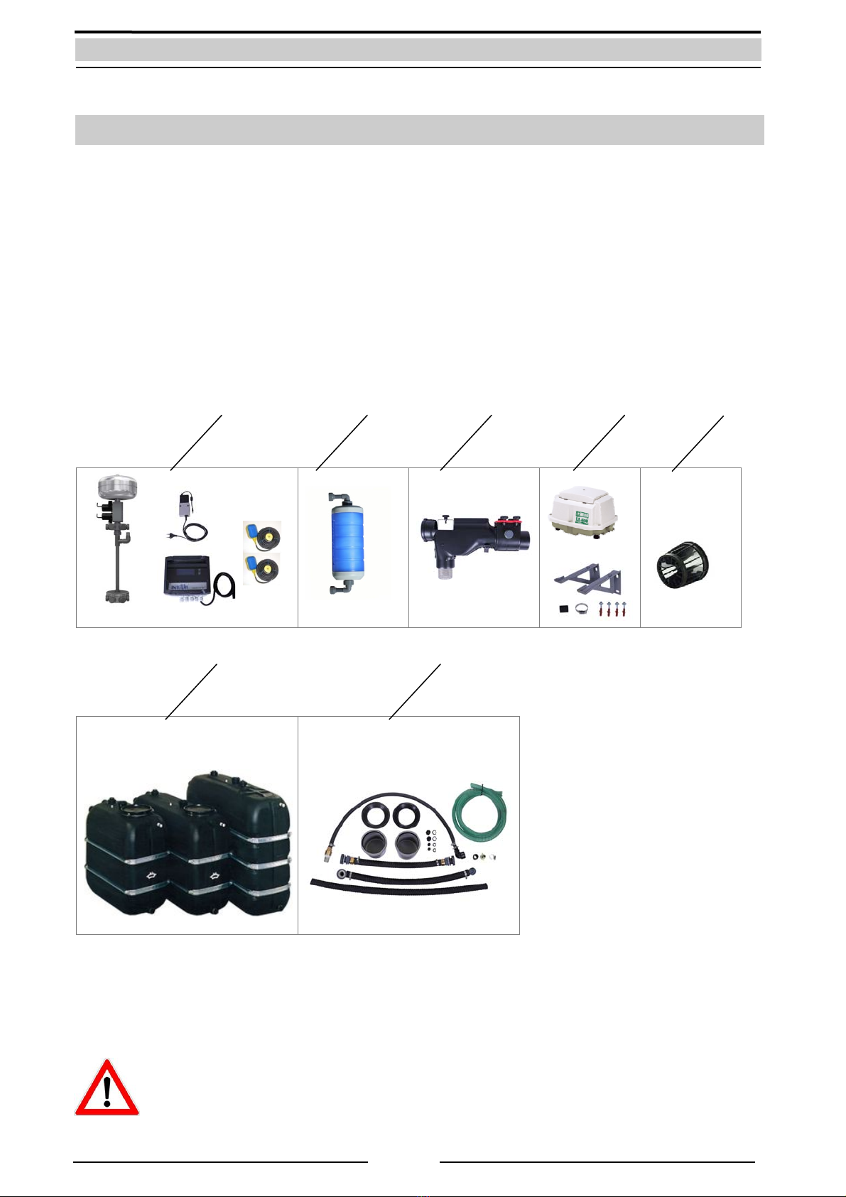
5.Scope of delivery, Transporting, Storage ...................................................................................................................................9
6.Technical data and installation details......................................................................................................................................10
6.1Membrane station control unit............................................................................................................................................ 10
6.2Membrane station...................................................................................................................................................................12
6.3Membrane cartridge............................................................................................................................................................... 14
6.4Pre-filter......................................................................................................................................................................................16
6.5Blower.........................................................................................................................................................................................17
6.6Growth bodies .......................................................................................................................................................................... 17
6.7Pressure sensor aeration........................................................................................................................................................18
6.8Sludge pump.............................................................................................................................................................................18
7.Electrical function and operation of the control unit...........................................................................................................19
7.1Electronic connections ...........................................................................................................................................................19
7.2Menu overview .........................................................................................................................................................................22
7.2.1Operating mode display.........................................................................................................................................26
7.2.2Menu settings and description ............................................................................................................................27
8Installation and connection ..........................................................................................................................................................31
8.1Data plate and labelling of the control unit ............................................................................................................................33
9.System start-up .................................................................................................................................................................................34
9.1Tightness test ............................................................................................................................................................................34
9.2Start-up phase of the bioreactor..........................................................................................................................................34
9.3Starting the bio reactor ..........................................................................................................................................................35
9.4References: Bio reactor in process........................................................................................................................................35
10.Trouble shooting ..............................................................................................................................................................................36
11.Maintenance and replacement instructions ...........................................................................................................................38
11.1Pre-filter......................................................................................................................................................................................38
11.2Suction and Back flush pump...............................................................................................................................................39
11.3Floating switch.........................................................................................................................................................................39
11.4Pressure sensor .........................................................................................................................................................................39
11.5Blower.........................................................................................................................................................................................40
11.6Membrane .................................................................................................................................................................................41
11.6.1Mechanical cleaning of the membrane.............................................................................................................41
11.6.2Chemical cleaning ....................................................................................................................................................42
11.6.2.1In-Situ cleaning in the bioreactor.................................................................................................42
11.6.2.2Intensive cleaning in an separate cleaning tank.....................................................................45
11.6.3Cleaning solution......................................................................................................................................................46
11.7Bio reactor ................................................................................................................................................................................. 47
11.7.1Collecting effluent samples...................................................................................................................................48
12.Spare parts..........................................................................................................................................................................................48
13.Optional accessory...........................................................................................................................................................................49
14.Limited Warranty / Service policy / Contact............................................................................................................................50

2
1. Introduction
In grey water recycling the contaminated water from shower, bath tub, hand basin and washing
machine is collected and processed for reuse in toilet flushing, garden watering, washing machines and
household cleaning purposes. The storage volume required for a grey water system is very small, as the
water accumulates daily, therefore grey water systems require little space.
The major benefit of grey water recycling: In many countries, customers are levied twice for municipal
water - once for the amount of mains water used and once for the amount sent down the waste pipe. By
installing an AQUALOOP grey water system and re-using your water again around the home, you save
twice as much on your municipal bills.
The AQUALOOP System is specially designed for grey water utilization in commercial applications.
Depending on the number of membrane cartridges connected, it can treat up to 1800 Litres of grey
water per day.
All AQUALOOP components make up the system and are installed by the client in a tank.
This manual describes the assembly, settings, start-up procedure and maintenance of the AQUALOOP
System including a troubleshooting guide.
Fig.: AQUALOOP System components

3
2. Dimensioning and general description for the AQUALOOP GW series
The AQUALOOP membrane station can be equipped with 1 to 6 membrane cartridges. In the standard
grey water application 300 litres per day is filtered using one single membrane cartridge. One fully
equipped membrane station (using 6 membrane cartridges) generates a daily flow of 1800 litres.
The bioreactor (treatment tank) size depends on the daily volume to be recycled and the blower size
depends on the amount of membrane cartridges utilised.
AQUALOOP System GW 0300 L 0600 L 0900 L 1200 L 1500 L 1800 L
Daily treatment
quantity (L/day) *300 600 900 1200 1500 1800
Bioreactor net volume
V
BR,use (L) ** 100-300 200-600 300-900 400-1200 500-1500 600-1800
Al-MS: Membrane station (pcs.) 1 1 1 1 1 1
Al-MEM: Membrane cartridge (pcs.) 1 2 3 4 5 6
AL-F100: Preliminary filter (pcs.) 1 1 1 1 1 1
AL-FK: Support medium (L) 30 60 90 120 150 180
AL-BLxxx: Blower size AL-BL100 AL-BL100 AL-BL120 AL-BL120 AL-BL200 AL-BL200
AL-VIP: sludge pump AL VIP AL VIP AL VIP AL VIP AL VIP AL VIP
* Typical average daily grey water yield and demand
** VBR,use = VBR, max - VBR, min ;
Tab.: System specifications for the various AQUALOOP System model sizes
4
1
23 5 76
8
9
= 1090
= 700
= 1020
= 1284
H
BR, min
L = 1320
H
Tank
H
CL, out
H
Inlet
H
Sewer
> H
Sewer
Fig.: Example of an AQUALOOP system 300L (with one equipped membrane cartridge)
1. AL-30FK, growth bodies
2. Bioreactor tank,
LxHxW=1320x1284x720mm
3. AL-F100, pre-filter
4. AL-B, Blower
5. AL-MS, Controller
6. Clear water outlet
7. AL-MS, Membrane station
8. AL-MEM, Membrane cartridge
9. AL-VIP, Sludge pump

4
2.1 Functional description
2
910
11
6
7
3
48
5
1
min.
Fig.: Installation layout of AQUALOOP System GW
The grey water (1) from bathroom (bath tub, shower, basins) and washing machine outflow is first
filtered by the pre-filter (3) and then enters the bio reactor (2). In case the bio reactor is full of water, the
grey water overflows directly into the sewer (6) via the filter overflow. The built in non-return valve
prevents the backflow of water, small animals and vermin from entering the tank. With each overflow of
the bioreactor the ground sediments are automatically extracted through the suction overflow (4) in the
AQUALOOP pre-filter. If the overflow has reached its maximum capacity, the water overflows through
the integrated skimmer and thereby cleans the floating debris (foam, grease, oil) from the surface of the
water. The sludge pump (5) is connected at a further pre-filter connection and is used for cleaning and
maintenance of the system. The sludge pumped outlet is directly routed into the sewer.
In the bio reactor the grey water is treated biologically (aeration/growth bodies). The aeration (9) is
produced by the Blower and regulated by the AQUALOOP control unit (10). The aeration pipe is
connected on the bottom side with the membrane cartridge (8). The aeration has two functions:
Aeration for the biological water treatment and for the cleaning of the membrane fibres themselves.
After the biological treatment the suction pump of the membrane station starts the microfiltration
process and the filtered, clear water is pumped to the clear water outlet. After each suction interval (15
min) the membrane is cleaned with a back flush sequence (15 sec).
The minimum level of the bio reactor is controlled by a floating level switch. The filtration process is
interrupted if the minimum is indicated. The bio reactor is ventilated via a ventilated grey water inlet
pipe (12) or a separate ventilation pipe.
1. Greywater inlet (ventilated)
2. Bioreactor
3. Pre-filter
4. Suction overflow hose
5. Sludge pump
6. Sewerage system
7. Membrane station with suction
and back flush pump
8. Membrane cartridge
9. Blower
10. Control unit
11. Permeate outlet
12. Ventilated pipe
12

5
2.2 Influent quality
The AQUALOOP System 300-1800L designed for greywater treatment.
Greywater is only recognized as water from shower, bath tub, hand basin and washing machine! Never
kitchen, dishwasher or toilet water!
Permitted use of the following detergents and cleaning products:
All usual detergents and personal cleaning products (soap, shampoo, shaving cream, toothpaste
etc.) may be used.
All household cleaning agents are safe to use in accordance with the manufactures directions for
home use.
Attention:
Please monitor the water inlet quality and ensure that substances which are not
allowed to enter the bioreactor DO NOT because the membrane filter can
become blocked or possibly destroyed.
Furthermore the outlet water quality can’t be guaranteed for safe reuse in this
case!
Water inlet qualities and substances which are not allowed:
Faeces and kitchen water, fats and chemicals (e.g. paints, thinners ) must not be fed to the
system.
Hair dyes that can cause discoloration of the process water.
Note:
Influent greywater quality shall not exceeded NSF/ANSI 350-2014 test levels (Systems treating bathing and
laundry source waters combined.)
The 30-day average concentration of the graywater delivered to the system shall be as follows:
Parameter Range
CBOD (mg/L) 130 - 180
TSS (mg/L) 80 - 160
turbidity (NTU) 2
temperatur 25 – 35 °C
E. coli (cfu/100 mL) 102 – 103
pH (SU) 6.5 – 8.0
total phosphorous – P (mL) 1.0 – 3.0
total Kjeldahl nitrogen – N (mL) 3.0 – 5.0
COD (mg/L) 250 – 400
TOC (mg/L) 50 – 100
total coliforms (cfu/100 mL) 103 – 104
Tab.: Influent quality according to NSF/ANSI 350-2014

6
2.3 Effluent quality
The required and final tested treated effluent quality according to NSF/ANSI 350-2014 listed in the table
below:
Measure Class C
requirement Class C
AQUALOOP Test result NSF approval
Measure Test
Average Single
Sample
Maximum
Result
Average Single
Sample Maximum
CBOD (mg/L) 10 25 5 17
TSS (mg/L) 10 30 2 7,8
turbidity (NTU) 2 5 0,57 3,89
E. coli 2 (MPN/100 mL) 2,2 200 1,0 13,0
pH (SU) 6.0 – 9.0 NA1 7,38 NA1
color MR3 NA MR3 NA
odor Non offensive NA Non offensive NA
oily film and foam Non-detectable Non-detectable Non-detectable Non-detectable
1 NA: not applicable.
2 Calculated as geometric mean.
3MR: measured and reported only.
2.4 Certification NSF/ANSI 350 -2014
Model designations: AQUALOOP System GW 0300 L
AQUALOOP System GW 0600 L
AQUALOOP System GW 0900 L
AQUALOOP System GW 1200 L
AQUALOOP System GW 1500 L
AQUALOOP System GW 1800 L
The model designations are tested to meet the requirements in NSF/ANSI 350 corresponding to the
designated classification:
Number and Date of NSF/ANSI Standard: NSF/ANSI 350-2014
Onsite residential and commercial water reuse
treatment Systems
Certificate No.: C0241944 - 01
Class of grey water input: Combined, bathing and laundry water effluent
Class of treated water output: Class C, multi-family and commercial facilities
Performance classification,
(nominal hydraulic daily flow)
AQUALOOP System GW 0300 L = 300 Litres / day
AQUALOOP System GW 0600 L = 600 Litres / day
AQUALOOP System GW 0900 L = 900 Litres / day
AQUALOOP System GW 1200 L = 1200 Litres / day
AQUALOOP System GW 1500 L = 1500 Litres / day
AQUALOOP System GW 1800 L = 1800 Litres / day
NSF Product and Service Listings see link below:
http://info.nsf.org/Certified/Wastewater/Listings.asp?TradeName=&Standard=350

7
3. General safety instructions
The live components have to be installed only by a qualified electrician. In
case of failure of the electronic device, the product has to be repaired by a
qualified electrician before being operated again. There is a risk of electric
shock!
The outlet circuit used for the device has to be secured through a circuit
breaker protected (16 A in several countries). If unavailable, an FI switch with
maximum operating current of 30 mA has to be connected.
When working inside of the tank or on electrical components always unplug
the power cord first.
National rules and electrical standards must be considered!
These installation and operating guidelines have to be read carefully before
installing the product. The instructions mentioned have to be followed strictly.
Modifications to the product are not permitted, otherwise the warranty
becomes void.
National rules and safety standards must be considered!
The following points have to be strictly observed during the installation and operation:
Check the product before installation for any visible defects. If defects are present, then the
product must not be installed. A damaged product can be dangerous.
A floor drain has to be provided near the installation site, which can collect inadvertent water
discharge (such as with pump defect, pipe breakage etc.) and prevent water damage inside the
building. The brickwork behind the tank installation position must be protected from water
(such as with water-resistant paint).
Make sure that the existing emergency overflows are connected and adequately sized.
All products must be regularly inspected to maintain proper condition. The minimum inspection
interval is mentioned in the maintenance chapter.
Electric devices may be hazardous for children. Therefore children always have to be kept away
from the product. Do not let children play with the product.
Do not install the water-carrying products in locations where the temperature may drop below
0 °C.
Do not install any electric products in flood-prone areas.
The operator is responsible for adherence of the safety and installation guidelines
Access ports of the tank system shall be protected against unauthorized intrusions (e.g. lockable
plant room, a padlock, locking the cover with specialized tools or cover with net weight > 30 kg).
The national and local regulations with regards to the installation and operation of a
grey water treatment system must be complied by the installer as well as the operator.

8
4 Declaration of conformity, electrical standards, approvals
The AQUALOOP electrical equipment corresponds with the basic safety and health requirements of the
EC directives for machines. Any modification of the equipment not coordinated by INTEWA will void the
warranty.
INTEWA GMBH hereby declares that the electrical equipment of AQUALOOP fulfils the requirements of
the following EU directives and conforms to the following safety standards for electrical appliances:
EC directives for machines (89/392/EWG) in accordance with 91/368/EWG
EC Low voltage directives (73/23/EWG)
EG Directives for electromagnetic compatibility (89/336/EWG) in accordance with 9
Applied harmonized EU standards:
EN 60335-1: 1194/A1/A11/A12/A13/A14, EN 60335-2-41: 1996
The conformity of the equipment with the above mentioned directives is confirmed by the CE symbol.
Approval:
Switchable power supply:
TÜV Rheinland, TÜV GS approved

9
5. Scope of delivery, Transporting, Storage
1. AQUALOOP-MS, membrane station with control unit, switching power supplier, floating switch (2pcs.)
2. AQUALOOP-MEM, membrane (numbers depending on necessary daily flow rate)
3. AQUALOOP-F100, pre-filter
4. AQUALOOP-BL , blower (size depends on the numbers of cartridges)
5. AQUALOOP-FK30l, growth media material (depends on the daily flow rate)
6. Bioreactor tank (size depends on the daily treated water amount)
7. Installation material:
Connection pipe for pre-filter Ø110mm
3 pcs. cable ducts PG 11 with nut
½“ clear water hose
1“ aerator hose, inside and outside
Data plate and service label (no shown)
Fig.: Scope of delivery and on site material
The AQUALOOP parts delivered in cartons or on pallet. All parts could unloaded manually (also the
tanks).
All parts have to be stored dry and frostproof. The tank can be stored outside but have to be protected
against direct sunlight and heat by using a bright, opaque covering.
Attention please:
The parts may be damaged by inappropriate or rough handling.
Do not throw or drop parts.
1 2 3 4 5
6 7

10
6. Technical data and installation details
6.1 Membrane station control unit
Dimensions (H x W/(incl. AC switching power
supply) x T):
201 x 198 (329) x 110 mm
Mains supply central controller (230V-IN): 110 - 230 V AC / 50-60 Hz
AC switching power supply input: 110 - 230 V AC / 50-60 Hz (24 V DC, 4.0 A)
AC switching power supply output: 24 V DC, 4.0 A
Cable length of mains supply: 3 x 1.0 mm² x 1.5 m
Cable length of AC switching power supply: 3 x 0.75 mm² x 2.0 m
Power outputs:
-Blower (230V Air): 110 - 230 V AC / 50-60 Hz, max. 4 A
-Sludge pump (230V Sludge): 110 - 230 V AC / 50-60 Hz, max. 4 A
Low voltage outputs:
-Suction pump: 24 V DC, max. 4 A
-Back flush pump: 24 V DC, max. 4 A
-Blower (Air): 24 V DC, max. 4 A (alternative )
Signal inputs:
-Bioreactor MIN (BR min): Floating switch, normally open contact
-Clear water tank MAX (CL max): Floating switch , normally open contact
-Clear water tank MIN (CL min): Pot, free contact (alternative)
Potential-free signal output:
-Clear water tank MIN (CL min OUT): Signal of CL max
Signal inputs:
-Pressure sensor Membrane hub (ADr): 4 … 20 mA
-Pressure sensor blower (ADg): 4 … 20 mA
-Programmer connection: 6 pol., RM 2.53
Protection type: IP54
Material unit case: PS, PA
Float switch:
Function: Normally open contact (MIN = closed contact)
Cable length x Diameter, Material: 15 m x Ø8 mm, 2 x 0.75mm², H07 RN-F
Protection type: IP68
Material: PP
Fig.: Dimensions of controller with DC switching power supply (Front and top view

11
Fig.: Drilled hole distances of controller housing and DC switching power supply brackets
Note: Pay attention that there is space to open the housing lid above the housing and a place for cable
routings below the housing installation space (each at least 190 mm).
Electric connections:
-All electric cables are now to be connected to the controller.
The spring terminal is opened with the supplied screwdriver.
1.) Insert slotted screwdriver in the top opening, then
press from top (arrow direction) and hold.
2.) Insert cable in the opening underneath. Then release
the screwdriver (terminal closes) and remove.
Note:
-IMPORTANT: It must be observed during connection of the
electrical wiring that the bottom pump is the suction pump
(clamp terminal: suction pump) and the top pump is the back
flushing pump (clamp terminal: back flush pump).
Fig.: Operating mode spring terminal
Finally, insert the cable bridge plug and firmly press until it is
fully inserted.
Fig.: cable bridge

12
6.2 Membrane station
Article: AL-MS
Dimension (Ø x H): max. Ø 504 x 833 mm (with max. mounting)
Weight without Membranes: 3,5 kg
Central blower connection: Nozzle, Ø 25 mm
Clear water connection: ¾“ AG
Power consumption suction- / back flush
pump
30-60 W (depending on the number of membranes
connected
Max. length / height clear water pipe: max. 10m / 2 m
Height of the clear water hose outlet HCL, outlet > HSewer
Pump cable 2 x 0.75mm² x Ø 6mm, 3 m
Protection type of pump: IP68
Material: PVC (Fittings), ABS (Pump-body), PE (Pump), ceramic
(Pump axle) SS304 (back flush tank)
Total weight (total/gross): 11.0 kg / 12.5 kg
Ø 25
879
488
380 1
8
7
6
5
4
3
2
504
3/4"
80
149541
Ø260
Fig. Dimensions of Membrane station
1. Back flush container
2. Back flush pump
3. Suction pump
4. Permeate distribution nozzle
5. Central aeration connector
6. Membrane
7. wheel weight
8. Aeration distribution
Minimum water level (BRmin = 700 mm

13
All connection points are sealed with O-rings or flat seals.
Fig.: Connectors of the membrane station
GS 1 : 1 ¼“ O-Ring
GS 2 : 1“ Flat seals
GS 3: 1 ¼“ Flat seal
GS 4: 1“ O-Ring

14
6.3 Membrane cartridge
Article: AL-MEM
Measure cartridge (Ø x H): Ø 164 mm x 410 mm
Connection size with ell-
outlets: Ø 164 mm x 486 mm
Weight: 1.6 kg
Membrane filter area: 6 m²
Membrane fibre material / -
type: PE / hollow fibre membrane
Fibre diameter / -quantity / -
length: 0.41 mm – 0.44 mm / 1600-2000 / 740 mm ± 15 mm
Pore size: 0,1 – 0,3 μm (0,2 μm nominal)
Anti-fouling: yes
Pre-wetting: yes
Flow range: 30 l - 600 l/h
Temperature range: 0 - 55 °C
Max. trans membrane pressure: 0,7 bar
Max. back-flush pressure: 2,5 bar
Max. free chlorine at 25°C or
subordinate: 5000 ppm at 9.5 pH during chemical treatment
Max. treatment pollution (free
chlorine): 1.0 Mio ppmh (hours accumulated)
Material protection cartridge
and circuit points:
PP (central permeat pipe, housing, cap, bottom), U-PVC (nut), ABS
(potting housing), NBR (O-ring), Polyol (potting resin)
Connection aeration / permeat
branch: 1 ¼“ AG / 1 ¼“ AG
O-ring-seal: Ø 26 mm x 3.5 mm, NBR
Patented: yes
Economic life-time: up to 10 years
Germ test certificate: Accredited laboratory HUS Salzburg
Testing standard: ÖNORM EN ISO 9308-1
Fig.: Dimension membrane cartridge

15
Fig.: Lower side of membrane (aeration)
Fig.: Upper side (permeate) of membrane with
interlocking ring (OPEN / LOCK)
Note:
The membrane cartridge has a blower connection (aeration)
and a permeate connection. The membrane cartridge is
always operated in a vertical position, whereby the blower
connection is situated at the bottom. (The air should rise
upwards in the cartridge through the fibre bundles.)
The lower side of membrane used with the blower
connection can be distinguished by the larger holes.
The top side of membrane with the permeate connection is
distinguished by 18 slotted slits and the external interlocking
ring. The blue cover of the cartridge is fixed with this.
Attention: Please check, that the interlocking ring is in the
LOCK position when you mount the membrane in the bio
reactor!
The membrane connections are equipped with an O-ring nut
into which an O-ring is inserted.

16
6.4 Pre-filter
Article: AL-F100
Dimensions: (L x B x H): 605 mm x 180 mm x 358 mm
Weight: 3.5 kg
Branch: DN100/ Ø 110 mm (bush)
Wastewater outlet: DN100/ Ø 110 mm (spigot end)
Max. branch: 5 l/s
Rough filter cage (Ø x H): Ø 95 mm x 120 mm
Mesh size scalping screen: 2 mm
Overflow siphon: Ø 1" (25 mm)
Sludge pump connection: 1 1/4"
Skimmer: integrated
Non-return valve: DN100, integrated
Height difference Inlet-outlet 50 mm
Material filter body: PP
Material filter mesh: stainless steel
Material non-return valve: stainless steel
1
1. Grey water
2. Sludge pump
3. Emergency overflow
4. Suction overflow connection
5. Skimmer
6. Filter basket
23
5 4
6

17
6.5 Blower
Article: AL-BL30L* AL-BL60L* AL-BL100L AL-BL120L AL-BL200L
Blower size: 30 L 60 L 100 L 120 L 200 L
Length: 207 mm 305 mm 408 mm 408 mm 418 mm
Width: 182 mm 214 mm 210 mm 210 mm 212 mm
Height: 205 mm 188 mm 232 mm 232 mm 268 mm
Power supply 230 V AC/50-60Hz
Pressure working
range up to
0,11 bar 0,15 bar 0,18 bar 0,2 bar 0,3 bar
Aeration flow 17–35 l/min 20–85 l/min 50–128 l/min 75–145 l/min 110–280 l/min
Power consumption 29 W 65 W 100 W 130 W 215 W
Hose connection hose Ø 18 mm Ø 18 mm Ø 26 mm Ø 26 mm Ø 26 mm
Proctection class IP54 IP54 IP54 IP54 IP54
Weight incl. wall braket 2,9 kg 5,0 kg 9,4 kg 9,4 kg 12,5 kg
*not usable for NSF applications
108
X
Ø 8 mm
6.6 Growth bodies
Article: AL-FK
Diameter: 36 mm
Height: 30 mm
Geometric surface: 320 m²/1 m³
Density range: 0.95 - 1.10 g/1 cm³
Material: HD-PE - Recycled
Color: black
Packaging unit: 30 l
Blower Plug distance X
AL-BL 30 110 mm
AL-BL 60 195 mm
AL-BL 100 285 mm
AL-BL 120 285 mm
AL-BL 200 240 mm
Plug drilling Ø 8 mm

18
6.7 Pressure sensor aeration
Article: AL-BPS
Measuring range: 0 to +0.6 bar
Connection: 4-20 mA,
Cable: Ø5mm, 3 m length
Material: stainless steel, PP, NBR, PVC
6.8 Sludge pump
Article: AL-VIP130/6
AL-VIP130/6 B (on request)
Operating voltage: AL-VIP130/6: 230 V AC/ 50 Hz, 4A
AL-VIP130/6 B 230 V AC/ 60 Hz, 4A (on request)
Dimension: Ø165 x 290 mm
Lifting height: max. 6 m
Lifting volume: max. 120 l/min
Pressure connection: 1 ¼ “, hose bush Ø 25mm
Cable length: 10 m
Weight: 4 kg

19
7. Electrical function and operation of the control unit
7.1 Electronic connections
1
2
14
13
13
Input
24 VDC
12111098765
12
11
9
10
230 V AC24 V DC
8
7
5
6
43
4
3
2
1
ON
1 2
NIMH 200mAh
+
-
15
17
Sig GND Ub
ADr-Pump
Sig GND
Float-Sw
BR min
PE N L
230V-AIR
PE N L
230V-SLUDGE
PE N L
230V-IN
GNDS +
Pump
Suction
GNDS +
AIR
GNDS +
Pump
Backflush
Sig GND
Float-Sw
BRmaxOUT
Sig GND
Float-Sw
BR max
Sig GND
Float-Sw
CL max
Sig GND Ub
ADg-Air
+
16
Fig.: Electrical connections of control board and assigning cable routings
(cable bridge)
This manual suits for next models
5
Table of contents
Other Intewa Water System manuals
Popular Water System manuals by other brands

Tuxhorn
Tuxhorn tubra-FRISTA KL Assembly and operating guide

Kärcher
Kärcher WPC 600 BW manual

EcoloxTech
EcoloxTech 240 Operation manual

Kärcher
Kärcher WaterClean 600 LP operating instructions

Hans Grohe
Hans Grohe Raindance Select S 120 26530000 Instructions for use/assembly instructions

CELECTIC
CELECTIC 80 L Installation and user instructions