Intewa RAINMASTER Favorit User manual

0
RAINMASTER Favorit
Installationandusermanual
WATER,WE’REINOURELEMEN
T
www.intewa.com
New Zealand Distributor: [email protected]

1
Table of contents
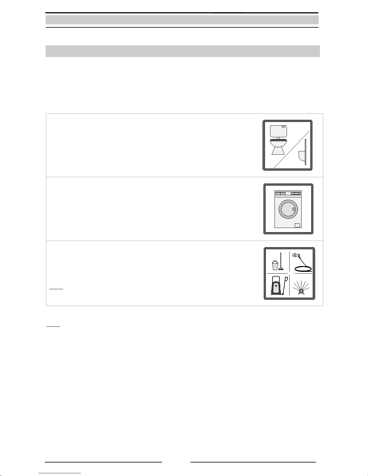
1. Introduction and scope of application ........................................................................................................................................ 2
1.1Modes of operation ................................................................................................................................................................. 3
2. Safety instructions .............................................................................................................................................................................. 4
3. Scope of delivery ................................................................................................................................................................................ 5
4. Technical Data ..................................................................................................................................................................................... 6
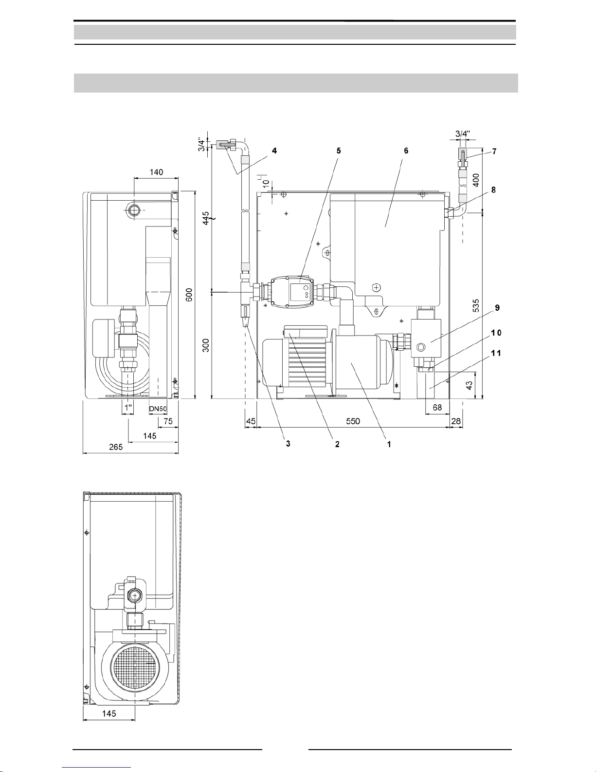
4.1Device overview and dimensions ....................................................................................................................................... 7
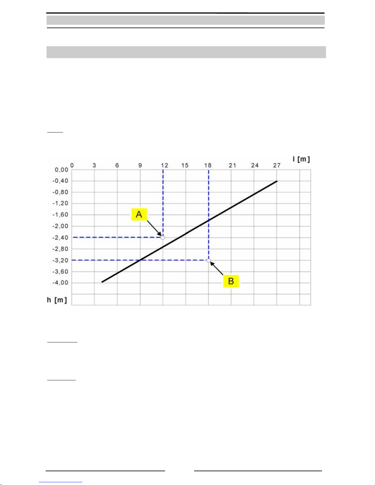
4.2.Dimensions of the intake line .............................................................................................................................................. 8
4.3Standards, Directives, tests ................................................................................................................................................... 9
5. Overview of components ............................................................................................................................................................... 10
5.1Components of the pump-controller ............................................................................................................................... 10
5.2Components of the basic controller ................................................................................................................................. 11
5.2Components of the multistage pump ............................................................................................................................. 13
5.3Components of the supplemental supply container .................................................................................................. 15
5.4Components of the electronic 3/2-way ball valve ....................................................................................................... 15
6. Installation instructions ................................................................................................................................................................... 16
6.1Wall mounting .......................................................................................................................................................................... 16
6.2Connection to the mains water line .................................................................................................................................. 17
6.3Installation on the intake side ............................................................................................................................................. 18
6.3.1Installation of a protective conduit pipe ............................................................................................................ 18
6.3.2Layout of the intake line .......................................................................................................................................... 19
6.3.3Intake line connection .............................................................................................................................................. 20
6.3.4Installation of the floating intake ......................................................................................................................... 20
6.4Installation of the pressure line set ................................................................................................................................... 21
6.5Connecting the emergency overflow .............................................................................................................................. 21
6.6Installation and adjustment of the float switch ............................................................................................................ 23
7. Start up and use ................................................................................................................................................................................. 24
7.1Start-up in mains water mode ............................................................................................................................................ 24
7.2Start-up in rainwater mode .................................................................................................................................................. 25
7.3Modes of operation and display ........................................................................................................................................ 26
7.3.1Automatic mode (Switching position I ) ............................................................................................................ 27
7.3.2Maintenance mode (Switch position II )............................................................................................................. 27
8. Trouble shooting in case of problems ........................................................................................................................................ 28
9. Maintenance ....................................................................................................................................................................................... 29
10.Spare parts ........................................................................................................................................................................................... 29
11.Optional Accessories ........................................................................................................................................................................ 29
12. Guarantee............................................................................................................................................................................................. 30
13. Contact / Unit serial number ......................................................................................................................................................... 30

2
1. Introduction and scope of application
Congratulations on purchasing your RAINMASTER Favorit (RM Favorit).
The RM Favorit is specially designed for rainwater and greywater harvesting in large single family
dwellings, multiple family dwellings and in commercial and industrial applications. The maximum
installation height for toilets, washing machines and other applications, above the RM Favorit, is 15 m.
The RM Favorit is compatible with the following combinations:
Toilet / Urinal:
You can connect several toilets and urinals.
Washing machine:
You can connect several washing machines.
Garden / Cleaning:
You can connect all types of garden hoses and sprinklers as well as cleaning
devices, in line with the maximum pump flow rate of RM Favorit 20 or
RM Favorit 40 units.
Note:
A drip irrigation system may require a special layout in combination with an
expansion vessel.
Note:
The sizing of the system, with respect to the required maximum volume flow, is governed in Germany by
regulation DIN 1988-3.

3
1.1 Modes of operation
Automatic mode
In Automatic mode, the pump carries rainwater from the tank into the home and onto respective
applications (e.g. toilets etc.). If the tank is empty, this is detected by the float switch in the tank, which
instructs the electronic 3/2-way ball valve to change to the mains water mode. The rainwater intake line is
then blocked and the required mains water is sourced from the built-in supplemental supply container
inside the RM Favorit. After it rains, and the tank is topped-up with rainwater again, the float switch
detects this and the electronic 3/2-way ball valve switches back to the rainwater intake setting.
Maintenance mode
In Maintenance mode, the electronic ball valve stays permanently switched to mains water mode, and the
house is continuously supplied with mains water from the supplemental supply container inside the
RM Favorit.
In both working modes, the pump is switched on and off by means of the built-in pressure switch. The
anti-dry running protection of the pump, and the stagnation protection of the supplemental water supply
(the regular refreshing of water in the supplemental supply) are automatically controlled by the unit‘s
built-in pump-controller.
An example of a rainwater harvesting system with external storage
1. Rainwater module RAINMASTER Favorit
2. Mains water connection
3. Pressure line set with air vent and stopcock
4. Pressure line to house
5. Float switch cable
6. Suction line
7. Emergency overflow
8. PURAIN rainwater filter
9. Floating intake filter model SAUGSAGF
10. Quiet inflow
11. Protective conduit pipe for suction line and sensor cable
12. Rainwater line into the tank
13. MD100 wall bush

4
2. Safety instructions
This installation and operating manual is to be read carefully before installing the device. The instructions
specified here are to be accurately followed, as failure to do so may lead to rejection of any warranty
claim. This also applies to modifications to the RM Favorit. Moreover, any modification of the
supplemental supply device or the electronic inside the unit will immediately nullify the warranty.
The user is responsible for compliance with safety and installation regulations. Only the original provided
packaging is to be used for transportation of the equipment.
The emergency overflow of RM Favorit must always be connected.
Installation of the mains water line must only be carried out by an authorized installation company.
The RM Favorit internal housing for live electrical components shall only be opened by a
qualified electrician.
The electrical circuit used to power this device must be protected by a 16A circuit breaker. Likewise, an
ELCB (earth-leakage circuit breaker), with a maximum operating current of 30 mA, is to be used.
The operator is responsible for the compliance with safety regulations and for following these installation
guidelines.

5
3. Scope of delivery
RAINMASTER Favorit unit
Wall mounting material and
installation and user manual
Standard accessory A
(Mains water connection):
Standard accessory B
(Pressure line set):
Standard accessory C
(Float switch):

6
4. Technical Data
RM Favorit 20 RM Favorit 40
Dimensions (H x W x D) 595 x 550 x 265 mm 595 x 550 x 265 mm
Weight: 32 kg 33 kg
Power supply input: 230 V AC / 50 Hz 230 V AC / 50 Hz
Power rating: 0,8 kW 1,25 kW
Power intake: 4 A 5,8A
Motor capacitorr: 12,5 µF 20 µF
Max. operating pressure: 4,5 bar 5,5 bar
Max. volume flow rate: 80 l/min 110 l/min
Noise level: ca. 60 dBa ca. 65 dBa
Intake height (self-priming): see intake diagram see intake diagram
Pump start-up pressure: 1,0 – 2,2 bar (adjustable),
factory setting: 1,5 bar
1,0 – 2,2 bar (adjustable),
factory setting: 1,5 bar
Protection class: IP 54 IP 54
Max. mains water pressure: 2,5 - 6 bar 2,5 - 6 bar
Highest consumer above RM Favorit: 15 m 15 m
Float switch:
Cable length x Cross section:
15 m x Ø9 mm, (3 x 1,0mm²)
Protection class: IP68 IP68
Performance curve of the pump
Performance curve of the intake

7
4.1 Device overview and dimensions
1. Multistage RM Favorit 20 / 40 centrifugal pump
2. Pump terminal box with basic controller
3. Vent cock
4. Pressure shut-off valve (3/4“ female)
5. Pump-controller
6. Supplemental supply container
7. Stopcock for mains water (3/4“ female)
8. Mains water floating valve
9. Electronic 3/2-way ball valve
10. Intake line (1“ female)
11. Emergency overflow line (DN 50/Ø55mm)
View from left
View from right Front view

8
4.2. Dimensions of the intake line
In practice, the self-priming function of the pump depends due to decrease in pressure (pipe friction,
suction level) only in a certain range. In this operating range, the pump can evacuate the air out of the
suction line (for example, with initial start-up operation). The performance curve of the intake line
indicates the dependence of intake length on the intake level. The determined value is above the
represented intake line in the diagram. If the intake point is below the intake performance line, then a
charging pump (optional accessory RMF-LP) is used to ensure the intake process proceeds reliably and
with sufficient safety.
Note: The charging pump boosts the water intake pressure, so that an intake level of up to 3 m high can
be attained. This means that, the performance curve moves 3 m parallel towards down.
Sample dimensions:
Example A:
Length of suction pipe: = 12 m
Intake level: = 2.40 m (Height difference between deepest intake level and pump)
o.k. because it’s above the performance curve
Example B:
Length of suction pipe: = 18 m
Intake level: = 3.20 m (Height difference between deepest intake level and pump)
not o.k. because it’s below the performance curve
RMF-LP (Article No: 22 00 76) charging pump is required, in order to boost intake pressure to meet
the requirements)

9
4.3 Standards, Directives, tests
The RM Favorit meets the DIN 1989-4 “Components for Control and Supplemental Supply“ standards for
rainwater harvesting systems.. The DVGW mark of approval confirms the presence of the mandatory „“air
gap“ (as per DIN EN1717) for secure separation of processed water from the mains water line, which is
integrated into the RM Favorit.
4
1
2
3
Mains water supplemental supply device, Type AB as per DIN EN 1717
The above mentioned device corresponds with the basic safety and health requirements of the
EC directives for machines. Any modification of the device not coordinated by INTEWA will void the
warranty. This equipment specifically fulfils the requirements of the following EU directives:
EC directives for machines (89/392/EWG) in accordance with 91/368/EWG
EC Low voltage directives (73/23/EWG)
EG Directives for electromagnetic compatibility (89/336/EWG) in accordance with
93/31/EWG
The conformity of the equipment with the above mentioned directives is confirmed by the CE symbol.
Applied harmonized EU standards:
EN 60335-1: 1194/A1/A11/A12/A13/A14, EN 60335-2-41: 1996
Applied standards and technical specifications:
DIN 1988-2, DIN 1989-4, DIN EN1717, DIN EN 13077, BGA KTW
Tests/Monitoring:
Mains water supplemental supply
device:
DIN-DVGW mark certified
1. Mains water inlet (floating valve)
2. Emergency overflow
3. Max. water level (in case of malfunction)
4. Air gap = secure separation of mains water and
processed water

10
5. Overview of components
The RM Favorit has a modular design. Each component can be separately changed.
5.1 Components of the pump-controller
The pump-controller (see Chapter 4.1) monitors the pressure and volume flow rate in the pressure line
system. The direction of flow is marked by an arrow on the housing.
The green LED (3) indicates ready to use. The red LED (2) indicates an error. That means the pump
controller registers air in the system and when this happens the red LED flashes. If this state continues for
more than 12 seconds, the pump undergoes an EMERGENCY STOP. The red LED then remains
continuously lit.
After an EMERGENCY STOP, the pump is restarted by pressing the RESET button (1) (or alternatively, by
disconnecting the plug from the electrical supply).
The pump-on pressure can be set using the adjustment screw (5). This adjustment is required only in
special cases. It is recommended that only experienced professionals use the pressure setting option. The
pump-on pressure is set to 1.5 bar by default. That means the pump switches on when the system
pressure falls below 1.5 bar. (Anti-clockwise rotation decreases the power-on pressure. Clockwise rotation
increases the power-on pressure.) The pump-on pressure can be controlled whereby the water pressure is
released very slowly. (The only way to know the exact pump-on pressure is by the pressure indicator,
which will indicate the slowly dropping pressure.)
Note:
The adjustment screw (5) should not exceed the limit of maximum pump pressure! If it is too high for use,
then a separate pressure limiter must be added on the pressure side. In special cases of constant pressure
use, the RM Favorit-SC is suitable. Here you can electronically set the maximum allowable pressure.
1. RESET Button
2. Light diode green: In use
3. Light diode red: Error
4. Electric connection output Pump (BR
5. Setting options power-on pressure
6. Pressure connection (1“ male) to consumer
7. Electric connection input 230 V AC
8. Pump connection (1“ male)
9. Pressure gauge

11
Wiring of the pump controller
5.2 Components of the basic controller
The unit’s basic controller (see chap. 4.1) is located in the terminal box (position [1]) and here all the
electronic components of the RM Favorit are connected, along with the motor condenser (position [2])
required for starting the motor. On the side of the terminal box is the mode selection switch I / II (position
[3]) for Automatic and Maintenance mode. (See chapter 7.3 for functional description)
Wiring of the pump terminal
Floating switch
SS (12): green/yellow
SS brn (16): brown
SS bl (17): blue
[1]
[2]
[3]

12
item Board
inscription Description of connection item Board
inscription Description of connection
1
2
3
4
5
6
7
8
9
10
11
KH PE
BR PE
NE PE
NE bl
S1 brn
S1 bl
BR brn
BR bl
BR schw
PU bl
PU brn
Protective conductor ball valve
Protective conductor pump controller
Protective conductor mains connection
N- Mains connection 230V~, blue
Selection Switch brown
Selection Switch blue
L1-Pump controller brown
N-Pump controller blue
Pump controller black
N-Pump blue
L1-Pump brown
12
13
14
15
16
17
18
19
20
21
22
SS PE
PU PE
LP PE
NE br
SS brn
SS bl
KH schw
KH grün
KH rt
LP bl
LP brn
Protective conductor floating switch
Protective conductor pump
Protective conductor charge pump
L1-Mains connection 230 V~, brown
Floating switch brown
Floating switch blue
N-Ball valve black
L1-Ball valve green
L1-Ball valve red
N-Charge pump blue
L1-Charge pump brown
Overview of the cable connections
The mode selection switch is wired with a flat pin plug.
Loosen the screws to change the condenser and take off the
cable-end eyelet ring.
Attention:
Do not let the nuts fall down into the inner coil of the motor!
Note:
When connecting a new condenser the polarity is not
important.

13
5.2 Components of the multistage pump
Expanded view of RM Favorit 20/40 centrifugal pump

14
KIT
REF.
KIT
DESCRIPTION REF.Nr. COMPONENT DESCRIPTION
38
T
IE ROD KIT ( MOTOR ~ ) 4 pcs. 4 pcs.
4 SCREW 6 pcs. 6 pcs.
5 PLUG ( FILL ~ ) 2 pcs. 2 pcs.
18 NUT ( SELF-LOCKING ~ ) 6 pcs. 6 pcs.
19 WASHER ( IMPELLER TOOTHED ~ ) 1 pcs. 1 pcs.
20 WASHER ( IMPELLER ~ ) 1 pcs. 1 pcs.
25 O-RING (PUMP BODY ~ ) 1 pcs.
79 GASKET (PUMP BODY ~ ) 1 pcs.
5 PLUG (FILL~ ) 2 pcs.
29 BEARING ( COUPLE OF ~ ) 1 pcs. 1 pcs.
36 RING ( ELASTIC ~ ) 1 pcs. 1 pcs.
25 O-RING ( PUMP BODY ~ ) 1 pcs.
24 SEAL ( COMPLETE MECHANICAL ~ ) 1 pcs.
21 IMPELLER 1 pcs. 1 pcs.
12 DIFFUSER ( WELDED ~ ) 1 pcs. 1 pcs.
33 CASE ( ~ WITH SINGLE PHASE 1 pcs. -- 1 pcs. --
45 HOLDER ( CAPACITOR ~ W/O 1 pcs. -- 1 pcs. --
439
T
ERMINAL BOX ( SINGLE PHASE ~ ) -- 1 pcs. -- 1 pcs.
44 GASKET -- 1 pcs. -- 1 pcs.
383
T
ERMINAL BLOCK 1 pcs. 1 pcs. 1 pcs. 1 pcs.
48 O-RING ( CAPACITOR BOX COVER ~ 1 pcs. -- 1 pcs. --
52 CLAMP RING 1 pcs. 1 pcs. 1 pcs. 1 pcs.
55 SCEW ( CAPACITOR COVER ~ ) 5 pcs. -- 5 pcs. --
56 GASKET ( CORDING CLAMP ~ ) 1 pcs. 1 pcs. 1 pcs. 1 pcs.
54 SCREW ( CAPACITOR HOLDER ~ ) 1 pcs. -- 1 pcs. --
74 CASE ( ~ WITH 3 PHASE STATOR -- 1 pcs. -- 1 pcs.
439
T
ERMINAL BOX ( SINGLE PHASE ~ ) -- 1 pcs. -- 1 pcs.
56 GASKET ( CORDING CLAMP ~ ) 1 pcs. 1 pcs. 1 pcs. 1 pcs.
44 GASKET 1 1 pcs. 1 pcs. 1 pcs. 1 pcs.
52 CLAMP RING 1 pc 1 pcs. -- 1 pcs. --
48 O-RING ( CAPACITOR BOX COVER ~ 1 pcs. -- 1 pcs. --
383
T
ERMINAL BLOCK 1 pcs. 1 pcs. 1 pcs. 1 pcs.
60 SCREW ( GROUND ~ ) 1 pcs. 1 pcs. 1 pcs. 1 pcs.
61 WASHER ( GROUND SCREW 1 pcs. 1 pcs. 1 pcs. 1 pcs.
62 WASHER ( GROUND SCREW PLAIN ~ 1 pcs. 1 pcs. 1 pcs. 1 pcs.
63 BAR ( GROUND ~ ) 1 pcs. 1 pcs. 1 pcs. 1 pcs.
380 STATOR KIT 47 CAPACITOR ZBR
24390
1 pcs. -- ZBR
2443
1 pcs. --
384 PUMP BODY 1 PUMP BOD
Y
1 pcs. 1 pcs.
406 LANTERN KIT 27 LANTERN 1 pcs. 1 pcs.
27 COVER ( MOTOR ~ ) 1 pcs. 1 pcs.
39 FAN ( COOLING ~ ) 1 pcs. 1 pcs.
41 COVER ( FAN ~ ) 1 pcs. 1 pcs.
453 SUPPORT 463 FLANGE 1 pcs.
81 MOTOR FOOT 1 pcs. 1 pcs.
122 PIN ( ELASTIC ~ ) 1 pcs. 1 pcs.
466 SPACER KIT 211 SPACER ( IMPELLER ~ ) 1 pcs.
16 16 O-RING ( NOZZLE ~ ) 1 pc 1 pcs.
84 84 PLUG (FRONT ~ ) 1 pc 1 pcs.
88 88 SHUTTER 1 pc 1 pcs.
490 490 RUBBER SPACER 1 pc 1 pcs.
89 89 SPRING ( SHUTTER ~ ) 1 pc 1 pcs.
370 370 SELF-PRIMING SUCTION 1 pcs.
RM F 20 RM F 40 RM F-SC 20 RM F-SC 40
200 BOLTS AND
SCREWS KIT
ZBR26800 ZBR26810
201 GASKAT KIT
ZBR26800
341 BEARING KIT ZBR26830 ZBR26840
ZBR26930
371 MECHANICAL
SEAL KIT ZBR25620
372 HYDRAULIC
KIT ZBR24170 ZBR24180
375 STATOR KIT
ZBR25640
ZBR26920
ZBR24280
ZBR28120 ZBR28130
ZBR26960 ZBR26970
444 FAN KIT
ZBR26650 ZBR26660
473 SELF-PRIMING
SUCTION
FLANGE KIT ZBR28140
ZBR22925
465 BASE KIT ZBR26900 ZBR26910
ZBR28140
List of spare parts for RM Favorit and RM Favorit-SC

15
5.3 Components of the supplemental supply container
The floating valve keeps the water level constant in
the supplemental supply container. The maximum
water level should be approx. 2 cm below the
overflow rim when the floating valveis closed
(backside of the container). The water level can be
adjusted by twisting the black lifting body (5).
The floating valve incorporates a protective sieve.
5.4 Components of the electronic 3/2-way ball valve
The motorised ball valve selects between rainwater intake and mains water intake. The built-in display
shows which mode is currently selected.
1. Supplemental supply
container
2. Floating valve
3. Protective sieve
4. Emergency overflow rim
5. Lifting body
6. Maximum water level
7. Emergency overlow
Mains water mode:
(Pumps mains water from the supplemental
supply container)
Rainwater mode:
(Pumps rain water from the rainwater tank)

16
6. Installation instructions
6.1 Wall mounting
The RM Favorit is mounted on a wall
with the supplied wall bracket. The
lid and lateral distances indicated
should be adhered to when
mounting, to provide clear
maintenance access.
The RM Favorit is fixed horizontally with Ø10 mm raw plugs
and screws.
The RM Favorit is wall mounted in such a way, that the groove
in the top back panel of the unit hangs off the affixed wall
bracket.

17
The provided rubber clamping device is to be fit on the back
side of the unit in the lower corners.
The unevenness of the wall can be balanced by various
screwing depths.
6.2 Connection to the mains water line
The connection to the mains water supply is done with the provided flexible hose and stopcock.
Screw the gland screw into the container connection and
carefully tighten with a fixed spanner.
Note:
The flexible hose must not be overtightened as this may
interfere with the internal float valve, on the opposite side of
the connection. All provided flexible hoses have gland screws
with flat washers. The rubber washers must be
present. Additional sealing material must not be used on
gland nuts!
Screw the gland screw on the other end of the flexible pipe
into the stopcock mounted on the mains water line.

18
6.3 Installation on the intake side
The installation of the intake requires special attention, since only correct mounting and sealing ensures
trouble-free operation of the system. For fault-free functioning, ensure the guidelines concerning intake
height and intake length are followed carefully (see Chapter 4.2.).
6.3.1 Installation of a protective conduit pipe
The intake line must be installed in a (DN100) protective conduit pipe in order to ensure all intake lines
and pipes are protected from damage and can be accessed freely at any time. In order to avoid water
accumulating in the conduit, it must be installed with > 1 % slope back towards the tank.
In general, all lines carried in the protective pipe should pass through a wall bush (for example
INTEWA MD100 Article number: 61 00 50), at the house. Through this bush, the intake pipe and the float
switch cable are routed and sealed by a pressed rubber plate. This prevents water from outside entering
the basement/garage/utility room. The wall bush must be mounted as per instructions so that the intake
line is never squeezed or kinked.
1. Intake connection to RAINMASTER Favorit
2. Intake line 1“
3. Wall bush
4. Protective conduit pipe (slope > 1%)
5. Floating intake SAUGSAGF

19
6.3.2 Layout of the intake line
Only an internally reinforced flexible (vacuum resistant) hose can be used for the intake line. This allows
for the use of a floating intake in the tank. The internal diameter of the intake line must be at least Ø 26
mm. The INTEWA intake hose (SDS 1“, Art.-Nr. 61 00 25) is designed for this requirement.
In order to avoid potential leaks at connection points, it is strongly recommended that the intake hose
(from the intake filter in the tank all the way to the RM Favorit unit) should be one piece – containing no
joins.
Warning instructions:
The internal diameter of the intake hose must be at least D=26 mm
in order to obtain full volume flow.
No water filter may be used in the intake line, since the gaskets are
not designed for underpressure. In result air could enters the intake
line.
PVC corrugated hoses are not suitable as rainwater suction lines.
Experience has shown that after some time these become brittle
and permeable to gas/air. The underpressure for intakes cannot be
built up later and the air enters the intake line.
No flexible hoses can be used in the intake region since these soft,
internal rubber coated hoses are constricted with underpressure.
The intake hose line must never bend, kink or be constricted in any
way.
Table of contents
Other Intewa Water System manuals
Popular Water System manuals by other brands

Everpure
Everpure Wrap ScaleStick EV9799-06 Specification sheet

NEXT pool
NEXT pool STERILOR Duo Installation & user guide

PAX
PAX PWM100 Installation & operation manual

Kenmore
Kenmore 625.385560 UltraFilter 650 owner's manual

Rinnai
Rinnai Circ-Logic Series manual

Condair
Condair RO-U Installation, operation and maintenance

Zip
Zip HydroTap G4 Series installation instructions

Clack
Clack CleanSource Owner's and operator's manual

Eljen
Eljen Mantis M5 Series Design & Installation Manual

Aqua Systems
Aqua Systems AQLP Series Installation, operation and service manual

Wilo
Wilo RAIN3 Series Installation and operating instructions

IXOM
IXOM Medora GridBee GF10000C owner's manual