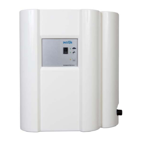
Intewa SEPAMAT F User manual

WATER,WE´REINOURELEMENT
www.intewa.com
SEPAMATF
Installationandusermanual

SEPAMATF_manual_Vers.2.8f_en1
Contents
1Introductionandscopeofapplication................................................................................................2
2Safetyinstructions...........................................................................................................................3
3Scopeofdelivery............................................................................................................................4
4TechnicalData.................................................................................................................................5
4.1Deviceoverviewanddimensions............................................................................................................6
4.2Standards,directives,tests.....................................................................................................................7
4.2.1SecureseparationCategorie5accordingEN1717...........................................................................7
4.2.2EU‐Konformitätserklärung............................................................................................................8
5Overviewofcomponents.................................................................................................................9
5.1Componentsofthepumpcontroller.......................................................................................................9
5.2Componentsofthebasiccontroller.......................................................................................................10
5.3Componentsofthemultistagepump.....................................................................................................12
5.4Componentsofthesupplycontainer.....................................................................................................13
6Installationinstructions...................................................................................................................14
6.1Wallmounting.......................................................................................................................................14
6.2Connectiontothemainswaterline........................................................................................................15
6.3Installationofthepressurelineset.........................................................................................................16
6.4Connectingtheemergencyoverflow.....................................................................................................16
7Start‐upanduse.............................................................................................................................18
7.1Start‐upinmainswatermode................................................................................................................18
7.2Display...................................................................................................................................................19
8Trouble‐shooting............................................................................................................................19
9Maintenance..................................................................................................................................20
10Spareparts.....................................................................................................................................20
11Warranty/Guarantee......................................................................................................................20
12Contact/Devicenumber..................................................................................................................21

SEPAMATF_manual_Vers.2.8f_en2
1Introductionandscopeofapplication
CongratulationsonpurchasingyourSEPAMATF.
TheINTEWAsystemseparator"SEPAMAT"isolatesthedrinkingwatersystemfromtheconsumer.It
protectsdrinkingwateragainstcontaminationcausedbybackflowofpollutantsfromtheconsumerpoint
ofuse.Systemseparationisinstalledbetweenthemunicipaldrinkingwatersupplyandoneormore
fixtures.ThesemustbeseparatedinaccordancewithCategory5ofthecurrentdrinkingwaterregulations
containedinDINEN1717.
Thehighestconsumerconnectionpointcanbeamaximumof20mabovetheSMTF.

SEPAMATF_manual_Vers.2.8f_en3
2Safetyinstructions
Thelivecomponentshavetobeinstalledonlybyaqualifiedelectrician.Incaseof
failureoftheelectronicdevice,theproducthastoberepairedbyaqualified
electricianbeforebeingoperatedagain.Thereisariskofelectricshock!
Theoutletcircuitusedforthedevicehastobesecuredthroughacircuitbreaker
protected(16Ainseveralcountries).Ifunavailable,anFIswitchwithmaximum
operatingcurrentof30mAhastobeconnected.
Theseinstallationandoperatingguidelineshavetobereadcarefullybefore
installingtheproduct.Theinstructionsmentionedhavetobefollowedstrictly.
Modificationstotheproductarenotpermitted,otherwisethewarrantybecomes
void.
Thefollowingpointshavetobestrictlyobservedduringtheinstallationandoperation:
Checktheproductbeforeinstallationforanyvisibledefects.Ifdefectsarepresent,thenthe
productmustnotbeinstalled.Damagedproductscanbedangerous.
Installationsatthemainswaterpipelinesystemhavetobeonlyperformedbyaqualified
installationcompany.
Afloordrainhastobeprovidedneartheinstallationsite,whichcancollectinadvertentwater
discharges(i.e.pumpdefects,pipebreakages,etc.)andpreventwaterdamageinsidethebuilding.
Themasonworkbehindthewater‐handlingunitmustbeprotectedfromwaterdamage(i.e.with
water‐resistantcoating).
Makesurethattheexistingemergencyoverflowsareconnectedandadequatelysized.
Removethemainselectricalplugifyouwillbeawayformorethan24hours.
Closethemainswaterlineattheinletofthedeviceifyouwillbeawayformorethan24hours.
Allproductsmustberegularlyinspectedtomaintainpropercondition.Theminimuminspection
intervalismentionedinthemaintenancesection.
Electricaldevicesmaybehazardousforchildren.Thereforechildrenalwayshavetobekeptaway
fromtheproduct.Donotletchildrenplaywiththeproduct.
Donotinstallthewater‐handlingunitsinlocationswherethetemperaturemaydropbelow0°C.
Donotinstallanyelectricalproductsinflood‐proneareas.
Theoperatorisresponsibleforadherenceofthesafetyandinstallationguidelines.

SEPAMATF_manual_Vers.2.8f_en4
3Scopeofdelivery
Separationunit
SEPAMATF
Wallmountingmaterial,
installationandusermanual
StandardaccessoryA
(Mainswaterconnection)
StandardaccessoryB
(Pressurelineset)

SEPAMATF_manual_Vers.2.8f_en5
4TechnicalData
SEPAMATF20SEPAMATF40
Dimensions(HxWxD):595x550x265mm595x550x265mm
Weight:32kg33kg
Nominalvoltage/frequency:230VAC/50Hz230VAC/50Hz
Ratedpower:0.8kW1.25kW
Ratedcurrent:4A5.8A
Motorcapacitor:12.5µF20µF
Max.dischargepressure:4.5bar 5.5bar
Max.flowrate:80l/min110l/min
Noiselevel:ca.60dBAca.65dBA
Pumpstart‐uppressure:1.0–2.2bar(adjustable),
factorysetting:1.5bar
1.0–2.2bar(adjustable),
factorysetting:1.5bar
Protectionclass:IP54IP54
Max.mainswaterpressure:2.5‐6bar2.5‐6bar
Max.highestconnectedfixture: 20m20m
PerformancecurvesforSEPAMATF20/40
SEPAMATF20
SEPAMATF40

SEPAMATF_manual_Vers.2.8f_en6
4.1Deviceoverviewanddimensions
1.MultistagecentrifugalpumpSEPAMATF20/40
2.Pumpterminalboxwithbasiccontroller
3.Ventcock
4.Pressurelineshut‐offvalve(3/4“female)
5.Pumpcontroller
6.Supplycontainer
7.Stopcockformainswater(3/4“female)
8.Mainswaterfloatingvalve
9.Emergencyoverflow(DN50)
Leftsideview
Rightsideview Frontview

SEPAMATF_manual_Vers.2.8f_en7
4.2Standards,directives,tests
4.2.1SecureseparationCategorie5accordingEN1717
TheSEPAMATFmeetstheDIN1989‐4“ComponentsforControlandSupplementalSupply“standard.The
DVGWmarkofapprovalconfirmsthepresenceofthemandatory“airgap“(asperDINEN1717)forsecure
separationofprocessedwaterfromthemainswaterline,whichisintegratedintotheSEPAMATF.
4
1
2
3
Mainswaterseparationdevice,TypeABasperDINEN1717
Certificationseparationdevice
accordingtoEN1717andDINEN1717
Safetycategory5
Certificationfloatingvalve:
1. Mainswaterinlettosupplycontainer
2. Emergencyoverflowopening
3. Max.possiblewaterlevel(incaseofmalfunction)
4. Airgapbetweeninletandmax.possiblewaterlevel
=secureseparationofmainswaterandusage
water

SEPAMATF_manual_Vers.2.8f_en8
4.2.2EU‐Konformitätserklärung
DieseEU‐KonformitätserklärungwurdeinalleinigerVerantwortungvonINTEWAGMBH
ausgestellt.
ThisdeclarationofconformityisissuedunderthesoleresponsibilityofINTEWAGmbH.
Dokument‐Nr.: 03/10/2021
Document‐No.:
Hersteller: INTEWAGmbHAnschrift:AufderHüls182
Manufacturer: Address:D–52068Aachen
Produktbezeichnung: PumpenstationTypenbezeichnung: RM‐Fxx,SMT‐Fxx
Productdesignation:pumpstationType:
DerobenbeschriebeneGegenstandderErklärungerfülltdieeinschlägigen
HarmonisierungsrechtsvorschriftenderUnion:
TheobjectofthedeclarationdescribedaboveisinconformitywiththerelevantUnionharmonization
legislation:
2006/42/EU:Maschinenrichtlinie
2006/42/EU: DirectiveMachinery
2014/30/EU: EMVRichtlinie
2014/30/EU: Directiverelatingtoelectromagneticcompatibility
2011/65/EU: RoHS‐RichtlinieII
2011/65/EU: RoHsDirectiveII
2015/863/EU RoHS‐RichtlinieIII
AngewandteharmonisierteEuropäischeNorm:
AppliedharmonisedEuropeanStandard:
EN60335‐1:2012/A11:2014:2014/A13:2010/A15:2011,ENISO12100:2010
EN61000‐6‐3:2007/A1:2011,EN61000‐6‐1:2007,EN61000‐6‐4:2007/A1:2011
EN61000‐6‐2:2005,EN55014‐1:2006/A2:2011
EN50581:2012
WeiterenormativeDokumente
Othernormativedocuments
EN60335‐2‐41:2003/A2:2010
Ort,Datum:Aachen,12.10.2021
Place,Date:
RechtsverbindlicheUnterschrift:
Legalsignature:_________________________________
GeschäftsführerOliverRingelstein
Manager

SEPAMATF_manual_Vers.2.8f_en9
5Overviewofcomponents
TheSEPAMATFhasamodulardesign.Eachcomponentcanbeseparatelychanged.
5.1Componentsofthepumpcontroller
Thepumpcontroller(seesection4.1)monitorsthepressureandvolumeflowrateinthepressureline
system.Thedirectionofflowismarkedbyanarrowonthehousing.
ThegreenLED(3)indicatesreadyforuse.TheredLED(2)indicatesamalfunction.Thismeansthepump
controllerregistersairinthesystemandifthisoccurs,theredLEDflashes.Ifthisstatecontinuesformore
than12seconds,thepumpundergoesanEMERGENCYSTOP.TheredLEDthenremainscontinuouslylit.
AfteranEMERGENCYSTOP,thepumpisrestartedbypressingtheRESETbutton(1)(oralternatively,by
disconnectingtheplugfromtheelectricalsupply).
Thepumpstart‐uppressurecanbesetusingtheadjustmentscrew(5).Thisadjustmentisrequiredonlyin
specialcases.Itisrecommendedthatonlyexperiencedprofessionalsusethepressuresettingoption.The
pumpstart‐uppressureissetto1.5barbydefault.Thatmeansthepumpswitchesonwhenthesystem
pressurefallsbelow1.5bar.(Anti‐clockwiserotationdecreasesthestart‐uppressure.Clockwiserotation
increasesthestart‐uppressure.)Thepumpstart‐uppressurecanbecontrolledbydrainingthewater
pressureveryslowly.(Theonlywaytoknowtheexactpumpstart‐uppressureisthroughthepressure
indicator,whichwillindicatetheslowlydroppingpressure.)
Note:
Theadjustmentscrew(5)shouldnotexceedthelimitofmaximumpumppressure!Ifitistoohighforuse,
thenaseparatepressurelimitermustbeaddedonthepressureside.Inspecialcasesofconstantpressure
use,theSEPAMATF‐SCissuitable.Hereyoucanelectronicallysetthemaximumallowablepressure.
1. RESETButton
2. LED,red:Malfunction
3. LED,green:Inuse
4. Pumpelectricaloutput(BR)
5. Adjustablestart‐uppressure
6. Pressureconnection(1“male)toconsumer
7. Electricalinput,230VAC
8. Pumpconnection(1“male)
9. Pressuregaugeinbar/psi(1bar=14.5psi)

SEPAMATF_manual_Vers.2.8f_en10
~
P
N
L
L1
Wiringofthepumpcontroller
(yearofmanufactureuntilbis04.2021).
~
P
NL
L1
Wiringofthepumpcontroller
(yearofmanufacturefrom04.2021).
5.2Componentsofthebasiccontroller
Thebasiccontrollerwillbefoundintheterminalboxofthepump[1],wherealltheelectricalcomponentsof
theSEPAMATFareconnected,aswellasthemotorcapacitorrequiredforstart‐up[2].
BRbl(8)
BRbrn(7)
BRPE(2)
BRschw(9)
BRbrn(7)
BRbl(8)
BRPE(2)
BRschw(9)

SEPAMATF_manual_Vers.2.8f_en11
Wiringofthepumpterminal
Pos.BoardcodeConnectiondescription
Pos
..BoardcodeConnectiondescription
1
2
3
4
5
6
7
8
9
10
11
KHPE
BRPE
NEPE
NEbl
S1brn
S1bl
BRbrn
BRbl
BRschw
PUbl
PUbrn
‐free‐
Protectivepumpcontroller
Protectivemainsconnection
N‐Mainsconnection230V,blue
‐free‐
‐free‐
L1‐Pumpcontroller,brown
N‐Pumpcontroller,blue
Pumpcontroller,black
N‐Pump,blue
L1‐Pump,brown
12
13
14
15
16
17
18
19
20
21
22
SSPE
PUPE
LPPE
NEbr
SSbrn
SSbl
KHschw
KHgrün
KHrt
LPbl
LPbrn
‐free‐
Protectivepumpcontroller
‐free‐
L1‐Mainsconnection230V,brown
‐free‐
‐free‐
‐free‐
‐free‐
‐free‐
‐free‐
‐free‐
Table:Overviewofcableconnections
Loosenthescrewstochangethecapacitorandtakeoffthecable‐
endeyeletring.
Attention:
Donotletthenutsfalldownintotheinnercoilofthemotor!
Note:
Whenconnectinganewcapacitorthepolarityisnotimportant.
[1]
[2]

SEPAMATF_manual_Vers.2.8f_en12
5.3Componentsofthemultistagepump
ExplodedviewofSEPAMATF20/40centrifugalpump
KIT
REF.
Nr. KIT
DESCRIPTION
REF.
Nr. COMPONENT DESCRIPTION
25 O-RING ( PUMP BODY ~ ) 1
24 SEAL ( COMPLETE 1
21 IMPELLER 1 pcs. 1
12 DIFFUSER ( WELDED ~ ) 1 pcs. 1
380 CAPACITOR 47 CAPACITOR ZBR 1 -- ZBR 1 pcs. --
16 16 O-RING ( NOZZLE ~ ) 1 pc 1
84 84 PLUG (FRONT ~ ) 1 pc 1
88 88 SHUTTER 1 pc 1
490 490 RUBBER SPACER 1 pc 1
89 89 SPRING ( SHUTTER ~ ) 1 pc 1
370 370 SELF-PRIMING SUCTION 1
RMF-20-A
RMF-20
SMT-F20-A
SMT-F20
RMF-20-SC
SMT-F20-SC
RMF-40
RMF-40-A
SMT-F40
SMT-F40-A
RMF-40-SC
SMT-F40-SC
371 MECHANICAL
SEAL KIT ZBR25620
372 HYDRAULIC
KIT ZBR45880 ZBR45890
473 SELF-PRIMING
SUCTION
FLANGE KIT ZBR28140
ListofsparepartsforSEPAMATF(SMTF20/F40)

SEPAMATF_manual_Vers.2.8f_en13
5.4Componentsofthesupplycontainer
Thefloatingvalvekeepsthewaterlevelconstantinthesupplementalsupplycontainer.Themaximum
waterlevelshouldbeapprox.2‐3cmbelowtheoverflowrimwhenthefloatingvalvesclosed(backsideof
thecontainer).
Thecorrectdistanceofthefloat(5)tothehorizontalleverisfactorysetat85mmbytheSMT20float
valveand90mmbytheSMT40floatvalve.
Note:Ifanoverflowoccursduetocontinuousdrippingfromthevalve,thevalvemustbedecalcified(see
Maintenance).Intheconnectionofthefloatvalvethereisaprotectivesieve(3)whichcanbepulledoutfor
cleaning.Astrainerisalsolocatedintheinletpipe.
1.Supplementalsupplycontainer 5.Liftingbody
2.Floatingvalve6.Maximumwaterleve
3. Protectivesieve7.Splashprotection
4.Emergencyoverflowrim 8.Emergencyoverlow

SEPAMATF_manual_Vers.2.8f_en14
6Installationinstructions
6.1Wallmounting
TheSEPAMATFismountedonawallwiththesupplied
wallbracket.Thelidandlateraldistancesindicatedshould
beadheredtowhenmounting,toprovideclear
maintenanceaccess.
TheSEPAMATFiswallmountedinsuchaway,thatthegroove
inthetopbackpaneloftheunithangsofftheaffixedwall
bracket.

SEPAMATF_manual_Vers.2.8f_en15
Theprovidedrubberclampingdeviceistobefitontheback
sideoftheunitinthelowercorners.
Theunevennessofthewallcanbebalancedbyvarious
screwingdepths.
6.2Connectiontothemainswaterline
Theconnectiontothemainswatersupplyisdonewiththeprovidedflexiblehoseandstopcock.
Screwtheglandscrewintothecontainerconnectionand
carefullytightenwithafixedwench.
Note:
Theflexiblehosemustnotbeovertightenedasthismay
interferewiththeinternalfloatvalve,ontheoppositeside
oftheconnection.Allprovidedflexiblehoseshavegland
screwswithflatwashers. Therubberwashersmustbe
present.Additionalsealingmaterialmustnotbeusedon
glandnuts!
Screwtheglandscrewontheotherendoftheflexiblepipe
intothestopcockmountedonthemainswaterline.

SEPAMATF_manual_Vers.2.8f_en16
6.3Installationofthepressurelineset
Thepressurelineset(seesection3)establishestheconnectionbetweenthepumpandpressureline
system.
Thepressurelinesetisconnectedtothepumpcontroller.
Theflexiblehoseandtheshut‐offvalvethenconnecttothe
pressurelinesetandthepressureline.
6.4Connectingtheemergencyoverflow
TheSEPAMATFhasanemergencyoverflowline(DN50)which
mustbeconnectedtothewastedrainagesystemofthe
building.Thedrainagelinemustbeofasizetoaccommodatea
maximumvolumeflowrateof90l/min.

SEPAMATF_manual_Vers.2.8f_en17
Note:
Thepositionofthebackwaterlevelmustbetakeninto
considerationwhileconnectingtoadrainagesystem,inorderto
preventbackflowofdrainagewaterfromtheopensewerline
(designaccordingtotheDINEN1717)enteringtheSEPAMATF.
Thepositionofthebackwaterleveldeterminesthetypeofline:
a)Backwaterlevelabovetheemergencyoverflowdrainage
heightofthesupplementalsupplycontainer:
Connectionoftheemergencyoverflowmustbedoneby
aliftingsystem.
b)Backwaterlevelbelowtheemergencyoverflowdrainage
heightofthesupplementalsupplycontainer:
Connectionoftheemergencyoverflowtoaventilated
channelline(DN50)isdoneviaasiphon.
a.)
b.)

SEPAMATF_manual_Vers.2.8f_en18
7Start‐upanduse
7.1Start‐upinmainswatermode
1.Openthemainswaterlinestopcocksothatthesupply
containerisfilledwithwater.
Note:
Inmaintenancemodethepumpprimedwithwater
automaticallyoverthemainswatertank.Inthiscasethe
pumpcannotbemanuallyfilledwithwater!
2.Closethepressurelineshut‐offvalve.
3.Opentheairvent(holdabucketofwaterundertheairvent)
andstartthepumpbyplugginginthemainspower.
Letthewaterrunfromtheairventintothewaterbucket
untilthereisnomoresignofbubbles(aclearstream)
meaningthatallairhasbeenremovedfromthesuctionline.

SEPAMATF_manual_Vers.2.8f_en19
4.Closetheairvent.
5.Openthepressurelineshut‐offvalveandflushtheairfrom
theconsumerline(e.g.byflushingthetoiletseveraltimesor
openingthegardentap).
6.Closeallthefixtures.
Thepumpwillnowautomaticallyswitchoffwhenthe
maximumsystempressureisreached.
7.2Display
ThegreenLEDonthepumpcontrollerindicatesthatthepumpisreadytouse.Incaseofaproblem,the
redLEDwilllightup(seesection5.1).
Thesystempressurecanbereadonthepressuregaugeofthepumpcontroller.
TheAutomaticModeorMaintenanceModecanbesetviathemodeselectingswitch.
8Trouble‐shooting
MalfunctionCauseSolution
Pumpdoesnotstartandthe
redLEDison
‐ Pumpshutsoffafterabrief
humandtheRESET
‐ Replacethecapacitor
‐ Nowaterintheprimingtank‐ Testthemainswatervalve
Pumpswitchesonandoff
continuously
‐ Unsealed,leakyfixture‐ Repairleak
‐ Minimalflowratethroughthe
fixture(<1l/min)
‐ Testthefixtures(forseveral
small,connectedfixtures,an
expansionvesselissuggested
toreduceswitchon‐switchoff
rate)
This manual suits for next models
2
Table of contents
Other Intewa Water System manuals
Popular Water System manuals by other brands

Kasco
Kasco CERTISAFE RM-100 Assembly & installation manual

LINDR
LINDR SODA PYGMY Instructions for use

Mikrofill
Mikrofill Extreme Series Technical documentation

STIEBEL ELTRON
STIEBEL ELTRON SBB 400 S Operating and installation instruction

EINHELL
EINHELL Royal HWA 2800 operating instructions

WaterLogic
WaterLogic WL900 Service guide

Hellenbrand
Hellenbrand PM6.O-IC-2.0 Series brochure

Sterling
Sterling SGM-250A product manual

Hog Technologies
Hog Technologies Stripe Hog SK3000 Operation manual

Vetus
Vetus 1320 installation manual

HYDROLAB
HYDROLAB R Series user manual

Xylem
Xylem Bell & Gossett NRF-25 Installation, operation and maintenance manual