Intrepid Control Systems neoOBD2-SIM User manual

neoOBD2-SIM User’s Guide
6© 2019 Intrepid Control Systems, Inc.Version 1.0 - March 11, 2019

neoOBD2-SIM User’s Guide
i © 2019 Intrepid Control Systems, Inc.Version 1.0 - March 11, 2019
Version History
Version
Number Date Description / Major Changes
1.0 2019/03/11 Initial release.

neoOBD2-SIM User’s Guide
ii
Table of Contents
1 Introduction and Overview ..........................................................................................................................1
1.1 Introduction ................................................................................................................................................1
1.2 Package Contents......................................................................................................................................1
1.3 Operational Overview ................................................................................................................................2
1.4 Summary of Key Features .........................................................................................................................4
1.5 Hardware and Software Requirements...................................................................................................... 5
2 Building Coremini Scripts Using Vehicle Spy...........................................................................................6
2.1 Basic Vehicle Spy Help ..............................................................................................................................6
2.2 Basic Commands.......................................................................................................................................6
2.3 LEDs........................................................................................................................................................10
2.4 Sending the Script for Coremini Mode.....................................................................................................10
3 Troubleshooting..........................................................................................................................................12
3.1 Possible Problems and Solutions ............................................................................................................12
4 Support Contact Information ..................................................................................................................13
4.1 ICS United States Headquarters..............................................................................................................13
4.2 ICSInternationalOfces ..........................................................................................................................13
© 2019 Intrepid Control Systems, Inc.Version 1.0 - March 11, 2019

neoOBD2-SIM User’s Guide
1© 2019 Intrepid Control Systems, Inc.Version 1.0 - March 11, 2019
1. Introduction and Overview
1.1 Introduction
The neoOBD2-SIM uses Vehicle Spy Professional or Enterprise software to create custom
simulations that make the neoOBD2-SIM act like an ECU, an OBD port, a vehicle, or an industrial
device. This is accomplished using a simple scripting interface called Function Blocks.
1.2 Package Contents
The neoOBD2-SIM package includes both hardware and software:
Hardware
The package contains the following:
● neoOBD2-SIM -- Intrepid Control Systems portable ECU simulator
● NEOVI-PS -- neoVI / neoECU Power Supply - 12V
● USB3-USBC-CABLE -- USB Type C Cable
● Quick Start Card to help you get going quickly with your device
Software
The neoOBD2-SIM package also contains a software/driver CD containing:
● A copy of Intrepid Control Systems’ Vehicle Spy vehicle network software
● AnAPIinstallkitcontainingtheneoVIExplorerutilityforconguringthedevice
If you did not purchase Vehicle Spy, a free trial version of the program will be provided instead,
which allows access to Vehicle Spy’s minimum features.

neoOBD2-SIM User’s Guide
2© 2019 Intrepid Control Systems, Inc.Version 1.0 - March 11, 2019
Figure 1: neoOBD2-SIM Package Contents
If anything is missing or damaged, please contact Intrepid Control Systems for assistance. The
contact for your locale can be found at https://www.intrepidcs.com/worldwide.
1.3 Operational Overview
The device can be powered using the built-in 2000 mAh Lithium Ion battery, the 12V power
supply, or the USB Type-C cable. The battery is charged when the power supply or USB
cable are connected and the power switch is turned on. The power switch must be turned on
to charge the battery.
Connecting to the Device
To connect to the device, take the USB cable, connect it to a PC, and open Vehicle Spy. Vehicle
Spy can be installed from the CD that was provided with the device. If no CD is available, or
a digital copy is needed, please contact Intrepid Control Systems for a replacement.
You may want to review the software install before the connection. If there isn’t software, no
driver for the device will be available.
Once the device is connected, navigate to Setup > Hardware to open neoVI Explorer. The
device information should auto populate. Highlight the neoOBD2-SIM and press Connect.

neoOBD2-SIM User’s Guide
3© 2019 Intrepid Control Systems, Inc.Version 1.0 - March 11, 2019
Figure 2: neoVI Explorer
Device settings such as Baud Rates and enabled networks can be modied. The device
rmwarecanalsobereashedherebypressingManualReash.
Whenmodicationsarecomplete,pressWriteSettingstowritethechangestothedevice.
Please note that changing settings on the device will not clear any scripts present on the
device.
Important Note:
Whenupdatingthedevicermware,DONOTUNPLUGTHE
DEVICE.Unpluggingthedeviceduringarmwareupdate
will result in irreparable damage to the neoOBD2-SIM. If the
neoOBD2-SIM is damaged, the device must be returned to
Intrepid Control Systems for repairs.

neoOBD2-SIM User’s Guide
4© 2019 Intrepid Control Systems, Inc.Version 1.0 - March 11, 2019
1.4 Summary of Key Features
The neoOBD2-SIM includes two CAN / CAN FD channels and is designed for complex script-
based simulations for interactive protocols such as ISO 14229, CCP/XCP, J1939, and more.
Construction, Controls, and Cabling
1. USBType-Cportforconguringandcharging
2. Customizable 12x4 character OLED display. This is also the location of the power switch
(left side)
3. Barrel jack for external power. Center positive, 7.5-36v DC power supply connection
4. Four programmable 360 Degree Encoder with buttons
5. Four programmable multi-color LEDs
6. Built in DIP switches to change the termination
7. Clear plastic case
8. J1962 female connector that can be connected directly to off-the-shelf scan tools
9. Built in 2000mAH Lithium-Ion battery
10.CoreMini scripting engine to run standalone scripts
11. Firmwarethatcanbeupgradedintheeld
12.Two CAN / CAN FD channels

neoOBD2-SIM User’s Guide
5© 2019 Intrepid Control Systems, Inc.Version 1.0 - March 11, 2019
Figure 3: Device Features and Locations
1.5 Hardware and Software Requirements
Hardware:
The neoOBD2-SIM is programmed through Intrepid Control Systems’ Vehicle Spy 3 software.
All commands are executed on the device using the CoreMini scripting engine. CoreMini scripts
are written using Function Blocks inside of Vehicle Spy.
Software:
A licensed copy of Vehicle Spy will be necessary to design and upload CoreMini scripts to the
device.However,thelicensedoesnotneedtobeforthespecicneoOBD2-SIM.Aversionof
software licensed for one of our other devices can be used, as long as the license is still in
maintenance.
All software can be downloaded from the Intrepid Control Systems web site.
Important note: The neoOBD2-SIM cannot be used in PC mode as an
interface. The device operates using CoreMini (Standalone) mode only.

neoOBD2-SIM User’s Guide
6© 2019 Intrepid Control Systems, Inc.Version 1.0 - March 11, 2019
2. Building Coremini Scripts Using Vehicle Spy
2.1 Basic Vehicle Spy Help
Basic use and knowledge of Vehicle Spy will be required to program this device. It is highly
recommended to attend both a Vehicle Spy Basics class and Scripting class, which is
complimentary when a Vehicle Spy license is purchased, and if the customer visits our local
ofce.F1onyourkeyboardcanbepressedforadditionalhelp.
The full Vehicle Spy Help Documentation is available here:
https://cdn.intrepidcs.net/support/VehicleSpy/vehiclespyhelpdoc.html
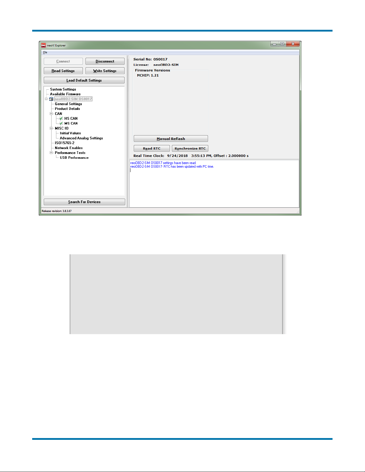
Once the device is , the next step is to build a script that tells the device what to do.
To begin, open Vehicle Spy from the shortcut on the desktop or Start menu. The software will
start with a new setup on the logon screen. Using the menu at the top, navigate to Scripting and
Automation > Function Blocks. From function blocks, press the + in the upper left-hand corner to
add a new Script type block.
A complete list of all Function Block Script commands is available here:
https://cdn.intrepidcs.net/support/VehicleSpy/spyFBScriptType.htm
2.2 Basic Commands
For now, the focus is going to be on the more commonly used commands. Additionally, there will
be more info regarding options and commands that are unique to the neoOBD2-SIM.
Set Value
Set Value is used to update variables and signals inside of Vehicle Spy. Its use is extremely
common. In addition to being able to write values to variables,there are also mathematical
functions that can be used.These mathematical functions are simple addition/subtraction, logs,
mod, rnd(1), and much more.
Function Block Action
They control other function blocks’ running status. The command can be used to start, stop, or
call other function blocks.
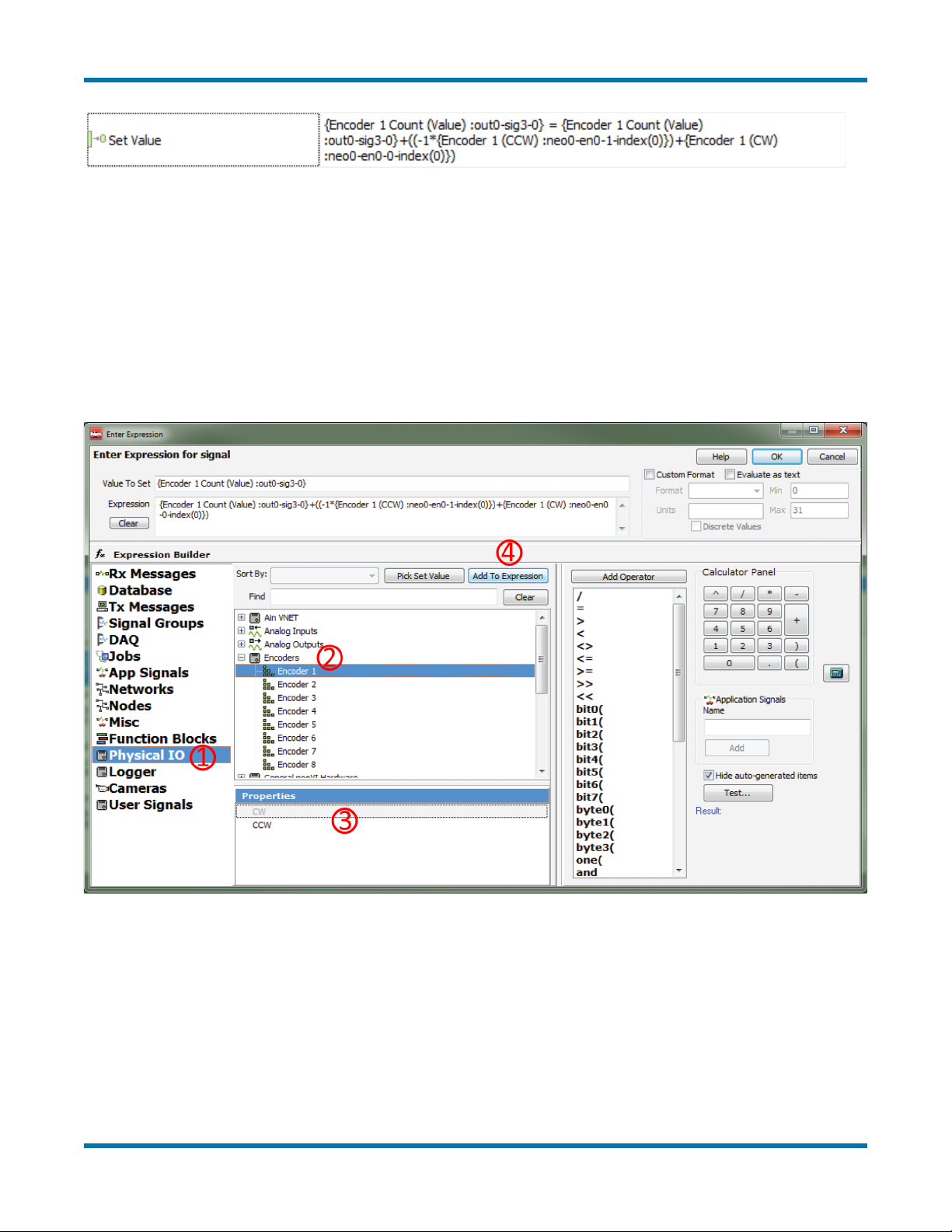
Encoders
Encoders work by using what are called ‘ticks’ in each direction to increment or decrement a
value.To calculate the current position, add any clockwise ticks and subtract any counterclockwise
ticks from a counter holding the total number of ticks. One way to do this would be implementing
an equation like this: TotalTicks = TotalTicks + (-1*CCW) + CW. This would be implemented in
the software and can be seen in Figure 4.

neoOBD2 SIM User’s Guide
7 © 2019 Intrepid Control Systems, Inc.Version 1.0 - March 11, 2019
Figure 4: Set Value Command
In this example, the variable ‘Encoder 1 Count’ is set to the old value, then added or subtracted
to depending on which way the encoder was turned. Additional steps could be added to force
limits to the values. For example, using an If statement: If X > 100, then Set value to 100. This
would limit the max value on Encoder 1 to effectively be 100.
Encoders must be added under the Physical IO section of Set Value’s Expression Editor. Please
seethegurebelow:
Figure 5: Physical IO
After double clicking the Value cell next to a Set Value command, this screen shown in Figure 5
should appear. To access the Encoders, simply go to Physical IO, then Encoders. Next, select
the direction (CW / CCW), then press Add to Expression. This will add the code to the Expression
section. Value To Set will contain the App signal or Tx Message Signal that’s being set

neoOBD2-SIM User’s Guide
8© 2019 Intrepid Control Systems, Inc.Version 1.0 - March 11, 2019
Wait Until
The Wait Until step simply pauses the function until the requested criteria is met. An example is
shown in Figure 6.
Buttons
Buttons on the neoOBD2-SIM are used by pressing the Rotary Encoders. The encoders have
a noticeable tactile click when the button is pressed.
Switches 1 through 4 will work with the neoOBD2-SIM. The example in Figure 6 below also
waits for the value to reset to 0 before restarting (this prevents the script from running more
often than intended).
Figure 6: Wait Until Step
LCD Display
The neoOBD2-SIM also has a LCD display that can also be used to display text. The LCD
display consists of four lines with twelve characters each.
When a line is full, but more characters are in the command, the remaining characters will be
truncated. When supplying text, make sure to pad out the rest of the characters to twelve with
spaces. This is because the LCD will persist characters until they are overwritten by something
else.
Log Data
Log Data will be the command used to send the text to the LCD screen.The Log Type must be
set to neoECU LCD, and the recommended starting positions (abbreviated as SP) are as follows:
Line 1: Set SP to 0
Line 2: Set SP to 12
Line 3: Set SP to 24
Line 4: Set SP to 36

neoOBD2-SIM User’s Guide
9© 2019 Intrepid Control Systems, Inc.Version 1.0 - March 11, 2019
Figure 7: Log Data Setup
Pressing the F(x) button opens the Expression Editor. ASCII characters are supported. If the
Evaluate as Text box is checked, Message and Application signals can be inserted in-line.
See below:
Figure 8: Log Data Expression Showing App Signal
With the example in Figure 8, the neoOBD2-SIM will show “Param2: 0” on the LCD screen.
Transmit
This is the command used to send a message onto the bus.
The Transmit command is used in conjunction with a Transmit message that is set up using the
Messages Editor. Examples of this can be found at the hyperlink listed on page 6. An example
of a function block using the Transmit command is shown in Figure 9. Transmit messages can
alsohavesignalsattachedtothem.Thesesignalscanalsobe modied using theSetValue
command.

neoOBD2-SIM User’s Guide
10 © 2019 Intrepid Control Systems, Inc.Version 1.0 - March 11, 2019
Figure 9: Transmit Command
2.3 LEDs
The neoOBD2-SIM also has four multicolored LEDs that are programmable using the Set Value
command. By default, the LEDs run in an automatic mode that shows different colors under
certaincircumstances,suchaswhenthedeviceisinbootloadermodewhilereashingrmware.
TousetheLEDs,therststepistoturntheAutofunctionoff.SimplysettheAutopropertyof
each LED to 0. LEDs are found under Physical IO, just like Encoders and Buttons.
Below is a snippet from a neoOBD2-SIM Example Function Block that changes LED colors
based on the encoder position values (although the values can be fed by any variables, or a static
value). The color properties have a range of 0-255, with 0 being off and 255 being maximum.
Figure 10: LED Example
2.4 Sending the Script for Coremini Mode
Once a script is ready, it’s time to send the script to the device. From Vehicle Spy click on Tools
>CoreMiniconsole.Theconsoleshouldlooksimilartothefollowinggure:

neoOBD2-SIM User’s Guide
11 © 2019 Intrepid Control Systems, Inc.Version 1.0 - March 11, 2019
Figure 11: CoreMini Console
Any errors with the script will be noted in the build tab of the CoreMini console with red LEDs.
YellowLEDsnotewarningsthatmayaffectfunctionality.GreenLEDsmeanalliswell.Once
ready, press Send to load the script onto the neoOBD2-SIM.

neoOBD2-SIM User’s Guide
12 © 2019 Intrepid Control Systems, Inc.Version 1.0 - March 11, 2019
3. Troubleshooting
3.1 Possible Problems and Solutions
Occasionally, a script can be built that may not function correctly with the device. Refer to the
listbelowforpotentialissuesandcommonxes:
Problem: The script was pushed to the device, but does not seem to be running in Standalone
mode
Solution: Make sure that the USB cable is unplugged from the neoOBD2-SIM when the
device is ready to be used. If the USB is plugged in when the device is booted, the CoreMini
script will not run. This is by design to prevent the device from loading any actively installed
scripts.
Problem: Device LCD shows the Intrepid Control Systems logo, which blinks off and back on
again. The device may seem unresponsive.
Solution: This is what’s referred to as a ‘boot loop.’ This means that a command somewhere
intheleiscausingthedevicetoreset.
If the device is stuck in a boot loop, hold down the 1 and 4 buttons (the top two). Alternately,
plug in USB. Powering up the device with these buttons pressed will purge the currently
installed script. After the script is purged, the device should act normally again. Note, plugging
in the USB only stops the script for that session; it does not purge the script. Boot loops need
tobexedinthefunctionblockcode.Thismayrequiredebugmodicationsandextensive
troubleshooting.
If the device is still acting up after a script purge, hold down all 4 buttons and repower the
device. This will send the device into bootloader, where it can be recovered by connecting to
the device using neoVI Explorer.

neoOBD2-SIM User’s Guide
13 © 2019 Intrepid Control Systems, Inc.Version 1.0 - March 11, 2019
4. Support Contact Information
If you have a problem you cannot resolve on your own, feel free to contact ICS for assistance at
oneofourofces.
4.1 ICS United States Headquarters
Our primary support personnel can be reached at our American headquarters in the Detroit area,
using the following contact information:
Phone: (800) 859-6265 or (586) 731-7950, extension 1.
Fax: (586) 731-2274.
Email: [email protected]
Intrepid’s normal support hours are from 8 am to 5 pm, Monday to Friday, United States Eastern
time. If you require assistance outside standard business hours, feel free to contact us and a
member of our support team will get back to you as soon as possible.
4.2 ICS International Ofces
UK Ofce
OurUKofcecanbereachedasfollows:
Phone: +44 24 7718 0296.
Email: [email protected]
European Union Ofce
ForsupportintheEU,pleasecontactIntrepid’sGermanyofce:
Phone: +49 721 6633703 -4.
Fax: +49 721 6633703 -9.
Email: [email protected]

neoOBD2-SIM User’s Guide
14 © 2019 Intrepid Control Systems, Inc.Version 1.0 - March 11, 2019
Japan Ofce
Intrepid’sofceinYokohamacanbereachedasfollows:
Phone: +81-(0)45- 263-9294.
Mobile Phone: 080-8884-0111.
Fax: 045-263-9296.
Email: [email protected]
Korea Ofce
In Korea, use the following contact information:
Phone: +82 31 698 3460.
Fax: +82 31 698 3461.
Email: [email protected]
China Ofce
Intrepid’sShanghaiofcecanalsobereachedbyphone,faxoremail:
Phone: +86 4006151011.
Fax: +86 021-51330271-601.
Email: [email protected]
We can also be contacted in Shenzhen:
Phone: +86 0755-82723212.
Email: [email protected]
India Ofce
In India, please use this contact information:
Phone: +91 +97 66 44 55 33.
Email: [email protected]

neoOBD2-SIM User’s Guide
15 © 2019 Intrepid Control Systems, Inc.Version 1.0 - March 11, 2019
Australia Ofce
OurAustralianofcecanbereachedasfollows:
Phone: 03 9466 4948 (international callers: +61 3 9466 4948).
Email: [email protected]
Table of contents
Other Intrepid Control Systems Automobile Accessories manuals
Popular Automobile Accessories manuals by other brands

Champion Power Equipment
Champion Power Equipment 50028 Owner's Manual and Operating Instructions

Tellur
Tellur TLL151171 user manual

POOL-LINE
POOL-LINE 110016 Assembly instructions

Yakima
Yakima GetOut instructions

Trailboss
Trailboss QTMA662L Fitting instructions

Angel Armor
Angel Armor Avail installation guide