Intrepid Control Systems RAD-Star User manual

Intrepid Control Systems, Inc.
31601 Research Park Drive Madison Heights, MI 48071 USA
(ph) +1-586-731-7950 (fax) +1-586-731-2274
www.intrepidcs.com www.aeta-rice.com
RAD-Star
BroadR-Reach® (100BASE-T1) / Ethernet Active Tap
User’s Guide
Version 1.2 - June 1, 2016

RAD-Star User’s Guide
i© 2015-2016 Intrepid Control Systems, Inc.Version 1.2 - June 1, 2016
Version History
Version
Number Date Description / Major Changes
1.0 2015/07/24 Initial release.
1.1 2016/01/20
Added version history page.
Added boot time specications.
Added mention of the formal IEEE name of BroadR-Reach (100BASE-T1).
Corrected error in description of Figure 15.
1.2 2016/06/01
Corrected length of RAD-Star frame wrapper mentioned in Section 11.
Claried requirement to use Gigabit Ethernet for conventional Ethernet switch
in high speed applications.
Added note that undersized frames are not captured by the RAD-Star.
Added contact information for ICS international oces.
General review and minor corrections/edits.

RAD-Star User’s Guide
ii © 2015-2016 Intrepid Control Systems, Inc.Version 1.2 - June 1, 2016
Table of Contents
1 Introduction ...................................................................................................................................................1
2 Package Contents........................................................................................................................................1
3 Overview of Operation and Features ........................................................................................................1
4 Description of RAD-Star Interfaces and Indicators .................................................................................4
5 Hardware and Software Requirements.....................................................................................................6
6 Cables and Connectors...............................................................................................................................8
7 Hardware Setup - Active Tap ......................................................................................................................9
8 Hardware Setup - Media Converter.........................................................................................................13
9 Troubleshooting..........................................................................................................................................16
10 Support ........................................................................................................................................................19
11 Reference: Frame Wrapping and Wrapper Format...............................................................................20

RAD-Star User’s Guide
1© 2015-2016 Intrepid Control Systems, Inc.Version 1.2 - June 1, 2016
1 Introduction
Thank you for purchasing a RAD-Star BroadR-Reach (100BASE-T1) active tap from Intrepid
Control Systems. The RAD-Star is an inexpensive but powerful tool that facilitates the design,
development, analysis and troubleshooting of Automotive Ethernet (AE) networks.
The RAD-Star is primarily used as an active tap inserted between a pair of AE devices. The
RAD-Star’s hardware passes all trafc between these devices with virtually no added latency,
while sending a timestamped copy of each message to a standard Ethernet device (such as
a laptop PC) for monitoring. The RAD-Star can also be used as a media converter, allowing
an ECU to be interfaced directly to a PC or other conventional Ethernet device. In both
applications, it is also possible to send messages from the PC to the ECU(s) using a tool like
Intrepid’s Vehicle Spy software, allowing those devices to be directly controlled.
2 Package Contents
Your RAD-Star package includes the following:
• The RAD-Star device.
• A pair of standard 4-wire Ethernet cables.
• A pair of BroadR-Reach cables terminated with Molex Mini50 connectors.
If anything is missing, please contact Intrepid for prompt assistance, using the information at
the end of this guide. More information about cabling can be found in Section 6 of the guide.
3 Overview of Operation and Features
We’ll now briey outline the RAD-Star’s construction, operation and features. This overview will
help you better understand the design of the device and get the most of its capabilities.
Operation as an Active Tap
Due to the high performance and complexity of BroadR-Reach—now also known by its formal
IEEE 802.3 Ethernet name, 100BASE-T1—typical approaches for interfacing to a network
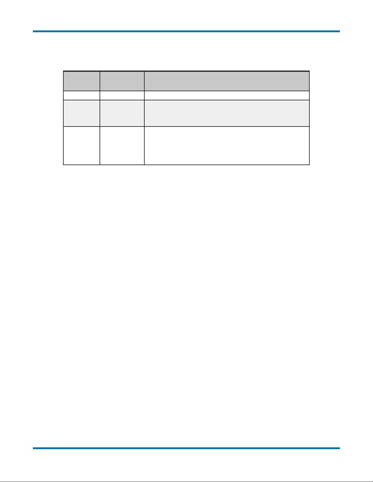
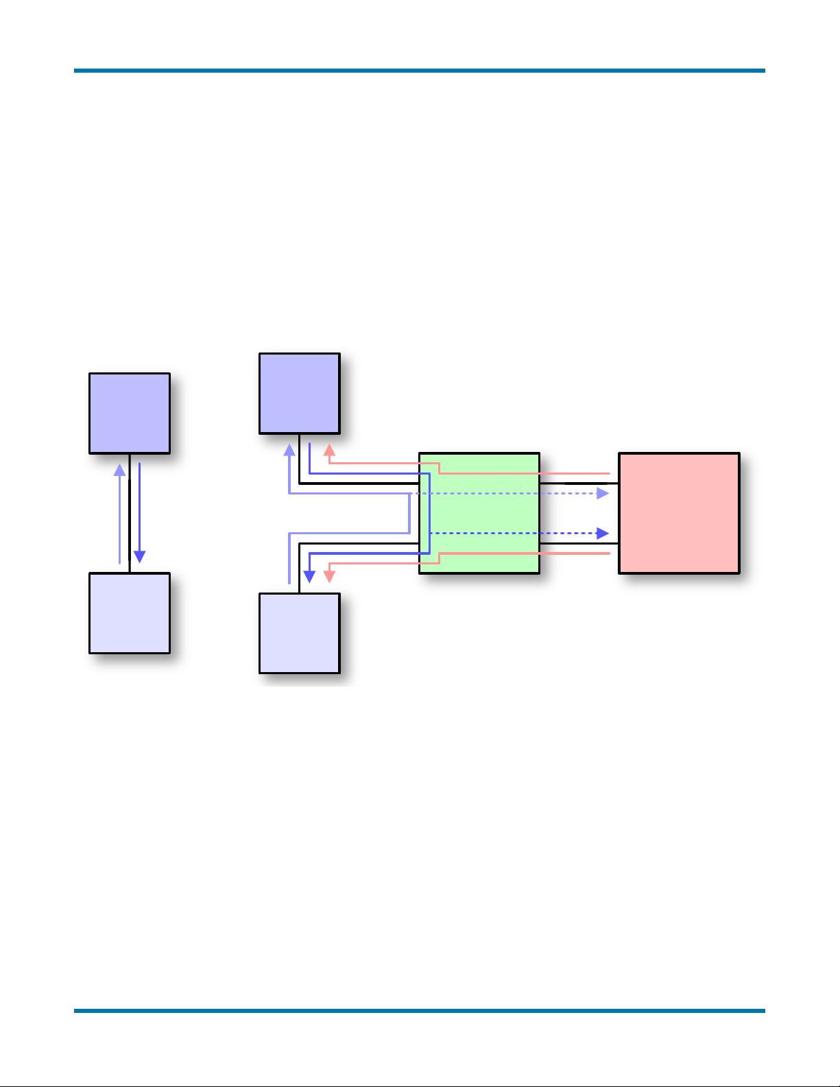
(such as attaching a probe to the bus) do not work. This problem is resolved by interposing the
RAD-Star between two Automotive Ethernet devices, typically an ECU and a switch. Instead
of connecting the ECU and switch directly, both are attached to the BroadR-Reach ports of the
RAD-Star. The 10/100 Ethernet links of the RAD-Star are then connected to a laptop PC or
similar conventional Ethernet device.
The RAD-Star is now set up as a “middle man” in the connection, managed by a custom-
designed XMOS active tap chip. When a message is sent by the ECU to the switch, the
RAD-Star receives it and immediately retransmits it over its other BroadR-Reach port so the

RAD-Star User’s Guide
2© 2015-2016 Intrepid Control Systems, Inc.Version 1.2 - June 1, 2016
message is received by the switch as usual, with only a minor delay for processing. The RAD-
Star also sends a copy of the message over conventional Ethernet to the PC so it can be
viewed and analyzed using a software tool such as Intrepid’s Vehicle Spy. A similar process
occurs for messages sent by the Automotive Ethernet switch: they are received by the RAD-
Star, forwarded to the ECU, and a copy also sent to the PC.
The interface provided by the RAD-Star is full-duplex and bidirectional. This means that
in addition to using the PC to monitor messages sent by the Automotive Ethernet devices
attached to it, you can create and send custom messages from the PC to the devices as well.
This allows you to query, test, congure and manage any BroadR-Reach ECU.
Figure 1 depicts how the RAD-Star functions when inserted into a network as an active tap.
AE
ECU
AE
Switch
ECU to
Switch
Switch
to ECU
AE
ECU
AE
Switch
Switch
to ECU
RAD-Star
Conventional
Ethernet
Network
ECU to
Switch
PC to
Switch
PC to
ECU
Figure 1: Using the RAD-Star as an Active Tap. On the left, a standard connection between an Automotive Ethernet switch
and a single ECU. (Other ECUs connected to the switch are not shown.) On the right, the network that results after inserting
the RAD-Star as an active tap. Messages ow from the switch through the RAD-Star to the ECU, and vice-versa, maintaining
normal operation of the network. In addition, copies of each message are transmitted by the RAD-Star to the attached
conventional Ethernet network. Optionally, messages from a PC or other device on the Ethernet network may also be sent to
the switch or ECU.
Operation as a Media Converter
If only one Automotive Ethernet device is connected to the RAD-Star, it will not forward
messages received from that device to its other BroadR-Reach port (since the second port
will not be connected). However, it will continue to send those messages to the attached
conventional Ethernet device, and conversely, will send messages from the conventional
Ethernet port to the AE ECU. In this conguration, the RAD-Star is said to be operating as a
media converter, because it converts messages from the Automotive Ethernet media format to
conventional Ethernet and vice-versa. This is depicted in Figure 2.

RAD-Star User’s Guide
3© 2015-2016 Intrepid Control Systems, Inc.Version 1.2 - June 1, 2016
AE
Device
Device
to PC
RAD-Star PC
PC to
Device
Figure 2: Using the RAD-Star as a Media Converter. Connecting just one Automotive Ethernet device to the RAD-Star
creates a simpler network that allows a PC or other standard Ethernet hardware to interact with it.
Timestamping and Frame Wrapping
The RAD-Star records the time that each message is received on one of its BroadR-Reach
ports. This hardware-level timestamp is then transmitted in a special wrapper frame over its
conventional Ethernet links, encapsulating the original message. The wrapper frame contains
its own Ethernet header and Frame Check Sequence (FCS) eld, along with an extra header
containing information specic to the RAD-Star. The wrapper is described further in Section 11.
Ethernet controllers normally discard any frames received for which an error has been
detected, and strip the FCS error-detection eld even on valid frames. The RAD-Star’s special
wrapping mechanism allows it to capture BroadR-Reach frames in their entirety, including
the FCS eld, and ensures that error frames are preserved so they can be analyzed. (Note,
however, that undersized/runt frames will not be captured.)
Features
Here are some of the noteworthy features of the RAD-Star:
• Custom XMOS BroadR-Reach active tap
• Support for active tap and media converter operation
• Two SMSC 8710A conventional 10/100 Ethernet PHYs
• Two BroadCom BCM89810 BroadR-Reach (100BASE-T1) PHYs
• Standard RJ-45 jacks for 10/100 Ethernet connections with link and activity LEDs
• Molex Mini50 jacks for Automotive Ethernet connections with combination link/activity
LEDs
• DC power input via standard DB-9 CAN connector
• Full-duplex support for simultaneous data transmission and reception across all PHYs
• Compact, portable enclosure
• Fast boot time: forwarding of BroadR-Reach packets on active tap within 120 ms,
transmission of tapped packets over standard Ethernet within 2.5 seconds.

RAD-Star User’s Guide
4© 2015-2016 Intrepid Control Systems, Inc.Version 1.2 - June 1, 2016
Block Diagram
Figure 3 illustrates the main functional elements of the RAD-Star.
XMOS
BroadR-Reach
Active TAP
Master
10/100
Ethernet
PHY
Master
BroadR
PHY
Slave
BroadR
PHY
Slave
10/100
Ethernet
PHY
Master
BroadR
Mini50
Connector
Slave
BroadR
Mini50
Connector
Master
Ethernet
RJ-45
Connector
Slave
Ethernet
RJ-45
Connector
Figure 3: RAD-Star Block Diagram.
4 Description of RAD-Star Interfaces and Indicators
We’ll now take a short tour of the RAD-Star, examining the external components of the device
and explaining what each does. The RAD-Star is designed so that all of its components are
located on its two sides, making the device easier to use in cramped quarters. We’ll identify
the sides by the type of Ethernet ports each contains, calling one the Automotive Ethernet Side
and the other the Conventional Ethernet Side.
Automotive Ethernet Side
This panel of the RAD-Star (Figure 4) contains a pair of Molex Mini50 jacks. While there is no
standardized Automotive Ethernet connector type, the Mini50 is used by many BroadR-Reach /
100BASE-T1 devices, including Broadcom switches and other Intrepid AE hardware.
BroadR-Reach requires that each link have one device serve as the master, while the other
acts as the slave. The two RAD-Star connectors are labeled to illustrate how they are internally
congured:
• BR MSTR: This port is set as a master device, and is intended to connect to an ECU or
switch port congured as a slave.
• BR SLAVE: This port acts as a slave device and should be linked to a master ECU or
switch port.

RAD-Star User’s Guide
5© 2015-2016 Intrepid Control Systems, Inc.Version 1.2 - June 1, 2016
Figure 4: RAD-Star Automotive Ethernet Side. The Mini50 BroadR-Reach connector on the left is internally congured as a
master device, while the one on the right is congured as slave. Each has a combination link/activity LED.
Note: One of the ways that BroadR-Reach delivers high per-
formance is by coordinating the operation of the two devices
on a link: the master device generates a clock signal, while the
slave device synchronizes its clock to that of the master. Aside from
this low-level timing functionality, there is no difference between the
master and the slave on a link. Note in particular that, despite the
names used, the master device does not control when or how the
slave device transmits; they operate independently.
Each port has a single LED that indicates the status of that port’s link as follows:
• LED Dark: No link has been established to the port.
• LED Continually Lit: Link established to another BroadR-Reach device.
• LED Flashing: Link is established and active; ashing rate indicates the level of trafc
activity for the port.
During normal operation as an active tap you will see both LEDs lit, and they will ash
intermittently or frequently depending on how active the link is. When using the RAD-Star as a
media converter, only the LED to which a BroadR-Reach cable is attached will illuminate.
Conventional Ethernet Side
Figure 5 shows the side of the RAD-Star intended to attach to a conventional Ethernet
network. The components seen here are the following:
• RJ-45 Ports: Two industry-standard conventional Ethernet jacks with indicator LEDs.
• CAN+PWR Port: A male DB-9 connector to provide power to the RAD-Star.

RAD-Star User’s Guide
6© 2015-2016 Intrepid Control Systems, Inc.Version 1.2 - June 1, 2016
Figure 5: RAD-Star Conventional Ethernet Side. The standard Ethernet RJ-45 jacks on this side of the RAD-Star
correspond to their equivalently-named jacks on the Automotive Ethernet side. Each has a link LED (above and left of the
port) and activity LED (above right). The CAN+PWR port provides power to the device using an industry-standard DB-9 CAN
connector.
There is no need to congure standard Ethernet ports as master or slave. The labels on the
jacks here are instead used to match up the conventional Ethernet ports with their Automotive
Ethernet equivalents, as follows:
• SLAVE: Carries copies of messages transmitted by the AE device connected to the
RAD-Star’s BR SLAVE port, as well as messages from an attached PC intended for that
device.
• MASTER: Carries messages coming from the device on the BR MSTR port, or going to
that device.
Each RJ-45 has a pair of integrated LEDs that provide information about it:
• Link LED (Above Left): Indicates that a valid link has been established between the
RAD-Star and the conventional Ethernet network.
• Activity LED (Above Right): Flashes when trafc passes in either direction over the
attached Ethernet cable.
When the RAD-Star is used as an active tap, both ports will have their link LEDs on, and their
activity LEDs will ash at a rate proportional to the amount of data being transferred. Using the
RAD-Star as a media converter will result in the LEDs being lit on the port with the attached
cable, while those on the other port will remain dark.
5 Hardware and Software Requirements
You will need a small amount of support hardware to effectively use the RAD-Star, with the
exact equipment requirements depending on the intended application. Note that cabling
requirements are described in more detail in the section following this one.

RAD-Star User’s Guide
7© 2015-2016 Intrepid Control Systems, Inc.Version 1.2 - June 1, 2016
Requirements to Use the RAD-Star as an Active Tap
To use the RAD-Star as an active tap you will need the following equipment:
• One Automotive Ethernet ECU and a free AE switch port, or two ECUs.
• A conventional Ethernet switch with at least two open ports, which should be Gigabit
Ethernet capable (see below).
• A PC with a free Ethernet port, preferably Gigabit Ethernet, capable of running analysis
software.
• An additional conventional Ethernet cable to connect the Ethernet switch and PC.
• A DB-9 / CAN power cable for the RAD-Star.
• Two BroadR-Reach cables with the correct termination for the Automotive Ethernet
devices being tested.
We recommend licensing Intrepid’s Vehicle Spy software for the analysis PC. Vehicle Spy is
a “Swiss army knife” of vehicle analysis and testing tools, and the RAD-Star was specically
designed to work with it. Please contact Intrepid Control Systems for more information on
Vehicle Spy.
Note that the conventional Ethernet switch is necessary for active tap operation because of
the RAD-Star’s two conventional Ethernet connections. If you are tapping links sending data at
high speed, the aggregate throughput of the two Ethernet links may exceed 100 Mb/s, and for
this reason we recommend that both the switch and PC Ethernet port support Gigabit Ethernet.
For lower-speed applications, slower 100 Mb/s (10/100) hardware may sufce.
You can also use an older Ethernet hub instead of the switch, but this is recommended only for
very-low-speed uses.
Requirements to Use the RAD-Star as a Media Converter
If you are using the RAD-Star as a media converter, the following changes apply to the list
above:
• Only one Automotive Ethernet device is needed, rather than two.
• Only one BroadR-Reach cable is required, with the correct termination for the ECU
being tested.
• No conventional Ethernet switch is necessary, nor an extra standard Ethernet cable.
• There is no need for a Gigabit Ethernet port (10/100 will sufce).

RAD-Star User’s Guide
8© 2015-2016 Intrepid Control Systems, Inc.Version 1.2 - June 1, 2016
6 Cables and Connectors
The cables and connectors used in automotive networks vary among applications and test
benches. Intrepid designed the RAD-Star to work with congurations that are commonly
available in the industry, but depending on your setup, it may be necessary to modify the
included cables or create new ones.
BroadR-Reach Cables
BroadR-Reach does not specify an industry-standard cable and connector type. However, the
Molex Mini50 is used by many BroadR-Reach devices, including Broadcom switches and other
Automotive Ethernet hardware made by Intrepid.
The RAD-Star ships with a pair of BroadR-Reach cables terminated in Mini50 plugs. One
end of each cable is intended to be attached to the RAD-Star, while the other end can be
connected to ECUs or switch ports that have Mini50 jacks.
If your AE hardware does not use Mini50, please snip off the Mini50 plugs on one end of each
of the supplied cables. Then simply attach the appropriate plug for the connector type used in
your application, or directly connect the bare wires to the devices you want to work with.
The pinout for the RAD-Star’s Mini50 jacks can be found in Table 1, with the pin numbers
illustrated in Figure 6. Note that this information is also printed on the bottom of the device.
Pin # Label Description
1 No Connect
2 TRD+ Data transmit and receive, positive
3 TRD- Data transmit and receive, negative
4 No Connect
Table 1: RAD-Star BroadR-Reach Mini50 Jack Pinout.
Figure 6: RAD-Star BroadR-Reach Mini50 Jack. Pins are numbered 1 to 4 from left to right looking at the jack, as shown.
Power Cable
The RAD-Star is powered through its DB-9 port (also called a DE-9), which is the standard
connector used in the automotive industry for the CAN bus. Most automotive test benches
should already have power supply cables using the matching DB-9 female connector. The

RAD-Star User’s Guide
9© 2015-2016 Intrepid Control Systems, Inc.Version 1.2 - June 1, 2016
RAD-Star operates at a nominal 12V and requires 300 mA of current at that voltage level, but
will accept equivalent power input at a range of 4.5V to 36V.
If your test bench does not have a suitable cable to power the RAD-Star, you can make
one from a female DB-9 connector and appropriate wiring; the pinout can be found in
Table 2, with pin numbers shown in Figure 7. Note that the LIN and CAN interfaces are for
internal use by Intrepid; the only end-user function of this cable is to supply DC power, so you
only need to connect pin 9 and one of the ground pins.
Pin # Label Description
1 LIN LIN interface (Intrepid use only)
2 HS CAN L High-speed CAN low (Intrepid use only)
3 GND Ground
4 No Connect
5 GND Ground
6 GND Ground
7 HS CAN H High-speed CAN high (Intrepid use only)
8 No Connect
9 V BATT DC voltage input
Table 2: RAD-Star CAN+PWR DB-9 Jack Pinout.
Figure 7: RAD-Star CAN+PWR DB-9 Jack. Pins are numbered 1 to 9 from left to right as shown.
7 Hardware Setup - Active Tap
In this section we explain the process of setting up the RAD-Star step by step. Note that
while the directions are listed in a particular order, the exact sequence in which the setup is
performed does not affect operation.
The instructions that follow assume that any necessary cables have already been fabricated or
modied as described in the previous section.
Figure 8 shows you at a glance how to set up the cables to use the RAD-Star as an active tap.

RAD-Star User’s Guide
10 © 2015-2016 Intrepid Control Systems, Inc.Version 1.2 - June 1, 2016
12V
ECU
Ethernet
Switch
Switch
or ECU
Figure 8: RAD-Star Active Tap Hookup Diagram.
Please follow these steps to complete the necessary connections:
1. Connect BroadR-Reach Cables to RAD-Star: Attach the Mini50 connectors on each
of the two BroadR-Reach cables to the BR MSTR and BR SLAVE jacks on the RAD-
Star (Figure 9). You should hear an audible click as each plug is seated.
Figure 9: Connecting BroadR-Reach Cables to the RAD-Star.
2. Connect BroadR-Reach Cables to ECU/Switch Ports: If you are testing a link
between an ECU and switch, attach the other ends of the BroadR-Reach cables to the
ECU and switch ports of that link. If testing a link between two ECUs, attach the cables
to those ECUs.
When connecting your Automotive Ethernet devices, attach the ECU or switch port congured
internally as a master to the BR SLAVE port of the RAD-Star, and the device congured as
slave to the BR MSTR port. Note that some AE devices can operate as master or slave and
can thus be connected to either port.

RAD-Star User’s Guide
11 © 2015-2016 Intrepid Control Systems, Inc.Version 1.2 - June 1, 2016
Note: If you are unsure which device on a link is the master
and which is the slave, just choose either device to connect to
BR SLAVE and the other to BR MSTR. If you guessed incorrectly,
the RAD-Star will not function, but you can simply swap the two
connectors—you can’t damage an ECU or the RAD-Star by
connecting two master or two slave devices to each other.
3. Connect Ethernet Cables to RAD-Star: Connect one end of each of the supplied
conventional Ethernet cables to the SLAVE and MASTER ports on the RAD-Star
(Figure 10). You will again hear a click as the jacks are attached.
Figure 10: Connecting Ethernet Cables to the RAD-Star.
4. Connect Ethernet Cable to PC: Connect a third Ethernet cable to the PC that you wish
to use to monitor trafc coming from the RAD-Star (Figure 11).
Figure 11: Connecting the Ethernet Cable to a PC.
5. Connect Ethernet Cables to Ethernet Switch: Insert the other ends of the cables you
just connected to the RAD-Star and PC into open jacks in your Ethernet switch (or hub).
(For most devices, the exact choice of ports on the switch/hub does not matter.)

RAD-Star User’s Guide
12 © 2015-2016 Intrepid Control Systems, Inc.Version 1.2 - June 1, 2016
Figure 12: Connecting Ethernet Cables to the Ethernet Switch.
6. Connect Power Supply to RAD-Star: Attach the cable coming from your DC power
supply to the RAD-Star as shown in Figure 13. Assuming that the power supply is
turned on, you should see the link LEDs light up for the RAD-Star’s two Ethernet
connections.
Figure 13: Connecting Power Cable to the RAD-Star.
Your RAD-Star is now ready to be used as an active tap; Figure 14 shows a complete sample
conguration. If you experience any issues setting up the hardware, please refer to the
enclosed troubleshooting and support information.

RAD-Star User’s Guide
13 © 2015-2016 Intrepid Control Systems, Inc.Version 1.2 - June 1, 2016
Figure 14: RAD-Star Congured for Active Tap Operation. We have used two Intrepid Ethernet Experimentation and
Evaluation Boards (EEVBs) as example ECUs here, for the purpose of illustration; these can be seen in the foreground,
attached to the RAD-Star. The component in the background on the left acts as a power supply.
8 Hardware Setup - Media Converter
Conguring the RAD-Star as a media converter involves the same basic process outlined in
the active tap description above, but the omission of the Ethernet switch makes this setup
considerably simpler. As before, you can make the connections in any order, and we assume
that you have already made or modied any necessary cables per the directions in Section 6.
The hookup diagram to use the RAD-Star as a media converter can be found in Figure 15.
The “ghosted” connections reect the fact that the ECU and PC can be connected to either the
MASTER / BR MSTR pair of ports, or the SLAVE / BR SLAVE pair.
12V
ECU
Figure 15: RAD-Star Media Converter Hookup Diagram.

RAD-Star User’s Guide
14 © 2015-2016 Intrepid Control Systems, Inc.Version 1.2 - June 1, 2016
Please complete these steps to use the RAD-Star as a media converter:
1. Connect BroadR-Reach Cable to RAD-Star: Attach the Mini50 connector on a
BroadR-Reach cable to the BR MSTR port if your ECU is congured as a slave device,
or BR SLAVE if it is congured as a master; Figure 16 shows an example of the former.
Note that some devices can operate as master or slave, so you can use either port. You
should hear a click when the plug snaps into place.
Figure 16: Connecting a BroadR-Reach Cable to the RAD-Star BR MSTR Port.
Note: If you are unsure of whether the ECU is a master or
slave, just choose either BR SLAVE or BR MSTR. If the RAD-
Star doesn’t work, you’ll know you chose incorrectly; the hardware
will not be damaged, and you can simply swap to the other port. If
you change which BroadR-Reach port you use, remember to also
change the Ethernet port you connect to as well.
2. Connect BroadR-Reach Cable to ECU: Attach the other end of the BroadR-Reach
cable to the ECU.
3. Connect Ethernet Cable to RAD-Star: If you used the BR MSTR port in Step 1,
connect one end of a standard Ethernet cable to the RAD-Star’s MASTER conventional
Ethernet port. If you used the BR SLAVE port in Step 1, instead connect it to the RAD-
Star’s SLAVE Ethernet port. Figure 17 shows the MASTER port being used.

RAD-Star User’s Guide
15 © 2015-2016 Intrepid Control Systems, Inc.Version 1.2 - June 1, 2016
Figure 17: Connecting an Ethernet Cable to the RAD-Star. The port chosen must match that chosen for the BroadR-Reach
cable. Here we are attaching to the MASTER Ethernet port because we used the BR MSTR port in Figure 16.
4. Connect Ethernet Cable to PC: Connect the other end of the Ethernet cable to the
Ethernet port on your PC (as shown earlier in Figure 11).
5. Connect Power Supply to RAD-Star: Attach the cable coming from your DC power
supply to the RAD-Star. If the power supply is on, the link LED for the connected
Ethernet port should now illuminate.
You’re done; the RAD-Star can now be used as a media converter (Figure 18 shows a typical
conguration). Please refer to the troubleshooting and support information that follows if you
encounter any problems with the setup.
Figure 18: RAD-Star Congured as a Media Converter. This setup uses the BR MSTR and MASTER ports as described in
the connection steps. We have again used an Intrepid Ethernet EVB as an example ECU.

RAD-Star User’s Guide
16 © 2015-2016 Intrepid Control Systems, Inc.Version 1.2 - June 1, 2016
9 Troubleshooting
All Intrepid products, including the RAD-Star, have been designed, manufactured and tested
to provide you with years of trouble-free service. However, as with any complex engineered
device, problems can occasionally arise, either with the product itself, or with the process of
setting up and using it.
If you’re experiencing difculties with your RAD-Star, please try some of the troubleshooting
ideas in this section. You may be able to save time by solving the problem yourself!
Note: These troubleshooting instructions are best attempted in
the order listed. In particular, make sure the appropriate link
LEDs are lit—indicating proper BroadR-Reach or Ethernet links are
established—before attempting to diagnose any data transmission
issues.
No LEDs Illuminated
This may happen if the RAD-Star has not been connected to any other devices. Check that at
least one of its Ethernet ports has been correctly connected to either type of Ethernet device
(BroadR-Reach or conventional) and that the device is powered on and operating.
If the RAD-Star is connected to a powered device and still has no LEDs lit, this usually means
that the RAD-Star itself is not receiving power. Try the following:
• Check the power connections on the RAD-Star and the power supply.
• Remove and then reconnect the power cable.
• Ensure that the power supply is turned on.
• Try connecting the power supply to a different device.
• Check the voltage setting on the power supply, if applicable.
• Try a different cable, if possible.
If the power supply and cable work with a different device but not the RAD-Star, this suggests
a possible hardware fault. Please contact Intrepid for further assistance.
Conventional Ethernet Link LED(s) not Illuminated
The RAD-Star has not established a link to the conventional Ethernet device(s) to which it has
been connected. Here are a few things that may help:
• Double-check the Ethernet connections on the RAD-Star and Ethernet device(s).

RAD-Star User’s Guide
17 © 2015-2016 Intrepid Control Systems, Inc.Version 1.2 - June 1, 2016
• Ensure that the Ethernet port on the device is enabled and active.
• Remove and reconnect the Ethernet cable.
• Try a different Ethernet port, if possible.
• Try a different Ethernet cable.
• If a switch or hub is being used, check that it is powered on and correctly congured.
• Disable and then enable the PC Ethernet port, or other conventional Ethernet device, to
which the Ethernet cable is attached.
In the unusual case that a supplied Ethernet cable is defective, Intrepid will replace it.
Automotive Ethernet Link LED(s) not Illuminated
The RAD-Star is not linked correctly to its attached BroadR-Reach device(s). Since BroadR-
Reach devices and cables vary, this issue may be application-dependent, but please try the
following:
• Ensure that a connection from the RAD-Star’s BR MSTR port goes to an ECU or
BroadR-Reach switch port congured as a slave device; similarly, any connection from
the BR SLAVE port should go to an ECU or switch port congured as a master. If you
are unsure, try switching the connections.
• Double-check the connections at both ends of the cable(s).
• Remove the cable from the RAD-Star and reconnect it.
• Check for a loose connection at the Automotive Ethernet device.
• Try a different cable, if possible.
Note: If you are using the RAD-Star as a media converter and
switch the BroadR-Reach connection from BR MSTR to BR
SLAVE, or vice-versa, be sure to make the corresponding change
to which RAD-Star conventional Ethernet port is attached (MASTER
to SLAVE or vice-versa).
Only One Automotive Ethernet Link LED Illuminated After Swapping Devices
Normally either both link LEDs will light up (correct master/slave conguration) or neither will
(incorrect conguration). If only one link LED illuminates, try swapping the devices again:
• If the illuminated link LED changes after swapping devices, the problem is with the
device connected to the RAD-Star BroadR-Reach port that is not illuminated.
Table of contents
Other Intrepid Control Systems Automobile Accessories manuals
Popular Automobile Accessories manuals by other brands

Champion Power Equipment
Champion Power Equipment 50028 Owner's Manual and Operating Instructions

Tellur
Tellur TLL151171 user manual

POOL-LINE
POOL-LINE 110016 Assembly instructions

Yakima
Yakima GetOut instructions

Trailboss
Trailboss QTMA662L Fitting instructions

Angel Armor
Angel Armor Avail installation guide