Libelium Waspmote Plug & Sense! Smart Parking Quick start guide

wasp
mote
Plug & Sense! Smart Parking
Technical Guide

-2-
v7.0
Document version: v7.0 - 10/2016
© Libelium Comunicaciones Distribuidas S.L.
INDEX
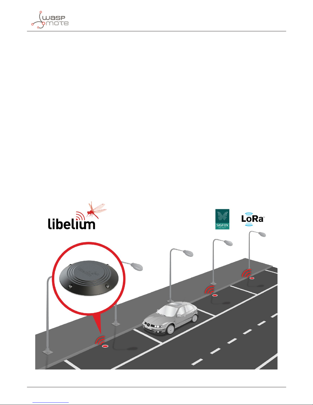
1. Introduction......................................................................................................................................... 4
2. General ................................................................................................................................................ 5
2.1. General and safety information..............................................................................................................................................5
2.2. Conditions of use .........................................................................................................................................................................5
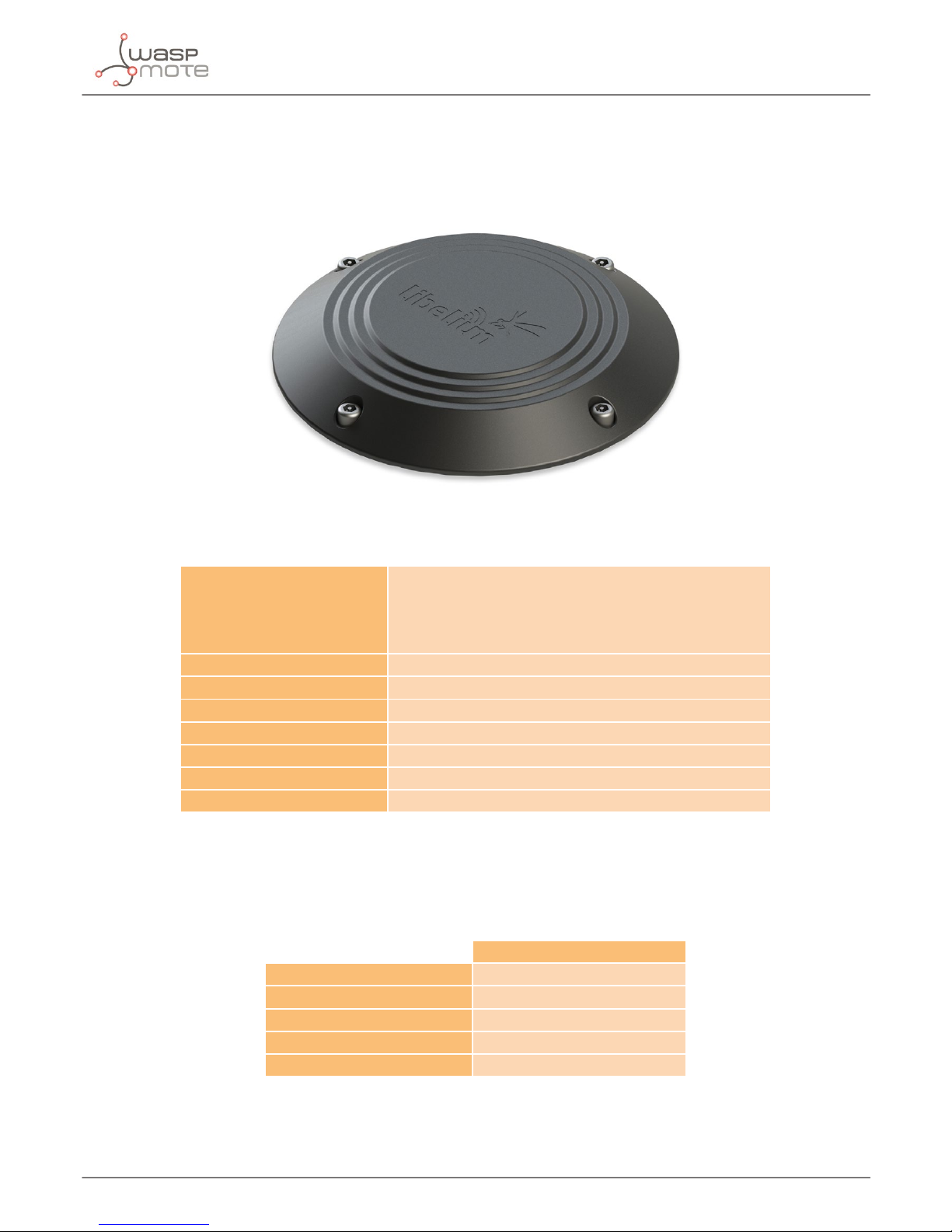
3. Hardware.............................................................................................................................................. 6
3.1. Hardware description.................................................................................................................................................................6
3.2. Power consumption....................................................................................................................................................................6
4. How the node works............................................................................................................................ 7
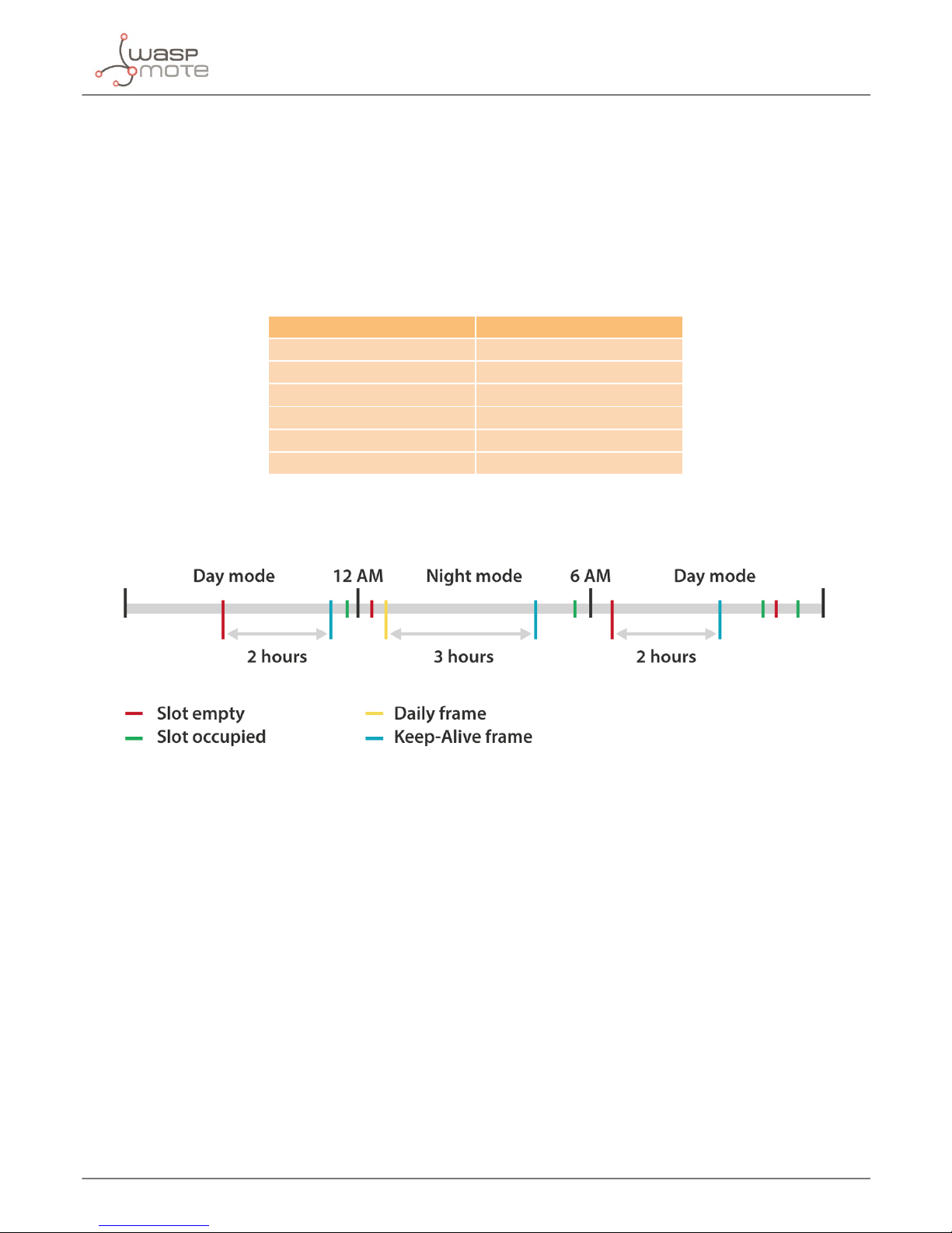
5. Sleep modes......................................................................................................................................... 8
5.1. Day mode........................................................................................................................................................................................8
5.2. Night mode ....................................................................................................................................................................................9
6. Transmission modes.......................................................................................................................... 10
7. Frames ................................................................................................................................................ 11
7.1. Info frame.....................................................................................................................................................................................12
7.2. Keep-Alive frame.......................................................................................................................................................................12
7.3. Daily update frame...................................................................................................................................................................13
7.4. Error frame...................................................................................................................................................................................14
7.5. Start frames................................................................................................................................................................................. 15
7.5.1. Start frame number 1 ...............................................................................................................................................15
7.5.2. Start frame number 2 ...............................................................................................................................................16
8. Smart Devices App ............................................................................................................................ 17
8.1. Installation................................................................................................................................................................................... 17
8.2. Smart Parking............................................................................................................................................................................. 17
8.2.1. Programmer .................................................................................................................................................................17
8.2.2. Firmware upgrade......................................................................................................................................................19
8.2.3. Conguration...............................................................................................................................................................21
9. Callback Server .................................................................................................................................. 22
9.1. Installation................................................................................................................................................................................... 22
9.2. Deploying ....................................................................................................................................................................................22
9.3. Making the server accessible from anywhere ................................................................................................................23
9.4. Remote node conguration web........................................................................................................................................23
Index

-3-
v7.0
10. Developing the network ................................................................................................................. 27
10.1. Application considerations.................................................................................................................................................27
10.1.1. Deployment of the motes ....................................................................................................................................27
10.1.2. Interference of other vehicles .............................................................................................................................28
11. Device Installation........................................................................................................................... 29
11.1. Assembly and set up ............................................................................................................................................................. 29
11.2. Installation and boot.............................................................................................................................................................31
11.3. Conguring the parking nodes in the callback server..............................................................................................33
12. Sigfox................................................................................................................................................ 34
12.1. Device conguration.............................................................................................................................................................34
12.2. Server conguration..............................................................................................................................................................38
13. Loriot ................................................................................................................................................ 39
13.1. Device conguration.............................................................................................................................................................39
13.2. Server conguration..............................................................................................................................................................40
13.3. Start the web-socket connection .....................................................................................................................................41
14. Actility .............................................................................................................................................. 42
14.1. Device conguration.............................................................................................................................................................42
14.2. Server conguration..............................................................................................................................................................45
15. Troubleshooting .............................................................................................................................. 46
15.1. Windows does not recognize USB ports .......................................................................................................................46
16. Certications.................................................................................................................................... 49
17. Disposal and recycling .................................................................................................................... 50
Index

-4-
v7.0
Introduction
1. Introduction
The new version of Waspmote Plug & Sense! Smart Parking, the solution for Smart Cities that allows citizens to detect
available parking spots.
The new device is easier and cheaper to deploy as it is mounted on the road surface. Unlike most market versions, it does not
need to dig a hole in the ground for installation, reducing installation time from 30 to 5 minutes and allowing to be replaced by
another unit in case of maintenance in just 10 minutes.
The smaller size -reduced over 50%-, its higher accuracy and reliability, and the faster time of detection, besides the independence
from temperature are also important features of new Smart Parking device.
New sensor system is fully compatible with LPWAN radio technologies -LoRaWAN and Sigfox- to enable long range and low
power consumption. It can be connected with both radios for the European 868 MHz band and for the 900-930 MHz band (US
/ Canada). One unique feature of the system is that it allows to use both radio technologies at the same time or changing from
one to the other using the manager system from the Cloud.
With the new sensor system, one base station can give service to thousands of devices around a range of several kilometers
in urban environment. This fact provides lower costs of installation since the number of base stations can be dramatically
reduced. Besides, the new sensor model has been optimized for really low-power operation, so the battery lifetime is extended
up to 10 years easily.
The new Smart Parking node has been granted with the CE / FCC / IC marks and provides a robust software which works
out-of-the-box. Developers do not have to cope with programming the nodes, they just have to specify the values of key
parameters in the rmware such as working cycle or night mode to be ready to work. Remote management and bidirectional
communication allows to change several parameters of the nodes from the Cloud. This means we can reprogram thousands of
nodes by just setting the right values from our web browser in the management platform.

-5-
v7.0
General
2. General
2.1. General and safety information
• In this section, the term “Waspmote” encompasses both the Waspmote device itself and it enclosure.
• Read through the document “General Conditions of Libelium Sale and Use”.
• Do not allow contact of metallic objects with the electronic part to avoid injuries and burns.
• NEVER submerge the device in any liquid with the enclosure open.
• Keep the device in a dry place and away from any liquid which may spill.
• Waspmote consists of highly sensitive electronics which is accessible to the exterior, handle with great care and avoid
bangs or hard brushing against surfaces.
• Check the product specications section for the maximum allowed power voltage and amperage range and consequently
always use a current transformer and a battery which works within that range. Libelium is only responsible for the correct
operation of the device with the batteries, power supplies and chargers which it supplies.
• Keep the device within the specied range of temperatures in the specications section.
• Do not connect or power the device with damaged cables or batteries.
• Place the device in a place only accessible to maintenance personnel (a restricted area).
• Keep children away from the device in all circumstances.
• If there is an electrical failure, disconnect the main switch immediately and disconnect that battery or any other power
supply that is being used.
• If a hardware failure occurs, consult the Libelium Web Development section.
• Check that the frequency and power of the communication radio modules together with the integrated antennas are
allowed in the area where you want to use the device.
2.2. Conditions of use
• Read the “General and Safety Information” section carefully and keep the manual for future consultation.
• Use Waspmote in accordance with the electrical specications and the environment described in the “Hardware”section of
this manual.
• Do not place Waspmote in contact with metallic surfaces; they could cause short-circuits which will permanently damage it.
• IMPORTANT It is the responsibility of the installer to nd out about restrictions of use for frequency bands in each country
and act in accordance with the given regulations. Libelium Comunicaciones Distribuidas S.L does not list the entire set of
standards that must be met for each country.
• For further information go to:
- CEPT ERC 70-03E - Technical Requirements, European restrictions and general requirements: http://www.erodocdb.dk/
- R&TTE Directive - Equipment requirements, placement on market: http://www.erodocdb.dk/
• Further information you may need can be found at: http://www.libelium.com/development/waspmote
• The “General Conditions of Libelium Sale and Use” document can be found at:
http://www.libelium.com/development/waspmote/technical_service

-6-
v7.0
Hardware
3. Hardware
3.1. Hardware description
Figure : Plug & Sense! Smart Parking
Operating frequency
Sigfox radio for Europe: 868.0 to 869.7 MHz
LoRaWAN radio for Europe: 863.0 to 870.0 MHz
Sigfox radio for USA: 902.0 to 928.0 MHz
LoRaWAN radio for USA: 902.0 to 928.0 MHz
Power supply Built-in Lithium batteries, expected lifetime of 4-6 years *
Antenna Included
Detection Magnetic
Mounting Over the oor
Dimensions 230 mm diameter, 28 mm height
Protection IP67, completely sealed housing
Operating temperature -20 to +65 °C
* Under normal circumstances and dependent on settings
Figure : Plug & Sense! Smart Parking main characteristics
3.2. Power consumption
Consumption
Measuring sensor TBD
Transmission Sigfox TBD
Transmission LoRaWAN TBD
Sleep state 25 µA
Battery self discharge < 1% month at +20 ºC
Figure : Plug & Sense! Smart Parking power consumption

-7-
v7.0
How the node works
4. How the node works
Figure : Basic working loop diagram
As the diagram indicate, the basic loop of the node consists in read the sensor and send a frame when the parking slot change
it status. Then, it sleeps a desired time and starts the loop again.
Some events can forced the node to send a frame to the cloud. If a desired time elapsed since the last radio transmission, the
node will send a Keep-Alive frame. This frame only contains basic data from the node (parking slot status and battery status). It
is useful to know that there is no changes in the slot, but the node still working. The node also will send a frame each 24 hours
with the working data of the day (number of measurements, number of transmissions,…).
Figure : Extended loop diagram

-8-
v7.0
Sleep modes
5. Sleep modes
Plug & Sense! Smart Parking has 2 sleep modes: day mode and night mode. The second one has been developed to use when
the parking slot is expected to have fewer changes (i.e. at night). Each mode has its own conguration parameters. The gure
below shows an example for the node transmissions in a day. The time zone between 6 AM and 12 AM (in light gray) indicates
that the node are working in day mode. In this mode, the sampling of the parking slot is made more regular (1 minute) and the
Keep-Alive is only 2 hours. In the dark gray zone, from 12 AM to 6 AM, the node is working in night mode. As is shown in the
example, the sampling time is greater (10 minutes) and the Keep-Alive increases too (3 hours).
Example conguration:
Parameter Conguration
Sleep time 1 minute
Keep-Alive 2 hours
Night Mode start hour 00 hours
Night Mode duration 6 hours
Night Mode Sleep Time 10 minutes
Night Mode Keep-Alive 3 hours
Figure : Example conguration
Figure : Day and night modes example
5.1. Day mode
It is the basic working mode and it has 2 congurable parameters:
• Sleep time: Sleep time between consecutive sensor measurements. 2 minutes option is congured by default.
• Keep-Alive: Elapsed time since last transmission to trigger a Keep-Alive frame. 10 hours option is congured by default.
This frame only contains basic data from the node (parking slot status and battery status). It is useful to know that there
are no changes in the slot, but the node still working. This mode can be disabled using both the USB Programmer or the
Remote Manager.

-9-
v7.0
Sleep modes
5.2. Night mode
This mode has been developed to use when the parking slot is expected to have fewer changes (i.e. at night) and it has 4
congurable parameters:
• Night Mode start hour: Beginning hour of the night mode. 22 hours option is congured by default.
• Night Mode duration: Night mode duration time. 8 hour option is congured by default.
• Night Mode Sleep Time: Sleep time between consecutive sensor measurements (during night mode). 10 minutes option
is congured by default.
• Night Mode Keep-Alive: Elapsed time since last transmission to trigger a Keep-Alive frame (during night mode). 4 hours
option is congured by default. This frame only contains basic data from the node (parking slot status and battery status).
It is useful to know that there is no change in the slot, but the node is still working.
This mode can be disabled using both the USB Programmer or the Remote Manager.

-10-
v7.0
Transmission modes
6. Transmission modes
Plug & Sense! Smart Parking has 5 transmission modes allowing to the user to choose between Sigfox, LoRaWAN y their
combinations:
• Sigfox. This mode only use the Sigfox radio to send the data collected by the node. This mode is selected by default.
• LoRaWAN. This mode only use the LoRaWAN radio to send the data collected by the node
• Sigfox + LoRaWAN. In this mode the data collected is sent using the 2 radios. It is recommended to test the node with the
two transmission technologies.
• Sigfox →LoRaWAN. This mode uses Sigfox radio as primary radio. If there is an issue with the Sigfox radio, it will use
LoRaWAN to send the frames.
• LoRaWAN →Sigfox. This mode uses LoRaWAN radio as primary radio. If there is an issue with the LoRaWAN radio, it will
use Sigfox to send the frames.

-11-
v7.0
Frames
7. Frames
Plug & Sense! Smart Parking node can send 6 dened frames. All frames are 12 bytes length and they are the same for Sigfox and
LoRaWAN. Bytes 0 and 1 are common for all frames. Byte 0 has the basic data from the node and frame and byte 1 its a frame
counter. It can be used to detect lost frames.
Bit Name Description
7 Parking slot status '0' indicates that the parking slot is empty
'1' indicates that the slot is in occupied
6 Battery state
'0' indicates that the battery has a good level of charge
'1' indicates that the battery has little charge and it will be necessary to
change it. When the battery has little charge it is possible that the node does
not work properly and the radios fail sending the frames.
5-4 Reserved Reserved bits. Do not consider.
3
Frame type
0 – Info frame
1 – Keep-Alive frame
2 – Daily update frame
3 – Error frame
4 – Start frame 1
5 – Start frame 2
Values from 6 to 15 are reserved
2
1
0
Figure : Byte 0 description

-12-
v7.0
Frames
7.1. Info frame
It is the most common frame sent by the node. The node will send this kind of frame each time it detects that the parking slot
changed from empty to occupied or vice-versa. The other bytes are used to give additional data to the user.
Byte Name Description
0 Basic data Detailed description in the section “Frame”
1 Frame counter Detailed description in the section “Frame”
2 Temperature MSB
Raw temperature from the node’s internal sensor. The value stored
in these two bytes is a 16-bit value in 2’s complement form. To
convert to Celsius degrees use the next formula:
3 Temperature LSB
4 X axis measurement MSB Raw value from the sensor associated to the X axis. The value stored
in these two bytes is a 16-bit value in 2’s complement form.
5 X axis measurement LSB
6 Y axis measurement MSB Raw value from the sensor associated to theY axis. The value stored
in these two bytes is a 16-bit value in 2’s complement form.
7 Y axis measurement LSB
8 Z axis measurement MSB Raw value from the sensor associated to the Z axis. The value stored
in these two bytes is a 16-bit value in 2’s complement form.
9 Z axis measurement LSB
10-11 Reserved Reserved bytes. Do not consider.
Figure : Info frame structure
7.2. Keep-Alive frame
This frame is used to indicate that the parking slot has not changed, but the node is still working.
Byte Name Description
0 Basic data Detailed description in section “Frame”
1 Frame counter Detailed description in section “Frame”
2 Timestamp (hh) Current hours
3 Timestamp (mm) Current minutes
4 Temperature MSB
Raw temperature from the node's internal sensor. The value stored in
these two bytes is a 16-bit value in 2’s complement form. To convert to
Celsius degrees use the next formula:
5 Temperature LSB
6 X axis measurement MSB Raw value from the sensor associated to the X axis. The value stored in
these two bytes is a 16-bit value in 2’s complement form.
7 X axis measurement LSB
8 Y axis measurement MSB Raw value from the sensor associated to the Y axis. The value stored in
these two bytes is a 16-bit value in 2’s complement form.
9 Y axis measurement LSB
10 Z axis measurement MSB Raw value from the sensor associated to the Z axis. The value stored in
these two bytes is a 16-bit value in 2’s complement form.
11 Z axis measurement LSB
Figure : Keep-Alive frame structure

-13-
v7.0
Frames
7.3. Daily update frame
This frame is sent daily at 1 AM. It contains a little summary. This frame can be deactivated using the Plug & Sense! Smart Parking
USB Programmer or via radio, with the response given by the Remote Manager, hosted in the cloud.
Byte Name Description
0 Basic data Detailed description in section “Frame”
1 Frame counter Detailed description in section “Frame”
2 Sensor measurements MSB Unsigned 16 bit counter. It stores the times that the sensor is used in
the last 24 hours.
3 Sensor measurements LSB
4 Sigfox transmissions MSB Unsigned 16 bit counter. It stores the times that Sigfox radio is used in
the last 24 hours.
5 Sigfox transmissions LSB
6 LoRaWAN transmissions MSB Unsigned 16 bit counter. It stores the times that LoRaWAN radio is
used in the last 24 hours.
7 LoRaWAN transmissions LSB
8 Resets Number of resets generated in the last 24 hours
9 Cong_id Value of the conguration version loaded into the node
10-11 Reserved Reserved bytes. Do not consider.
Figure : Daily update frame structure
This frame is sent daily at 1 AM. It contains a little summary. This frame can be deactivated using the Plug & Sense! Smart Parking
USB Programmer or via radio, with the Remote Manager, setting to 0 the enable/disable daily frame bit.
The daily update frame is very special because the node waits for a response after it is sent.This response is useful for reconguring
the node “over the air”, without physical access. Also, a second use of this response frame is to synchronize the node’s internal
clock, thanks to a timestamp. This response can be congurated using the remote PHP.

-14-
v7.0
Frames
7.4. Error frame
In some cases the node could send a frame if some internal components or processes fail.
Byte Name Description
0 Basic data Detailed description in section “Frame”
1 Frame counter Detailed description in section “Frame”
2 Error data Detailed description below
3 Temperature MSB
Raw temperature from the node’s internal sensor. The value stored in
these two bytes is a 16-bit value in 2’s complement form. To convert to
Celsius degrees use the next formula:
4 Temperature LSB
5 X axis measurement MSB Raw value from the sensor associated to the X axis. The value stored in
these two bytes is a 16-bit value in 2’s complement form.
6 X axis measurement LSB
7 Y axis measurement MSB Raw value from the sensor associated to the Y axis. The value stored in
these two bytes is a 16-bit value in 2’s complement form.
8 Y axis measurement LSB
9 Z axis measurement MSB Raw value from the sensor associated to the Z axis. The value stored in
these two bytes is a 16-bit value in 2’s complement form.
10 Z axis measurement LSB
11 Battery level
Battery voltage in millivolts. To convert to millivolts use the next
formula:
Figure : Error frame structure

-15-
v7.0
Frames
Bit Name Description
7-6 Reserved Reserved bits. Do not consider.
5 Error Sigfox Set to '1' when an error related with the Sigfox radio is detected. Clear
when no issues detected.
4 Error LoRaWAN Set to '1' when an error related with the LoRaWAN radio is detected.
Clear when no issues detected.
3 Error RTC Set to‘1’when an error related with the RTC (internal clock) is detected.
Clear when no issues detected.
2 Error X axis Set to '1' when an error appears in the X axis of the sensor. Clear when
no issues detected.
1Error Y axis Set to '1' when an error appears in the Y axis of the sensor. Clear when
no issues detected.
0 Error Z axis Set to '1' when an error appears in the Z axis of the sensor. Clear when
no issues detected.
Figure : “Error data” byte structure
7.5. Start frames
When the node starts to work in the parking slot, it will send 2 frames. The rst one is dedicated to the sensor and the battery.
The second one is used to send some parameters about the chosen conguration.
7.5.1. Start frame number 1
Byte Name Description
0 Basic data Detailed description in section “Frame”
1 Frame counter Detailed description in section “Frame”
2 Temperature MSB
Raw temperature from the parking internal sensor. The value stored in
these two bytes is a 16-bit value in 2’s complement form. To convert to
Celsius degrees use the next formula:
3 Temperature LSB
4 X axis reference MSB Reference value from the sensor associated to the X axis. The value
stored in these two bytes is a 16-bit value in 2’s complement form.
5 X axis reference LSB
6 Y axis reference MSB Reference value from the sensor associated to the Y axis. The value
stored in these two bytes is a 16-bit value in 2’s complement form.
7 Y axis reference LSB
8 Z axis reference MSB Reference value from the sensor associated to the Z axis. The value
stored in these two bytes is a 16-bit value in 2’s complement form.
9 Z axis reference LSB
10 Battery voltage MSB Battery voltage in millivolts. The value stored in these two bytes is an
unsigned 16-bit value.
11 Battery voltage LSB
Figure : Start frame number 1 structure

-16-
v7.0
Frames
7.5.2. Start frame number 2
Byte Name Description
0 Basic data Detailed description in section “Frame”
1 Frame counter Detailed description in section “Frame”
2 CODE_ID Firmware version
3 NM_START Beginning hour of the night mode
4 NM_PERIOD Duration in hours of the night mode
5 NM_SLEEP_TIME Sleep time between consecutive sensor measurements (during night
mode)
6 NM_KEEP_ALIVE Elapsed time since last transmission to trigger a Keep-Alive frame
(during night mode)
7 RADIO_MODE Selected transmission mode between Sigfox, LoRaWAN y their
combinations
8 SLEEP_TIME Sleep time between consecutive sensor measurements
9 KEEP_ALIVE Elapsed time since last transmission to trigger a Keep-Alive frame
10 THRESHOLD Threshold for detecting a vehicle over the parking slot
11 Reserved Reserved byte. Do not consider.
Figure : Start frame number 2 structure

-17-
v7.0
Smart Devices App
8. Smart Devices App
Libelium Smart Devices App is an important tool developed by Libelium that allows users install new rmware versions and
program the conguration of the new Libelium devices in a few clicks. At the moment it is only available for SmartParking and
MySignals products, but the list will be incremented shortly.
8.1. Installation
First of all and before installing anything, users have to take into account the platform where the application is going to be
installed. To install the Libelium Smart Devices App, it is compulsory to have installed the JDK 1.8. If it is not installed in the
computer, you can follow the steps and download it from this website:
https://docs.oracle.com/javase/8/docs/technotes/guides/install/install_overview.html
Once installed JDK, users can download the application using the appropriate link depending on the operative system:
• Ubuntu: http://downloads.libelium.com/smart_device_app/SmartDeviceApp_linux64.zip
• Windows: http://downloads.libelium.com/smart_device_app/SmartDeviceApp_windows32.zip
• Mac: http://downloads.libelium.com/smart_device_app/SmartDeviceApp_macosx64.zip
Then customers only have to extract the content of the SmartDeviceApp zip le downloaded in a place with the right permissions,
and nally execute the le called“SmartDeviceApp” that will initialize the application. Please, note that the extension of this le
will depend on the operative system the user is using at the moment (sh for Linux and OSX, and bat for Windows).
8.2. Smart Parking
This section provides several options to Smart Parking users in order to take full advantage of all possibilities the devices oers.
8.2.1. Programmer
Figure : Smart Parking conguration form

-18-
v7.0
Smart Devices App
Users can read and write all conguration parameters of their devices in this section. The process is quite simple. Just connect
the device to the computer where the Smart Devices App is installed using the USB cable provided.
Figure : USB settings
Then, refresh the “USB settings” block which is in the bottom-right corner, clicking in “refresh” button. Once done it, the port
where the device has been connected must be selected.
But before conguring the device, it is very important that users take in consideration the following list where all parameters
are explained:
TIME SETTINGS
•Sleep time: Sleep time between consecutive sensor measurements.
•Keep-Alive: Elapsed time since last transmission to send a Keep-Alive frame.
NIGHT MODE
•On/O button: Button to activate/deactivate this option. If it is not active, the following elds will not be eective.
•Duration: Night mode duration time.
•Start hour: Night Mode start hour.
•Sleep time: Sleep time between consecutive sensor measurements (during night mode).
•Keep-Alive: Elapsed time since last transmission to send a Keep-Alive frame (during night mode).
EXTRA CONFIGURATION
•Sensor Threshold: Threshold for detecting a vehicle over the parking slot.
•Battery readings per day: Battery readings per day.
•Daily frame: Enable/Disable daily frame sending.
RADIO MODE
•Radio mode: Radio transmission mode among Sigfox, LoRaWAN or their combinations.
LoRaWAN parameters
•LoRaWAN join mode: LoRaWAN join mode, ABP or OTAA.
•Device EUI: LoRaWAN device EUI.
•Device Address: LoRaWAN device address.
•Port: LoRaWAN port.
•Network Session Key: LoRaWAN network session key.
•Application Session Key: LoRaWAN application session key.
•Application Key: LoRaWAN application key.
•Application EUI: LoRaWAN application EUI.

-19-
v7.0
Smart Devices App
Sigfox ID: Sigfox ID that will be loaded from the device.
• LoRaWAN EUI: LoRaWAN EUI that will be loaded from the device.
USB SETTINGS
• USB Port: In this list will be displayed all available USB ports to work out with the device. If you plug your device and the
port is not listed, you have click on“Refresh”button in order to update the list.
Figure : Load conguration from node & Send conguration to node buttons
“Load from node” button will read all parameters from the node and will displayed the information in the form. On the other
hand “Send to node” button will overwrite the conguration in the node. All available elds have to be lled, with the proper
format. If any parameter doesn’t have an acceptable format, a red cross like this IMAGEN app_cross.png will be displayed near
it and you can’t write the information in the node. If the information introduced is valid, a green tick IMAGEN app_tick.png will
be shown.
8.2.2. Firmware upgrade
In this tab, users can select the rmware version to install in their devices.
Figure : Smart Parking rmware upgrade form

-20-
v7.0
Smart Devices App
The list with all available rmware is loaded when the program starts, but users can update it on demand, clicking on “Search
new rmware updates” button. Before installing the rmware, it is necessary to download it. This process is very simple, just
mark the check of the version you want to install from the list IMAGEN app_check.png and click on“Download checked”button.
Figure : Download the rmware selected
When this item is downloaded, a disk will be displayed near it IMAGEN app_disk.png, indicating it is downloaded. Once the
rmware is downloaded, it is ready to install using the“Install Firmware” section at the bottom. In the drop-down will appear all
downloaded versions. Select one and then hit on “Install” button.
Figure : Install the rmware selected
You can also delete the downloaded rmware marking the check from the list IMAGEN app_check.png and then clicking on
“Delete checked” button.
Figure : Delete downloaded rmware
Remember that the USB port must be selected in the programmer tab.
Table of contents
Popular Automobile Accessories manuals by other brands

Freedom Motors
Freedom Motors REAR-ENTRY CONVERSION manual

Metec
Metec 840405 Mounting instructions

Thule
Thule 157 Mounting & installation

AA Products
AA Products APX2503 instruction manual

Twinny Load
Twinny Load A 26 Fitting instructions

Over Armour Offroad
Over Armour Offroad KU-X900-FC04 Instructions for Installation and Care